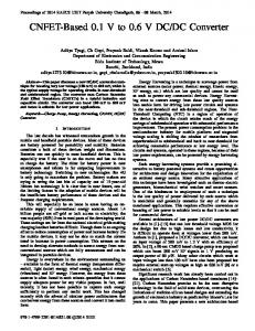
New Control Methods for Matrix Converter based UPFC Under Unbalanced Load Farzad Mohammadzadeh Shahir, Ebrahim Babaei, Member IEEE, Samira Ranjbar, Saman Torabzad Faculty of Electrical and Computer Engineering University of Tabriz Tabriz, Iran
[email protected],
[email protected],
[email protected],
[email protected]
Abstract—Recent development of power electronics introduces the use of flexible ac transmission systems (FACTS) controllers in power systems. These devices are helping to performance of power system especially when power system supports unbalanced loads. One of the most important of FACTS devices is unified power flow controller based on matrix converter (UPFC-MC) which space vector modulation (SVM) technique is used to control its nine-bidirectional switches. This paper presents two control methods for UPFC-MC under unbalanced power system. These control methods are suggested to improve transmission lines power flows. The validity of the proposed control methods are reconfirmed by simulation results. Keywords-FACTS; UPFC; matrix converter; unbalanced loads; compensation; optimum control
NOMENCLATURE
Index i Index o mb b = i, o δ b b = i, o ωb b = i, o φb b = i, o Ii Vo I i , k k = a , b, c
Index to show input side quantities Index to show output side quantities Modulation index of b side Phase angle of b side Switching angular frequency of b side Phase difference of b side Peak value of input current Peak value of output voltage Input current of phase k in b side
Vo , k k = a, b, c
Output voltage of phase k in b side
I i*
Reference of input current vector
Vo*
Reference of output voltage vector
TS Tκ , Tγ , Tα , Tβ
Switching time in a period
dκ , dγ , dα , d β
Duty cycles in adjacent vectors
Iκ , I γ
Adjacent vectors of input current
Vα ,Vβ
Adjacent vectors of output voltage
Switching times in adjacent vectors
I i ,0
Input current in zero time
Vo ,0
Output voltage in zero time
978-1-4673-0934-9/$31.00 ©2012IEEE
d b,0 b = i, o
Zero duty cycle in b side
Tb,0 b = i, o
Zero switching time in b side
I. INTRODUCTION FACTS controllers are introduced to the power system to enhance the security, capacity, and flexibility of power transmission systems. FACTS devices can reduce the power flows of heavily loaded lines, maintain the bus voltages at desired levels, and improve the stability of the power network [1-2]. Consequently, they can improve the power system security under contingency situations. UPFC is a versatile FACTS device which can independently or simultaneously control the active power, reactive power, and the bus voltage to which was introduced by Gyugyi in 1991 [3]. One of the best-presented structures for UPFC is based on matrix converter [4-5]. The matrix converter structure is based on nine-bidirectional switches which can be switched in high frequencies and directly transmit the energy in ac/ac mode applying no electrolyte capacitor. The matrix converter structure has the advantageous such as adjustable power factor, high qualitative input and output currents, high operation speed, and lower size, in addition to possessing no electrolyte capacitor in dc link. It also possesses disadvantageous such as restricted voltage transfer ratio by 0.86 and requiring numerous high power semiconductor devices capable of high frequency switching. According to the considerable advantageous of matrix converter structure, in compare with its disadvantageous, it quickly supersedes ac/dc/ac converters in scientific researches. The structure of UPFC-MC has been presented in [6] and its control strategy for balanced load has been presented in [7]. The dynamic model and stability evaluation of UPFC-MC has been described in [8-9] to optimum control in power system and attenuate rotor oscillations of synchronous generator. In this paper, two new strategies are introduced for switching and controlling the UPFC-MC under unbalanced loads condition. In order to evaluate the proposed control strategies to improve the distribution of active and reactive power flows in unbalanced power system, UPFC-MC is installed on a unbalanced power system. Finally, impacts of
proposed strategies are presented to improve power flows, separately.
II.
STRUCTURE OF UPFC-MC
A. Topology of UPFC-MC The structure of UPFC-MC is shown in Fig. 1 that includes nine-bidirectional switches, Y-Y and ∆ − ∆ transformers, and, input and output filters. These bidirectional switches are used to directly connect each one of the three phases to three output phases. Also, passive filters are applied to eliminate the high frequency component from input currents and output voltages.
The UPFC-MC input current relations in shunt side and fundamental component of voltage injected into transmission line in the series side is described as follows, respectively [1011]: I i , a = I i cos(ωi t − φi )
B. Modulation technique The most distinctive restriction of utilizing UPFC-MC falls in its switching pattern, which just holds 27 permitted modes out of 29 = 512 possible modes. This refers to the nature of matrix converter structure, which is due to impossibility of short circuiting input phases and impossibility of open circuiting output phases during each switching period. Two well-known control methos Venturini [12] and SVM [13], were presented to control 27 permitted switching modes of UPFCMC. The SVM algorithm is based on three-phase input current of line and three-phase output voltage. Figs. 2(a) and 2(b) show the input current space vector hexagon and output voltage space vector hexagon, respectively.
In each of the six sections of Fig. 2(a), two adjacent vectors, I κ and I γ , and the zero vector, I i , 0 are for production of reference input current vector. The reference input current vector is described as follows [13]:
I i* =
I i ,b = I i cos(ωi t − φi − 120° )
(1)
Tγ T Tκ Iκ + I γ + i ,0 I i ,0 = dκ Iκ + dγ Iγ + di ,0 I i ,0 TS TS TS
(3)
°
I i ,c = I i cos(ωi t − φi − 240 )
In (3), d κ , d γ , and d i ,0 are as follows, respectively [13]: V o ,a = V o cos(ωo t − φo ) V o ,b = V o cos(ωo t − φo − 120° )
(2)
V o ,c = V o cos(ωo t − φo − 240° )
d κ = m i sin(60° − δ i )
(4)
d γ = m i sin(δ i )
(5)
d i ,0 = 1 − d κ − d γ I o, a
Vo,a
Io ,b
So, the duty cycle and input current modulation index of input are described as follows, respectively [13]:
Vo,b
Vo,c
I o ,c
output filter
di ,1 = dκ + dγ = mi sin(60° − δ i ) + mi sin(δ i )
(7)
Va Vb
Vc
mi = input filter
(6)
Ia
Ib
Ic
ii 3 i DC
(8)
Fig. 2(b) shows SVM hexagon for inverter operation. The reference of output voltage vector can be approximated by two adjacent switching state vectors, V α and V β , and the zero voltage vector, V o , 0 using PWM technique as follows [13]: matrix converter
Vo* = Fig. 1.
Tβ T Tα Vα + Vβ + o ,0 Vo ,0 = dα Vα + d β Vβ + d o ,0Vo ,0 (9) TS TS TS
Topology of UPFC-MC
In (9), dα , d β , and d o ,0 are as follows, respectively [13]:
d α = m o sin(60° − δ o )
(10)
d β = m o sin(δo )
(11)
active and reactive powers are compared with reference value in every moment. Finally, in order to transfer maximum power, the control parameter can be set. Then, through UPFCMC, by increasing the lowest power factor, the capacity of transmission line increase. Vinj ,a ,b ,c
d o ,0 = 1 − d α − d β
I inj ,a ,b ,c
VL ,a ,b ,c
(12)
instantaneous active and reactive power
PLL
Thus, the duty cycle and modulation index of output voltage are described as follows [13]:
on each 3 − phase
θL
ωt I L ,a ,b ,c
d o ,1 = dα + d β = mo sin(60° − δ o ) + mo sin(δ o )
(13)
abc − to − dqo
vd vq
calculating average
abc − to − dqo
iq
of active and
id
reactive power calculating
mo =
vo 3 v DC
(14) +
Im I 2
V o ,b
II
III I3
I1
I4
I6 VI
I i ,c
I5
(a) Fig. 2.
I i ,0
I Re I i ,a
IV
V
Im V
+
2
II
III V3
V1
V o ,0
I Re V out ,a
IV V4
Pref ×
PI 1 PI 2 ωL ωL vd* v* − q − + + vd ,av vq ,av
cos
×
sin
PI 3 PI 4 mi θi
V6
V
VI
V o ,c
SVM hexagon
V5
(a)
(b)
Vinj ,a ,b ,c
At second control scheme that is proposed on minimum power factor correction as shown in Fig. 3(b), the power factors on each three phase are calculated in every moment from injected voltages and currents. The lowest phase power factor is selected from load and injected quantities and its phase angle is determined ( θ PF ). The injected phase angle is determined from θ L (phase angle of PLL ), θ dif , and θ PF . According to obtained phase difference, θ , the reference values of active and reactive powers can be calculated. The
I inj ,a ,b ,c
V L , a ,b , c
PROPOSED CONTROL METHODS
Two proposed control schemes are shown in Fig. 3. These control methods are based on average maximum transfer power and minimum power factor correction. The main purpose of these control methods are more power transfer. At first control method that is based on average maximum transfer power as shown in Fig. 3(a), instantaneous active and reactive powers on each three phase were calculated from injected voltages and currents. Due to different active and reactive powers in three-phase lines, the average active and reactive powers are determined. Then, the obtained average active and reactive powers are compared with reference values i.e. Pref and Qref , respectively. Finally, according to the difference instantaneous of active and reactive powers, the control system parameters are regulated to maximum power transfer.
/
/
Qref
SVM hexagon
SVM technique; (a) input current; (b) output voltage
III.
Qav
θ dif
iq* − +
− id*
θ I i ,b
Pav
angle
calculating power factor and selecting minimum power factor
PLL
ωt
θL
I L , a ,b ,c abc − to − dqo
vd vq
calculating angle of selected power factor
abc − to − dqo
iq
id calculating
. angle calangle
+
* d
− i
* q
i − +
θ PF
θ dif +
θ
Pref
×
PI 1 PI 2 ωL ωL vd* v* − q − + + vd ,av vq ,av
P
Q
/
/
cos
Qref × sin
SVM hexagon
PI 3 PI 4 mi θi SVM hexagon
(b) Proposed control methods; (a) maximum transfer power; (b) Fig. 3. minimum power factor correction
In Fig. 3, applying Park’s transformation, voltages and currents are obtained on dq0 axis. I q* is set to zero in order to
maintain the power factor to unity. The instantaneous active power can be obtained from Vd and I d . As is obvious in this figure, a phase locked loop (PLL) is used to determine the instantaneous angle of three phase voltage of supply ( Vm ) and load ( VL ). Pref and Qref are used to determine the currents and voltages components of load on dq 0 axis. Rectifiers system parameters are regulated by PI1 and PI2 controllers. Also, depending on the active and reactive power on each phase, PI3 and PI4 controllers can set inverter system parameters. It is important to mention that the modulation index m is derived from active power control part of the proposed control method and phase angle θ is obtained from reactive power control part of proposed control method. Finally, applying m and θ , the rectifiers and inverters pulses can be generate. IV.
SIMULATION RESULTS
The sample power system shown in Fig. 4 is used for verifying the performance of the proposed control methods for UPFC-MC. UPFC-MC is installed between B1 and B2 buses. The three-phase balanced ac source and three-phase unbalanced loads are considered to study the performance of the proposed control methods. The details and parameters of the studied sample power system are given in Table I. Load 1 with ratings of 200MW is connected to power system and the unbalanced loads with ratings of (800MW, 600MVAr), (700MW, 700MVAr), and (800MW, 600MVAr) are connected at load bus B4. Series B2 Transformer Line 1
Source 1 B1 Parallel Transformer
Using the proposed control methods, the shunt side of UPFCMC operates in the capacitive mode in order to reduce phase difference between transmission line voltage and current and the series side of UPFC-MC can directly control the magnitude and angle of injected voltages. As shown in Figs. 7 and 8, the proposed control methods try to reduce the phase difference between the injected voltage and transmission line current. It is worth to note that the power factor is by using both of two proposed control methods near to unity.
TABLE I.
Three-phase ac source 1
X g / Rg
Three-phase ac source 2
X g / Rg
Transmission lines
Shunt transformer
700 MW 700 MVAr
Fig. 4.
IGBT switches Source 2
230kV × 1.03 60Hz 10, 000 MVA 230kV 8
Rated voltage Frequency Short circuit level Base voltage
Series transformer
Matrix Converter 800 MW 600 MVAr B4 Line 2
POWER SYSTEM PARAMETERS
Rated voltage Frequency Short circuit level Base voltage
230kV × 1.03 60Hz 6500 MVA 230kV 8
Resistance per unit length Inductance per unit length Capacitance per unit length Length 1 Length 2 Nominal power Frequency Nominal voltage Magnetization reactance and resistance Rated voltage Rated power Magnetization reactance and resistance Internal resistance Snubber resistance
0.01273Ω / km 0.9337mH / km 12.74nF / km 75km 180km 150MVA 60Hz 500kV / 25kV
Snubber capacitance
Infinite
500 p.u. 42kV / 21kV 150MVA
500 p.u. 0.001Ω 0.1M Ω
B3
5
800 MW 600 MVAr
x 10
200 MW
Simulated power system with UPFC-MC
1 Va [V ]
0
The input voltage and current of UPFC-MC when is controlled by maximum power transfer and minimum power factor correction strategies are shown in Figs. 5 and 6, respectively. The injected series voltage and transmission line current of phase ‘a’ are shown in Figs. 7 and 8, respectively.
-1 0.2
0.22
0.24 0.26 Time[sec] (a)
0.28
0.3
4
x 10
2000
1
1000
I a [ A] I o,a [ A]
0
0
-1000
-1
-2000
0.2
0.22
0.24
0.26
0.28
0.2
0.3
0.22
Time[sec] (b)
Fig. 5. Phase ‘a’ waveform of matrix converter by maximum transfer power control method; (a) voltage; (b) current
0.24 0.26 Time[sec] (b)
0.28
0.3
Fig. 7. Injected waveform of phase ‘a’ by maximum transfer power control method; (a) voltage; (b) current 5
x 10 5 4
x 10 10
Vo ,a [V ]
0
5 Va [V ] -5 0.2
0
-5 0.02
0.022
0.024 0.026 Time[sec]
0.028
0.22
0.24 0.26 Time[sec] (a)
0.28
0.3
0.03 2000
(a) 4
x 10
I o ,a [ A ]
0
12 -2000
10 I a [ A]
0.2
8
6 0.2
0.22
0.24 0.26 Time[sec]
0.28
0.3
(b) Fig. 6. Phase ‘a’ waveform of matrix converter by minimum power factor correction control method; (a) voltage; (b) current 5
x 10 5 V o , a [V ]
0
-5 0.2
0.22
0.24 0.26 Time[sec] (a)
0.28
0.3
0.22
0.24 0.26 Time[sec] (b)
0.28
0.3
Fig. 8. Injected waveform of phase ‘a’ by minimum power factor correction control method; (a) voltage; (b) current
Fig. 9 shows the active and reactive power flows in studied power system. The power flows analysis are done without and with two proposed control methods. As shown in this figure, it is clearly seen that less power is transferred to unbalanced loads when UPFC-MC is not connected to power system, but UPFC-MC increases capacity of the transmission lines. UPFC-MC improves the active power flows of lines from 550MW to 650MW and 1200MW by using the maximum power transfer and minimum power factor correction control methods, respectively. Also, the rating of reactive power increase from 450MW to 520MW and 2040MW by using the maximum power transfer and minimum power factor correction control methods, respectively. As a result, the performance of power system is corrected. Especially, the minimum power factor correction control method is proper for
power system when more compensation is required.
dynamic
reactive
power
8
x 10 15
Active
by min. power factor correction by max. power transfer without UPFC − MC
10
Power[W ]
REFERENCES
5
0
0.1
0.2 0.3 Time[sec] (a)
0.4
0.5
9
x 10 2 Reactive 1.5 Power[VAr ] 1
by min . power factor correction by max . power transfer without UPFC − MC
0.5 0
Fig. 9.
0.1
0.2 0.3 Time[sec] (b)
0.4
0.5
Trandmission line power flow, (a) real power, (b) reactive power
V.
the loss of electrical energy in transmission and distribution through increasing power factor, (b) increasing economies of energy through end-users, (c) increasing the effectiveness of energy generation, (d) increasing reliability and protection level of power system though dynamic controlling. Certainly, the proposed control methods guarantee that the properly power can be achieved for sensitive loads.
CONCLUSION
In this paper, two new control methods are proposed for controlling the UPFC-MC under unbalanced power system. The proposed control methods can be applied in power flow calculations and dynamic and transient states stability analysis. Simulation results show if UPFC-MC be controlled by the proposed control methods under unbalanced condition, the voltage profile, active and reactive power flows can be improved. In the other words, the following aims can be achieved through the proposed control methods, (a) reducing
[1] F.M. Shahir and E. Babaei, ‘‘Dynamic Modeling of UPFC by Two Shunt Voltage-Source Converters and a Series Capacitor,’’ in Proc. ICECT, 2012, pp. 548-553. [2] F.M. Shahir and E. Babaei, “Evaluating of power system stability by UPFC via by Two Shunt Voltage-Source Converters and a Series Capacitor,” in Proc. ICEE, 2012. [3] N.G. Higorani and L. Gyugyi, Understanding FACTS: concepts and technology of flexible ac transmission systems, New Jersey: IEEE Press, 1999. [4] B. Geethalakshmi, G. Devanathan, and P. Dananjayan, “A novel structure of UPFC with matrix converter,” in Proc. ICPS, 2009, pp. 1-6. [5] A.R. Marami Iranaq, M. Tarafdar Haque, and E. Babaei, “A UPFC based on matrix converter,” in Proc. PEDSTC, pp. 95-100, 2010. [6] B. Geethalakshmi and P. Dananjayan, “Investigation of performance of UPFC without dc link capacitor,” Journal of Electric Power Systems, vol. 78, no. 4, pp.736-746, 2008. [7] J. Monteiro, J.F. Silva, S.F. Pinto, and J. Palma, “Matrix converter-based unified power flow controllers: advanced direct power control method,” IEEE Trans. Power Del., vol. 26, pp. 420-430, Jan. 2011. [8] F.M. Shahir and E. Babaei, ‘‘Evaluating the dynamic stability of power system Uusing UPFC based on indirect matrix converter,’’ in Proc. ICECT, 2012, pp. 554-558. [9] S. Sanakhan, F.M. Shahir, S. Ranjbar, and E. Babaei, ‘‘Performance of Power System Stability by UPFC based on Indirect Matrix Converter,’’ in Proc. PEDG, 2012. [10] E. Babaei, S.H. Hosseini, G.B. Gharehpetian, and M. Sabahi, “A new switching strategy for 3-phase to 2-phase matrix converters,” in Proc. SICE-ICASE, 2006, pp. 3599-3604. [11] S.H. Hosseini and E. Babaei, “A new control algorithm for matrix converters under distorted and unbalanced conditions,” in Proc. CCA, 2003, pp. 1088-1093. [12] A. Alesina and M. Venturini, “Analysis and design of optimum amplitude nine-switch direct ac–ac converters,” IEEE Trans. Power Electron., vol. 4, no. 1, pp. 101-112, August 1989. [13] L. Huber and D. Borojevic, “Space vector modulated three phase to three phase matrix converter with input power factor correction,” IEEE Trans. Ind. Appl., vol. 31, no. 6, pp. 1234-1246, Dec. 1995