New Developments in Fast-Sampling Readout of Micro-Channel Plate Based Large Area Pico-second Time-of-Flight Detectors John T. Anderson1 Member, IEEE, Karen Byrum1, Gary Drake1 Member, IEEE, Camden Ertley2, Henry J. Frisch2, Jean-Francois Genat2 Member, IEEE, Edward May1, David Salek3, and Fukun Tang2 Member, IEEE. Abstract– Detectors based on Micro-Channel Plate structures coupled to transmission lines could be used to cover large areas while keeping their outstanding timing properties. This development is a key step towards very large area photodetectors with excellent space and time resolutions, possible “game changers” in high energy physics, medical imaging, and security. A readout device consisting of transmission lines with 3.5 GHz analog bandwidth coupled to the anodes of a 2”x 2” device is presented. Simulations predict that waveform sampling using ASICs in the 10 Giga-sample/second range allows measuring both space with millimeter precision and fast timing at a few pico-seconds resolution.
INTRODUCTION The typical timing resolution of approximately 100 ps for time-of-flight achieved in large detector systems in high energy physics experiments has not improved substantially [1] in many decades. This is set by the characteristic difference in light collection paths in the system, which in turn is usually set by the transverse size of the detectors, characteristically in the order of one inch (100 ps). The challenges are to be able to build detectors covering tens to hundreds of square meters with variations in the length of signal path appreciably less than 1 mm, and the electronics systems to read them out while keeping their timing properties with long-term stability [2]. Commercially developed Micro-Channel Plate Photomultipliers tubes (MCP) with micro-channel diameter size (pore size) of 10 microns to 25 microns, which achieve output pulses with rise time on the order of 200 ps and transit time spreads on the order of 30 ps, could offer a possible solution. The gain of these vacuum solid-state devices is as high as 105 to 106.
Manuscript received November 14, 2008. John T. Anderson, Karen Byrum, Gary Drake, Edward May are with the Argonne National Laboratory, Argonne, IL 60439 USA. Camden Ertley, Henry J. Frisch, Jean-Francois Genat, (corresponding author, telephone: 773-795-3339, e-mail:
[email protected]) and Fukun Tang are with the Enrico Fermi Institute at the University of Chicago, Chicago, IL 60637 USA. David Salek is with the Charles University in Prague, Prague, 11636 Czech Republic. This work was supported in part by the University of Chicago, the National Science Foundation under grant number 5-43270, and the U.S. Department of Energy Advanced Detector Research program.
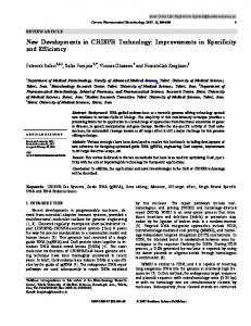
I. MICRO-CHANNEL PLATE DETECTORS. Recent measurements have achieved time resolutions ~5 ps using commercial tubes [3-4]. However, the output signals of commercial tubes are collected by multiple discrete anodes, typically with 64 to 1024 pads. The custom tube X85011 from Photonis [5] has a sensitive area of 2” x 2”, 10 micron pores and 32 x 32 anode pads. Reading each anode pad individually, would require in total 1024 channels of readout electronics. The challenge is not only to keep the tube’s fast timing performance, in the order of one to few pico-seconds resolution, in large-scale detectors, but also to have a manageable number of channels and a low power consumption of the readout electronics. As shown in Figure 1, the tube X85011, with pores at a 10 micron pitch has 1024 anode pads. Each pad is 1.1 x 1.1mm with a pitch of 1.6mm. For these tubes, a readout based on transmission lines combined with a fast analog waveform sampling would reduce by a factor of 16 the number of electronics channels without significantly degrading the tube’s fast timing performance. II. TRANSMISSION-LINE READOUT. Figure 1 shows the back of the anode plate of an X85011 tube.
Fig. 1. View of 32 x 32 anodes on the back of a Photonis custom tube X85011.
Three typical pulses measured on a beam-test with a fast sampling oscilloscope (Tektronix TDS6154C) at the Meson Test Beam facility at Fermilab are shown in Figure 2.
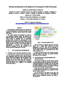
Fig. 3. The transmission lines readout card and interconnection pads to a Photonis X85011 tube with 1024 anodes, with pores at a 10 micron pitch [5].
Fig. 2. Three typical MCP pulses recorded using a fast sampling oscilloscope (Tektronix TDS6154C -20GS/s, 9 GHz analog bandwidth). The MCP has 25 micrometer pores.
Fig. 4. The readout card transmission line model used for the HyperLynx (Mentor-Graphics [7]) simulations. The characteristic impedance is 50 Ohms.
A transmission-line readout board (Figure 3) has been developed at the University of Chicago. It couples 32 anode pads in a row to a transmission line with 50 Ω characteristic impedance, read at both ends. Figure 3 shows a prototype of the transmission-line board designed to read the tube X85011. Neglecting the resistance and losses, the transmission line characteristic impedance is Z0= L / C where L and C are the inductance and capacitance per unit length of the strips. In our case, C = ε 1.6 10-3/d with ε = 3.48 ε 0. The dielectric thickness d has been tuned by the manufacturer [6] to obtain characteristic impedance as close as possible to 50 Ω . A simple first-order calculation of the propagation velocity gives c /
εr
= 1.61 108 m/s. Measurements and simulations
agree as well as can be evaluated with the measurement setup (a Tektronix DPO7354 oscilloscope). The propagation velocity is 1.75 108 m/s deduced from both the simulations in Figure 5 and measurements in Figure 6.
Fig. 5. Simulations of the propagation of the MCP pulses along the transmission lines using HyperLynx. The horizontal scale for the upper plot is 100ps/division; the scale for the lower plot is 1.5ns/division
parameters, such as the number of photo-electrons, the signalto-noise ratio, and the analog bandwidth of the input section of the front-end electronics. In the case of sampling, the resolution is estimated as a function of the sampling frequency, the number of bits in the analog-to-digital conversion, and the timing jitter of the sampling [10]. The four methods are simulated and results are evaluated with respect to each other in Figure 7. As shown, a timing resolution of a few pico-seconds is obtained with MCP detectors signals, with a number of photoelectrons above 50, corresponding to a signal over noise larger than 80. Other simulation results are presented in Table 1. A detailed description of the simulations and results is presented in [10].
Fig. 6. Measurement of the transmission line propagation velocity. The horizontal scale is 250 ps/division. The pulser rise-time is 900ps. The difference in signal paths is 3.5cm.
III. TIMING TECHNIQUES Present Micro-Channel Plate photo-multipliers and Silicon Photomultipliers (SiPMs) achieve rise-times well below one nanosecond [8-9]. Ideal timing readout electronics would extract the time-of-arrival of the first charge collected, adding nothing to the intrinsic detector resolution. Traditionally the ultimate performance in terms of timing resolution has been obtained using constant fraction discriminators (CFDs) followed by high precision amplitude digitization. However, these discriminators make use of wide-band delay lines that cannot be integrated easily into silicon integrated circuits, and therefore, large front-end readout systems using CFD's to achieve sub-nsec resolution have not been yet implemented. Several other well-known techniques in addition to constantfraction discrimination have long been used for timing extraction of the time-of-arrival of a pulse: single threshold on the leading edge, multiple thresholds on the leading edge followed by a fit to the edge shape, pulse waveform sampling followed by digitization and pulse reconstruction. In the context of this work, waveform sampling would not only allow extracting the time information with the best achievable accuracy, but also resolving ambiguities due to multiple pulses propagating through the ends of the transmission lines in a high rate environment. We have developed a Monte-Carlo simulation tool using MATLAB and translated later to C in order to generate pulses having the temporal and spectral properties of fast photodetector signals, and to simulate and compare the behavior of the four techniques described above. Both amplitude and timing resolution are estimated as a function of various
Fig. 7. Time resolution versus the number of primary photo-electrons, for the four different timing techniques: one-threshold (blue, dashed-dots), constant fraction (green, dots), multiple threshold (red, dashed), and waveform sampling (black, solid) at 40 GS/s. The analog bandwidth of the sampler is taken to be 1.5 GHz.
TABLE I TIMING RESOLUTION FOR SEVERAL TIMING TECHNIQUES
Technique Leading Edge Multiple Threshold Constant Fraction Sampling
Timing Resolution (ps) 7.1 4.6 2.9 2.3
IV. CONCLUSION AND PLANNED DEVELOPMENTS
Transmission-line readout of Micro-Channel Plate photo-multipliers allows reducing substantially the number of readout electronics channels required in large area fast photo-detectors. Combined with fast pulse sampling, low-power front ends implemented in ASICs, detectors achieving a time resolution of a few picoseconds timing and space resolutions of a few millimeters are not out of reach. The design of a prototype chip is in progress. As an intermediate step, the transmission-line architecture will be tested using a 40-GS/sec digital oscilloscope as well as off the shelf NIM constant-fraction discriminators and time-to-digital converters with a resolution of 3 pico-seconds, using a laser test stand constructed for fast-timing measurements at the Argonne National Laboratory [8]. ACKNOWLEDGMENT
We are indebted to Dominique Breton, Eric Delagnes, Stefan Ritt, and their groups working on fast waveform sampling. We thank Chin-Tu Chen, Daniel Herbst, Andrew Kobach, Jon Howorth, Keith Jenkins, ChienMin Kao, Patrick Le Du, Tyler Natoli, Rich Northrop, Erik Ramberg, Anatoly Ronzhin, Larry Ruckman, Andrew Wong, Greg Sellberg, Scott Wilbur, and Jerry Va'Vra for valuable contributions. We thank Paul Hink and Paul Mitchell of Photonis for much help with the MCP's, and Larry Haga of Tektronix for his help in acquiring the Tektronix Corporation TDS6154C 40 GSa/s sampling oscilloscope on which much of this work is based.
REFERENCES [1]
D. Acosta et al. (CDF Collaboration). "A Time-of-Flight Detector in CDF-II” Nucl. Instr. Meth. A518, 2004, pp605-608. [2] Frisch H.J. "Where We are Going in Experimental High Energy Physics?" Aspen Winter Conference. CO, 26 Jan. 2006. [3] J. Va'vra, C. Ertley, Leith, D.W.G.S., B. Ratcliff, and J. Schwiening. "A High-Resolution TOF Detector – a Possible Way to Compete with a RICH Detector" Nuclear Instruments and Methods. Submitted Dec 16, 2007. [4] K. Inami, N. Kishimoto, Y. Enari, M. Nagamine, and T. Ohshima. "A 5Ps TOF-Counter with an MCP-PMT." Nuclear Instruments and Methods A560 (2006): 303-308. SPIRES-HEP. [5] Photonis, Immeuble Circus, Hall C, Avenue Ariane Parc Cadéra Sud – CS 70019 33693 Mérignac Cedex , France [6] Rogers, One Technology Drive, Rogers, CT 06263, USA. [7] HyperLynx. Mentor-Graphics, San Jose RPI Field Office, 1001 Ridder Park Drive, San Jose, CA 95131, USA [8] C. Ertley, J.T. Anderson, K. Byrum, G. Drake, H.J. Frisch, J-F. Genat, H. Sanders, F. Tang, and J. Va’vra. “Development of Picosecond-Resolution Large-Area Time-of-Flight Systems”, SORMA 2008 Conference [9] J. Milnes and J. Howorth . “Picosecond Time Response Characteristics of Micro-channel Plate PMT Detectors” [10] J-F. Genat, G. Varner, F. Tang, H.J. Frisch. “Signal Processing for Picosecond Resolution Timing Measurements”. Submitted to Nuclear Instruments and Methods Oct 2008.