interferometer having an OPD matching that of the spectrometers [5,6] and stretched-fiber sensor, to within the source coherence length. The interferometers [7].
New Multiplexing Scheme for Monitoring Fiber Optic Bragg Grating Sensors in the Coherence Domain J.P.Dakin, Optoelectronics Research Centre, University of Southampton, SO17 1BJ, UK W.Ecke, M Rothardt, J.Schauer, K.Usbeck, R.Willsch Institute for Physical High Technology (IPHT Jena), Helmholtzweg 4, D-07743 Jena, Germany
Abstract A new multiplexing scheme for monitoring fiber optic Bragg gratings in the coherence domain has been developed. Grating pairs with different grating distances are distributed along a fiber line, and interference between their reflections is monitored with a scanning Michelson interferometer. The Bragg wavelength of the individual sensor elements is determined from the interference signal frequency.
Introduction Many methods have been devised for interrogating in-fiber Bragg gratings, including scanned filters (e.g., Fabry-Perot [1], acousto-optic [2], and stretched-fiber grating [3]), passive filters using wavelength selective couplers [4], readout spectrometers [5,6] and stretched-fiber interferometers [7]. The passive wavelengthselective filters and the acousto-optic tunable filters have the potential for fastest response, but the stretched fiber interferometer has, so far, demonstrated the greatest wavelength measurement precision. The latter can also be used in principle to read multiple arrays of gratings using Fourier transform spectrometry [8], but this usually requires significant processing time and also, in order to avoid distortions, a good quality signal, free of polarization fading. It also requires all the gratings to have different wavelengths, limiting the number possible within a given spectral range of the source.
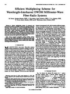
The method of coherence multiplexing [9] has been used to separate out sensors according to their optical path difference (OPD). When illuminated by a broadband source of short coherence length, each interferometric sensor in a chain shows fringe visibility only when interrogated via an optical interferometer having an OPD matching that of the sensor, to within the source coherence length. The method is sometimes termed "white light interferometry", as it is possible, in principle to use white light when path differences are very small. Principle of Bragg grating multiplexing in the coherence domain In this paper, we shall report the first work on a coherence multiplexing scheme which allows linear arrays of gratings to be interrogated by a scanned receiving interferometer. In our new interrogation system (Fig. 1) the gratings in the array are arranged as a number of in-line matched pairs with different spacings
Fig. 1 Evaluation scheme of our new coherence domain multiplexed fiber grating sensor based on pairs of Bragg gratings and scanning readout interferometer. Optoelectronics Research Centre, University of Southampton, UK
1
between each pair. A pathlength-scanned readout interferometer determines, in turn, the centroid wavelengths of each grating pair from the period of each group (burst) of visible interference fringes, formed sequentially as the scanned-interferometer pathlength passes through the path difference of each grating pair.
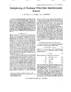
nc L2 nc L1
Fig. 2 Schematic view of the interference visibility of two grating pairs P1 and P2 during scanning (in each direction) the armlength imbalance in the readout interferometer through their spacings, L1 and L2 (nc - effective refractive index of fiber core).
However, the grating pairs act as a reflective filter, increasing the coherence length of the lightsource/grating-pair combination to approximately that of the length of the gratings. In order to avoid undesirable overlap of observed fringes from different pairs of gratings, the spacings of each pair must differ by a "decoherence" length, substantially more than the coherence length represented by the reduced spectral width. Unfortunately, the necessary differences increase if the spectrum of the broadband light source is nonideal, e.g., with residual narrow mode spectra with high-gain superluminescent diodes (SLDs). Thus, the readout interferometer selects grating pairs, sequentially, by a process of coherence multiplexing, and simultaneously measures their centroid reflective wavelengths 8B from the temporal fringe spacing, observed as it scans through. If the readout interferometer varies its pathlength linearly with time, at constant velocity vM, then the temporal fringe spacing represents an approximately constant frequency fM of fringes fM=2vM/8B.
2
Experimental results The multiplexing scheme has been tested experimentally in the arrangement of Fig. 1 with a 1300nm fiber-pigtailed SLD (SLD561) and a 1MS transimpedance receiver PRM56/4 (both from Superlum Ltd.). The Bragg grating strain sensor array consisted in the first laboratory test of two fiber grating pairs P1 and P2 , formed by UV inscription in standard single mode fiber. The length of each grating was 4mm, the reflectivity R=4..5%, the half-power bandwidth was *8=0.5nm at a mean wavelength 8B0=1305nm. Ld of the Bragg grating reflections, with bandwidth *8=0.5nm, was expected to be Ld=4q8B0²/*8 =14mm [10]. The spacing between the gratings was L1=51mm for P1 and L2=71mm for P2. However, in practice, the optical path differences 2ncqL1 (nc - effective refractive index of fiber core, nc~1.47) as well as their increments 2ncq(L2-L1) were chosen to be much longer than the decoherence length Ld of light reflected from the fiber gratings (for reasons see below). The fiber section between the grating pairs was set to be greater than 2m, to guarantee that the corresponding reflection signals would no longer contribute to interference. The Michelson readout interferometer had one fiber endface mirrored by silver coating. The optical path length of the second interferometer arm could be periodically varied: the fiber endface was reflection-free polished under an angle of 8°, the collimated light beam being reflected by a spherical retro-reflector, driven in alternating linear directions with a p-p amplitude LM=12.5mm by a push-pull solenoid pair. Separate addressing of the two sensors was performed by adjusting, sequentially, the readout interferometer to a mean retro-reflector position corresponding to an imbalance close to each of the optical pathlengths ncqL1 and ncqL2. The mean velocity of the moving mirror was adjusted to vM=LM/*t=0.55m/s. The resulting mean frequency of interference signal was typically fM =2vM/8B0 =850kHz. Small deviations *8B from 8B0 during mechanically straining (or heating) of a grating pair lead to incremental frequency changes *fM=-(*8B/8B0)qfM. For noise reduction, the interference signal at frequency fM was selectively amplified within a bandwidth of 50kHz. The frequency changes *fM were determined by
Optoelectronics Research Centre, University of Southampton, UK
counting the interference fringes at maximum interference visibility during the retro-reflector scan. Interval duration of 3ms (pass length of moving retro-reflector 1.7mm) was chosen, where the interference visibility was maximum and the velocity of the retro-reflector was nearly constant in the experiments. We expect later to employ a higher amplitude mirror scanner, to enable all grating pairs to be interrogated in one sweep. In contrast to the simplified signal shown in Fig. 2, the real system showed full decoherence only at optical path differences >50mm. This was explained by residual ripple (relative height about 10%, period 0.3nm) in the spectrum of the SLD. This caused an undesirable non-monotonous broadening of the coherence, leading in practice to the envelope of the interference signal departing from the ideal Gaussian shape. A long-periodic structure (Fig. 3) appears in the coherence function due to the few (typically 2 or 3) residual SLD Fabry-Perot modes which overlap the 0.5nm halfwidth Bragg grating reflections. The multiplexing scheme with two Bragg grating pairs was tested as a two-point strain sensor array. Tensile strain was applied immediately to the fiber leads of either grating pairs. At force levels F=0.3N, the fractional strain induced frequency change was 9q10-4/N. From this value, a Bragg wavelength shift coefficient of 1.2nm/N was calculated, in reasonable agreement with that of 1.17nm/N from direct spectral measurement [6].
Fig. 3 Interference visibility of a single Bragg grating reflection, as a function of readout interferometer armlength imbalance. The length scale is nonlinear and is given only approximately. The distance between maxima of coherence is 2.7mm, corresponding to the optical path length of the SLD chip and to the ripple period of 0.3nm in the SLD spectrum.
The absolute frequency shift was 790HzqN-1 tensile force, or 0.7Hzqµ,-1. The equivalent temperature sensor would show a frequency shift of 6HzqK-1.
Conclusion A new multiplexing scheme of fiber Bragg gratings has been developed and experimentally realized. It uses pairs of gratings with different spacings along a fiber line and with interrogation of their reflections using a scanning Michelson interferometer to separate their returns in the coherence domain. The actual Bragg wavelength of each of the sensor elements can be simultaneously determined during this scanning process by conventional frequency counting of the interference fringes. Using this technique, a resolution of strain