IEICE TRANS. FUNDAMENTALS, VOL.E00–A, NO.0 1917
1
REVIEW PAPER
Special Section on Cryptography and Information Security
New Time-stamping Scheme Using Mutual Communications With Pseudonymous Clients Akira YAMADA†a) , Shinsaku KIYOMOTO† , Toshiaki TANAKA† , and Koji NAKAO† , Members
SUMMARY Linking schemes have been proposed assuming the model where the time-stamp issuer need not be trusted. However, in that environment, a fake chain attack and forward or backward dating attacks are still a residual risk in TimeStamping services (TSS). In this paper, we propose a new timestamping scheme that focuses on these problems. In our scheme, we use pseudonyms to prevent the time-stamp issuer from dating the time that the specific entity requests. Our scheme doesn’t rely on only one trustworthy entity, and uses mutual communication between each entity. Two types of entities, server and clients without any trustworthy entities are configured in our system. The server provides an anonymous communication channel, but doesn’t provide TSS, and the clients are not only time-stamp requesters but also issuers. So, when a client requests a time-stamp from the system, it is issued by one of the other clients. key words: Time-stamp, linking scheme, forward or backward dating attack, pseudonymous, mutual communication.
1.
Introduction
Most of the time-stamping systems proposed to date are based on trusted third parties (TTP) and are, thereby, more vulnerable [9] to malicious operations by the time-stamping system itself. The key issue to be studied today is the reduction of the role of the authority. Haber and Stornetta have proposed linear linking schemes (LLS)[6] in which the time-stamps, issued by the time-stamp issuer, were linked in a one-way function such as the collision free hash function. When two time-stamped documents are given, it should be verified which of the two was created first based on the linking scheme. This scheme therefore reduces the possibilities of the time-stamp issuer operating maliciously without inverting the hash function or colluding with the clients. Although the LLS make TSS more secure, they increase the complexity of verification and still contain a residual risk of forward or backward dating attacks and a fake chain attack. As other solutions, tree-like linking schemes [1], [2], [5], [6] reduce complexity of the verification. In such schemes, time-stamping procedures are divided into rounds. All the documents requested from the time-stamp requester during the current round and previous round cumulative hash are organized as a tree. When it is verified, the required numbers of the calculating hash value are at most the logarithmic number of that submitted during the round times. However, a †
KDDI R&D Laboratories Inc. a) E-mail:
[email protected]
malicious time-stamp issuer can make a forgery of forward or backward dating. In binary linking schemes[3], [4], complexity of verification requiring a hash step is a logarithmic number of LLS. Here, the malicious timestamp issuer can also make a forgery of forward or backward dating. Considering the above situations, this paper proposes a new time-stamping scheme not only requiring a strongly trusted entity. Our approach is as follows: to prevent a time-stamp issuer from forward or backward dating of the specific time-stamp requests, our scheme uses pseudonyms as the time-stamp requester. Mix-networks[7], [8] are well known as an anonymous communication channel. However, they require at least one other server called the mix server and it knows the correspondence between the requester’s real name and pseudonym, so the server can obstruct the requester. In our scheme, the system is simply configured by clients and a server without any trustworthy entities. At first, the server gives the clients pseudonyms. When a client requests a timestamp from the system, it is issued by one of the other clients and the server behaves just as a communication channel and a monitor of injustice. At that time, although the server knows the relation between clients and their pseudonyms, the server cannot distinguish the time-stamp requester and responder. Consequently, the server cannot block the specific client’s request. The rest of this paper is organized as follows: in Section 2, we describe the current state of the art for TSSs, in Section 3, we describe the proposed scheme, in Section 4, we analyze the security of the proposed scheme, in Section 5, we discuss some issues of our scheme and we offer conclusions in Section 6. 2.
Background
2.1
Definitions of time-stamp
We define the time-stamping service and corresponding entities involved. The definitions are based on ISO documents [10]–[12], and the time-stamp issuer is newly defined here as: Time-stamping service (TSS): a service providing evidence that a data item existed before a certain point in time.
IEICE TRANS. FUNDAMENTALS, VOL.E00–A, NO.0 1917
2
Time-stamping authority (TSA): a security authority, or its agent, trusted by other entities with respect to security related activities, which provides a time-stamping service. TSA is a time-stamp responder, but the converse is not true. The responder is not quite TSA. Time-stamp requester: an entity that possesses data it wants to be time-stamped. Time-stamp issuer (responder): an entity that provides a TSS and need not be trusted by other entities. Time-stamp verifier: an entity that possesses data and wants to verify that it has a valid time-stamp bound to it. 2.2
Linear linking scheme (LLS)
Haber and Stornetta have proposed LLSs where the time-stamp issuer links all time-stamps together into a chain using a collision free hash function. Assuming that the i th submitted file Fi is requested. The timestamp is T S = (i, ti , IDi , Fi , Li ), where ti is the time when the time-stamp responder received Fi , IDi is the identifier of the submitter and Li is the linking information defined by the recursive equation Li = (ti−1 , IDi−1 , Fi−1 , H(Li−1 )). 2.3
Forward dating attack
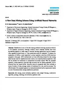
Haber and Stornetta proposed the linking schemes, under the model where time-stamp services need not be trusted. However, if we consider that no entities are to be trusted, their schemes are not completely secure [9], for example the fake chain attack or the forward or backward dating attacks. In this subsection, we redefine forward dating attack whereby our scheme targets in time-stamp services. Now, we assume a timestamp issuer is S, and some time-stamp requesters C0 , C1 , · · · , Cn−1 want to be time-stamped and send time-stamp request tokens · · · , Ri , Ri+1 , · · · , where Ri is the i th token which one of the requesters sends. Note that i means the order that the time-stamp request tokens appear in. When S receives the tokens, and S processes them in the order Pi , Pi+1 , · · ·, Pi is the i th processed token. Under the condition that the time-stamp issuer is trusted, Ri = Pi is satisfied for arbitrary i (Fig. 1(a)). The definition of forward dating attack is the existence of i that doesn’t satisfy Ri = Pi . As a time-stamp requester cannot recognize when the other requester’s token occurs, it is difficult to distinguish the timestamp issuer conducting malicious operations from regular processing. In other words, delay of a forward or
..., Ri+1, Ri, ... (a) Requesters Issuer ... , Pi, Pi+1, ... ...,Ri+1, Ri, ... ... ,Ri+1, Ri, ... Anonymous (b) Requesters Issuer Communication Channel ..., Pi, Pi+1, ... ..., Pi, Pi+1, ...
Fig. 1
Forward dating attack and its simple solution.
backward attack by the time-stamp issuer is practicable. Under the environment that all entities including the time-stamp issuer are not to be trusted, it is difficult to avoid the attacks described above. In this paper, the attack we aim to prevent is the “time-stamp issuer or any other entities that delay processing the time-stamp requesting token that a specific requester sends” and we don’t consider attacks where the time-stamp issuer operates maliciously on indiscriminate requesters. This means that malicious operation is that S identifies the client who sends the time-stamp token Rx , and S operates Py = Rx (y > x). If at least one processing order is changed, then the equation is satisfied, so we assume that the number of requests that satisfy the equation is less than n/2. In ISO/IEC 18014, the protocols do not employ identification or authentication of requesters. However, not using identifiers of the requesters is a necessary, but not sufficient condition for guaranteeing anonymity, because the possibility of a collusion of requester and TSA, linkability or traceability remains. For example, the entities communicate via the Internet as the actual model, if malicious requester reveals IP addresses of both himself and the target entity to the TSA, then TSA can identify a specific requester by means of IP address. Moreover, because IP addresses are not pseudonymous, TSA can profile and identifies the entity of specific IP address by means of packet capture or cookie techniques. After that identification, TSA can intentionally reverse the order of times-tamp tokens and the requester gets benefit illegally or suffers from a disadvantage. Unless another trusted third party guarantees the client’s anonymity such as mix-network, a TSA succeeds in the forward dating attack. 2.4
Anonymous communication channel
One of the simplest solutions to the problem described in subsection 2.3 is to use anonymous communication channels between the time-stamp issuer and requesters (Fig. 1(b)). Using the system configuration shown in Fig. 1(b), TSS is provided even if the time-stamp issuer is not a trustworthy entity. Because the communication channel indemnifies anonymity against a malicious time-stamp issuer, the time-stamp issuer cannot know who requests the time-stamp. The malicious operator cannot issue delayed time-stamps to specific requesters. However, this system configuration is based on the as-
YAMADA et al.: NEW TIME-STAMPING SCHEME USING MUTUAL COMMUNICATIONS WITH PSEUDONYMOUS CLIENTS
3
sumption that the operations to guarantee anonymity of the communication channel are properly performed. If not, there is the probability that anonymity is not guaranteed. Mix-network is famous as an anonymous communication channel. Mix-network is a multi-party protocol consisting of a set of so-called mix servers, who take a list of cipher texts and collectively produce and output a permuted list of items. Here, the output items are either plaintexts that correspond to the input ciphertexts, or ciphertexts that correspond to the same plaintexts as the input ciphertexts. The important functionality of a mix-network is that as long as at least one of the mix servers is honest, the privacy of the output is guaranteed. This means that if there are no honest mix servers, a mix server can specify who sends the requesting token. Therefore, the malicious mix server can block or delay the specific requester’s token. Considering TSSs include a communication channel, though the authorities involving TSS are decentralized and the chances of being attacked become smaller, the model where TSS need not be trusted is not completely achieved. There is a residual risk that the anonymous communication channel is operated dishonestly. 2.5
Our goals
The linking schemes still have several problems within the practical implementation. Under the delay condition in the communication channel, it is basically difficult for the requester to distinguish forward or dating attacks from simple network delay because a requester cannot recognize when it is received. The aim of proposing the linking scheme is to guarantee that no matter how unscrupulous the time-stamp issuer is, the times it certifies will always be correct, and it will be unable to issue incorrect time-stamps even if it tries to. In other words, if the time-stamp issuer is really trusted and issues the time-stamp honestly, then the effects of linking schemes are few. Assuming that the time-stamp issuer need not be trusted, the linking schemes don’t prevent forward dating of the time-stamp issuer. Even if the time-stamp issuer doesn’t respond immediately, the time-stamp requester can’t discern from the network latency. Therefore, our main goal is to realize a digital time-stamp scheme that satisfies the following requirements: 1. not dependent on one trusted entity and 2. prevents forgery of time (including forward dating) under the condition that network latency is introduced. The first goal means that if one strongly trustworthy entity exists, then linking schemes are not required; otherwise, it should be assumed that no entities are to be trusted. The second goal means that in a real network, such as the Internet, network latency is a mea-
surable value. To apply a practical network, network latency has to be considered. 3.
Proposed scheme
3.1
System configuration
Our proposed scheme is constructed simply of a server S and clients Cx (x = 0, 1, · · · , n − 1). S and Cx are connected by a communication channel, in which, any data can be sent and positively received, but latency resides. The latency value can be defined as the elapsed time (delay) between the generation of a query at a sender and its realization at a receiver. And its value is randomly between dmin and dmax . Where dmin is the minimum value and dmax is the maximum. Each entity is defined as follows: server S: S fills three roles of this time-stamp system. First is registering the client, second the anonymous communication channel, and third the warder, which watches for Cx malicious response. But as S is not strongly trusted, this means that the specific client’s request may be delayed(forward dating attack). client Cx : Cx becomes not only the time-stamp requester but also the time-stamp responder. That is to say, at one moment Cx , it requests a time-stamp token and at another moment, it responds with (issues) a time-stamp token. There is the possibility that responding with a specific client’s time-stamp may be delayed. 3.2
Proposed scheme
Most time-stamping systems that have been proposed are based on Client/Server architecture, so a client sends a time-stamp request and a server replies with a time-stamp response. Where the time-stamp responder and time-stamp requester are the server and the client, a time-stamp verifier, which the client and the server can also be, gets information from the requester and responder and then, verifies the time-stamp. On the other hand, our proposed scheme uses mutual communication between clients, where a client plays roles of both time-stamp requester and responder. The roles of the server are managing the client’s registration, the gateway of that communication and watching client’s behavior. We show the difference between the proposed scheme and former schemes in Fig. 2. When a client requests or responds with a time-stamp in our scheme, it is necessary that the server register the clients and then the clients have to communicate with all other clients periodically. In the following section, we describe registering protocol, the protocol of standing by, timestamp requesting and responding protocol and timestamp verifying protocol. In Fig. 3, we show diagrams of each protocol from the perspective of a client.
IEICE TRANS. FUNDAMENTALS, VOL.E00–A, NO.0 1917
4 Table 1
Server (Gateway)
Server (Responder) asdfasdfasdf adsfasdfasdf asdfasdfsadf
…
…
Time Stamp 2001,12,10
…
request
asdfasdfasdf adsfasdfasdf asdfasdfsadf
asdfasdfasdf adsfasdfasdf asdfasdfsadf
Time Stamp 2001,12,10
…
asdfasdfasdf adsfasdfasdf asdfasdfsadf
request
response
Client (Requester)
response
Client (Requester)
(a) Conventional Schemes.
The table made by server.
released Temporary ID public key 0 1 .. .. . . T IDx Kp,x .. .. . . n-1
Client (Responder)
not released ID
.. . IDx .. .
(3) Assign temporary ID and make the table.
(b) Proposed Scheme. (2) Kp,0 ID0
Fig. 2 Difference between conventional schemes and proposed scheme.
... ...
registration
stand by
Client C0 Kp,0 Ks,0 (1) ID0
renewal of key pair
Fig. 4
request
Fig. 3
C1 Kp,1 Ks,1 ID1
Cn-1 Kp,n-1 Ks,n-1 IDn-1
Registration protocol.
Diagram of each protocol from the perspective of clients.
don’t know who possesses the temporary ID unless they know the ID. 3.3
Registration protocol
We denote public key, private key, ID, and temporary ID of Cx as Kp,x , Ks,x , IDx and T IDx respectively. ID is the number to identify the Cx and is uniquely assigned in advance. If an entity knows the other entity’s ID, then he can know who possesses that. In that case, a malicious client may deny the request for the specific client. To avoid this problem, a temporary ID is introduced. T IDx is the pseudonyms that the server assigns to a registered client. We assume that a communication channel between Cx and S is secure. This assumption means that if Cx sends a message to S, then it is not disclosed to any other unauthorized clients, and Cx and S can also identify who sends or who receives. As another assumption, S and Cx can obtain an accurate time constantly and their times are synchronized. 1. Cx generates a key pair that the public key Kp,x and the private key Ks,x . 2. Cx sends Kp,x and IDx to S. 3. S assigns T IDx (0 ≤ T IDx ≤ n − 1) which is a temporary ID in the received pairs Kp,x and ID, then, S makes the public key certificate of the public key Kp,x , and updates the table shown in Tab.1. Note: Cx can only know the values of the released columns in Tab. 1; on the other hand, S can know all the values including those columns not released. In other words, only S knows the unreleased values. The clients recognize each other by the temporary ID and
3.4
Standing by protocol
Registered clients communicate with each other in the standing by period for the time-stamp requesting and responding. A client Cx communicates with all the other clients Cy (y ̸= x). The communications occur periodically after registration of the clients. Now Cx sends a token T Si (x, y) to Cy . The protocol is shown in the following, as illustrated in Fig. 5, where i is the sequential number indicating the order of communications between Cx and Cy , and the next token from Cx to Cy is T Si+1 (x, y). 1. A client selects another client excluding himself from Tab.1, the chosen client is Cy , and its public key, private key, ID and temporary ID are shown with Kp,y , Ks,y , IDy and T IDy . Note that Cx can know only Kp,y and T IDy . 2. Cx sends T Si (x, y) to S. Where T Si (x, y) = {T IDx , T IDy , Es,x (Ui ), Ui }, Ui = {tx , Ep,y (Dx,i , Dy,i−1 )}, Es,x () denotes signature with a private key Ks,x . Ep,y () denotes encryption with Kp,y , and Dx,i denotes data payload of Cx . tx denotes local current time of Cx . Cx stores Dy,i−1 , which is the data payload of the former communication T Si−1 (y, x). 3. S locates IDy , which corresponds to T IDy by searching Tab.1. Then, S sends T Si (x, y) to the client who has corresponding IDy .
YAMADA et al.: NEW TIME-STAMPING SCHEME USING MUTUAL COMMUNICATIONS WITH PSEUDONYMOUS CLIENTS
5
(3) Convert TIDy to IDi and deliver TSi (2) TSi={TIDx, TIDy, Es,x(Ui), Ui} Ui={tx, Ep,y(Dx,i, Dy, i-1)}
TSi
Cy Kp,y Ks,y IDy
Client Cx Kp,x Ks,x IDx (1) Select other client
Fig. 5
Communication of standing by.
3.6
Verification protocol
Assume that a verifier has F, Dres,i−1 they want to verify and their time-stamp T Si (res, req). We denote the protocol to verify whether T Si (res, req) is a proper time-stamp of F .
1. The verifier calculates the hash value H(F ) from F. 2. The verifier calculates Ui = {tres , Ep,req (Dres,i−1 , H(F ))} using Kp,req , which is referred to in Tab.1. 3. The verifier verifies the signature Es,res using Kp,res , which is referred to in Tab.1. 4. If the signature is valid, T Si (res, req) is valid timestamp binding of the time value tres with the file F.
(3) Send H(F) taking place of Dreq TSi={TIDreq, TIDres, Es,req(Ui), Ui} Ui={treq, Ep,res(H(F), Dres,i-1)}
Client Creq Kp,req Ks,req IDreq Requester
Fig. 6
3.5
(1) Calculate H(F) (2) Select the responder Cres.
Cres Kp,res Ks,res IDres Responder
Requesting and responding protocol.
Requesting and responding protocol
Now we newly defined Creq and Cres as the client who requests and responds a time-stamp respectively instead of using Cx and Cy . 1. A requesting client Creq calculates H(F ), where H() is a collision free hash function and F is the message to be time-stamped. 2. Creq selects a responding client Cres from the Tab.1 who receives time-stamp request. 3. At the regularly communication, Creq sends T Si (req, res), in which data payload, H(F ) instead of Dreq,i is stored. When the client Cres receives the time-stamp request, Cres doesn’t need special treatment. Cres has only to send T Si+1 (res, req) which contains H(F ) to Creq at the next transaction in the same way as when he is standing by. In the first place, Cres can’t distinguish data payload Dreq,i from H(F ). It means that Cres doesn’t recognize whether he responds to the timestamp request or not. Thus, the time-stamp of file F is T Si+1 (res, req).
4.
Security Analysis
4.1
Renewal of temporary ID and the key pairs
In the proposed scheme, temporary ID and key pairs of clients are renewed regularly. In this procedure, the server must publish the pair of the temporary ID and its corresponding ID, where only the server publishes and manages this information. Therefore, the renewal procedure prevents an attack such that the server counterfeits clients. 4.2
The roles of server
The roles of a server are managing the registering of clients, gateway of that communication and watching client’s behavior. In this subsection, we describe the procedure where the server watches clients. First, the server links all T Si (x, y) together into a chain using a collision-resistant hash function H such as a linking scheme. Then, the server publishes the hash values in the bulletin board regularly. By server linking, the proposed scheme becomes more secure. The server confirms whether the difference between the time tx contained in T Si (x, y), and the time tS that the S receives T S is within the threshold Tth,min < tS − tx < Tth,max , where Tth,min , Tth,max are defined before the protocol starts. If the difference is less than the threshold, then the communication is normally terminated. Otherwise, the server broadcasts tS and tx to prove injustice of the client Cx . Regarding the data integrity, tS is signed by the server.
4.3 Resistance to forward dating attack T Si+1 (res, req) = {T IDres , T IDreq , Es,res (Ui+1 ), Ui+1 }, We suppose that n clients forward a time-stamp prepaUi+1 = {tres , Ep,req (Dres,i+1 , H(F ))}. ration token to each other and each client sends m tokens and the r(m > r) time stamp requests every
IEICE TRANS. FUNDAMENTALS, VOL.E00–A, NO.0 1917
6
second. We assume that tokens sent by each client occur independently. Now, the probability that a token is r time-stamp requested is Pr (= m ), which is uniform distribution, and a client randomly selects another client as the issuer of the time-stamp. On this assumption, we derive the probability that the attack is successful. At first, we consider that the malicious server interferes in the transaction from the victim client. In subsection 2.3, we assume that the server doesn’t attack indiscriminate clients, and we define forward dating attack as any entities that later change the order of a specific client’s time-stamp token. The probability of a time-stamp token including a time-stamp request is Pr , the probability of a time-stamp token being sent to a victim client that includes a time-stamp issued by the other clients is Pr . The probability of a time-stamp token being sent to a victim client not including a time-stamp request of the other client is 1 − Pr . Therefore, the probability of successful attack is (1 − Pr ) · Pr . When the malicious server is blocked for s seconds, it is probable that it blocks at least one requesting token from a victim client with no interruption of any other issuing token for a regular client.
tm
ts (4) dmin
tx
ts
(2)
(3)
dmin
2dmin
dmax
tx
∆T ∆T
dmax 2dmax
dmin (4) dmax
(a) The Conditions that Cx can recognize (b) A manipurate within ∆T may injustices of S or Cm. satisfy the condition eq. (4). Fig. 7
Relation among tS , tx and tm .
tS − tm < dmin or dmax < tS − tm .
(4)
If S responds always correctly, (2) must not satisfied. Namely the condition is as follows: dmin ≤ tx − tS ≤ dmax .
(5)
But the inverse is not true. Therefore, even if S manipurates the tS within ∆T , (5) may be satisfied (Fig.7(b)) and Cx may not recognize the maliciousness. ∆T = dmax − dmin . Therefore (4) is transformed in consideration of injustice within ∆T (Fig.7(c)).
P = (1 − Pr )m·s · {1 − (1 − Pr )m·s }, r r = (1 − )m·s · {1 − (1 − )m·s }. m m
(1)
tS − tm < dmin − ∆T or dmax + ∆T < tS − tm .(6)
The probability shown in (1) approaches 0 as r increases. Therefore, the probability of the attack succeeding is negligible. The case where a malicious server interferes with the transaction to a victim client has equivalent probability. For example: r = 10, m = 1000 [times/sec.], and s=1 [sec.].
On the other hand, because tm is signed by Cm , S can’t manipulate tm . Considering network latency, (3) is transformed into
P = (1 − 0.01)
1000·1
· {1 − (1 − 0.01)
1000·1
−5
} ≈ 4.32 · 10
.
tS −tm < 2dmin −dmax or tS −tm > 2dmax −dmin .(7) So, the thresholds Tth,min , Tth,max are derived from (6) and (7). Tth,min = 2dmin − dmax , Tth,max = 2dmax − dmin .(8)
5.
Discussion
5.1
How to define the threshold of latency
5.2
We derive the threshold of latency which is described in section 4.2. The server S receives a time-stamp token T S(), which contains injustice time tm from a malicious client Cm at the time tS . S calculates the difference tm − tS . If the difference isn’t in the threshold: Tth,min < tm −tS < Tth,max , then S broadcasts tm , tS to all clients. And a client Cx receives tm , tS at the time tx and verifies. Now, we derive the conditions that Cx discriminates injustice of Cm even if low level trust S is suspected. The conditions where Cx can recognize injustices of S or Cm are (2), (3) or (4) (Fig.7(a)). tx − tS < dmin or dmax < tx − tS , tx − tm < 2dmin or 2dmax < tx − tm ,
(2) (3)
Trust levels
ISO 18014-3 states that producing linked tokens provides verifiable cryptographic binding between a certain point in time and data values, and enhances the security of the resulting tokens by reducing the trust level required in the TSA. This means that there are different trust levels of a TSA, and linking schemes require a lower trust level. Now, we define trust level as follows: Level 3: The entity is trusted by the other entities with respect to all security related activities. Level 2: The entity is trusted between the time points when receives and when responds with respect to the activities related to the request. In other words, the entity compounds the linking structure properly.
YAMADA et al.: NEW TIME-STAMPING SCHEME USING MUTUAL COMMUNICATIONS WITH PSEUDONYMOUS CLIENTS
7
Level 1: Under the condition that the entity cannot identify the target entity, the entity is trusted between the time points when receives and when responds with respect to the activities related to the request. In other words, even if the entity is malicious, he will play the role for indiscriminate requesters. Level 0: The entity is not trusted by other entities with respect to all security related activities. Level 3 is high and level 0 is low trust conditions, and the TSA of linking schemes require the level 2 and the server of our scheme requires the level 1. Moreover the server cannot differentiate request tokens from response tokens in our scheme.
6.
Conclusion
We presented a new scheme for the digital timestamping system without strongly trustworthiness of the TSA or other trusted entities. The scheme is based on the system configuration, which consists of clients and a server. Any client can request a time-stamp and simultaneously respond to it, and the server only behaves as a monitor of injustice in the communication channel. Consequently, based on our scheme, vulnerability of the forward dating attack is successfully removed, and the burden of responsibilities on trustworthiness in the time-stamping systems is well decentralized and distributed to each client. References
5.3
Application
We discuss an application of our new scheme. Our scheme is more decentralize than that had been proposed. The features reduce the possibility of the attacks including the forward dating attack. Although our scheme requires lower level trust, some conditions to implement real applications are taken into consideration. Namely, clients need to issue response tokens incessantly to answer the request during the service. This means that the clients need to have heavy computational power, and wider network bandwidth is also required for periodical communications of each client. Therefore, there is a tradeoff between regarded computational power of the clients and trustworthiness of TSA required. Namely, we have to design time stamping scheme depending on a specific application scenario. As an application scenario, our scheme is also suitable for the following multiple TSA applications. In the application, there are some time stamping services that have been provided independently, and each TSA are managed by different organization. In the situation, it is a problem how the service cooperates with the other service across the different time-stamping organization. Because TSA has an enough computational power and a lower level trust at least, our scheme can be easily applied to the multiple TSA application where each TSA corresponds to the client of our scheme. The other point to realize the service is the number of the clients. The security of our scheme depends on the face that TSA cannot differentiate request tokens from dummy tokens. Intuitively, our scheme seems not to be effective under the condition that the total number of the clients is very small. However, we derive that the probability of a forward dating attack doesn’t depend on the number of clients in subsection 5.2. Therefore, the probability and its parameters are practical, even though the number of clients is less than other schemes, assuming that the number of the tokens to be sent at a certain period in time is large enough.
[1] D. Bayer, S. Haber and W. S. Stornetta, “Improving the Efficiency and Reliability of Digital Time-Stamping.” Sequences’91: Methods in Communication, Security, and Computer Science, 1992, pp. 329–334. [2] J. Benaloh and M. de Mare, “Efficient Broadcast timestamping.” Technical Report 1, Clarkson University Department of Mathematics and Computer Science, 1992. [3] A. Buldas and P. Laud, “New Linking Schemes for Digital Time-stamping.” The 1st International Conference on Information Security and Cryptology, 1998, pp. 3–14. [4] A. Buldas, P. Laud, H. Lipmaa, J. Villemson, “Timestamping with binary linking schemes.” Advances in Cryptology – CRYPTO 98 1998, pp. 486–501. [5] S. Haber and W. S. Stornetta, “Secure Names for BitStrings.” Proc. 4th ACM Conference on Computer and Communications Security, 1997, pp. 28–35. [6] S. Haber and W.S Stornetta, “How to time-stamp a digital document.” J.Cryptology, 1991, pp.99–111. [7] M. Jakobsson, “A Practical Mix.” Advances in Cryptology – EUROCRYPT ’98, 1998, pp. 448–461. [8] M. Jakobsson, “Flash Mixing.” Symposium on Principles of Distributed Computing, 1999, pp. 83–89. [9] M. Just, “Some TimeStamping Protocol Failures.” Internet Society Symposium on Network and Distributed System Security, 1991. [10] ISO/IEC 18014-1:2002, Information technology – Security techniques – Time stamping services – Part 1: Framework. [11] ISO/IEC 18014-2:2002, Information technology – Security techniques – Time-stamping services – Part 2: Mechanisms producing independent tokens. [12] ISO/IEC FCD 18014-3, Information technology – Security techniques – Time stamping services – Part 3: Mechanisms producing liked tokens.