Chapter 6
Next Generation of Engineering Methods and Tools for SOA-based Large-scale and Distributed process applications Robert Harrison, C. Stuart McLeod, Giacomo Tavola, Marco Taisch, Armando W. Colombo, Stamatis Karnouskos, Marcel Tilly, Petr Stluka, François Jammes, Roberto Camp, Jerker Delsing, Jens Eliasson, J. Marco Mendes
Abstract Engineering methods and tools are seen as key for designing, testing, deploying and operating future infrastructures. They accompany critical processes from “cradle-to-grave”. Here we provide an overview of the user and business requirements for engineering tools, including system development, modelling, visualisation, commissioning and change in an SOA engineering environment. An appraisal of existing engineering tools appropriate to IMC-AESOP, both commercial and development prototypes are presented, culminating in the presentation of tool
Robert Harrison, Stuart McLeod University of Warwick, UK e-mail:
[email protected],
[email protected] Giacomo Tavola, Marco Taisch Politecnico di Milano, Italy e-mail:
[email protected],
[email protected] Armando W. Colombo Schneider Electric & University of Applied Sciences Emden/Leer, Germany e-mail: armando.
[email protected],
[email protected] Stamatis Karnouskos SAP, Germany e-mail:
[email protected] Marcel Tilly Microsoft, Germany e-mail:
[email protected] Petr Stluka Honeywell, Czech Republic e-mail:
[email protected] François Jammes Schneider Electric, France e-mail:
[email protected] Roberto Camp FluidHouse, Finland e-mail:
[email protected] Jerker Delsing, Jens Eliasson Luleå University of Technology, Sweden e-mail:
[email protected],
[email protected] J. Marco Mendes Schneider Electric, Germany e-mail:
[email protected]
1
Harrison et al. 6.1. Introduction
cartography graphically, defining the impact of these tools within the enterprise and system lifecycle.
6.1 Introduction Engineering of a new generation of very large-scale SOA-based distributed systems for batch and continuous process applications requires a new generation of methods and tools. They need to support the lifecycle (e.g., design, configuration, management and support) of new SOA-based system architectures, which must provide SCADA functional capabilities to meet user requirements for much greater distributed control and decision-making abilities than current DCS system implementations. Some 50% of the DCS platforms running process plants today are at least 20 years old with a large number of these at the end of their lifecycle. They typically contain a mishmash of technology, which in turn requires a wide range of ad-hoc engineering tools and methods to support them, limiting integration both vertically and horizontally and making reconfiguration of systems, or their optimisation, difficult to achieve effectively. There is a growing need to meet various migration requirements for both small and large system configurations in an efficient manner, and this capability, to be provided via the identified core IMC-AESOP technology, needs to be supported via specific engineering tools. The shift from systems implemented via a predominantly centralised paradigm to control and monitoring strategies based on a system of systems engineering approach [16, 15] with thousands of dynamic SOA-compliant devices requires a new engineering methodology with requirements for new modelling and engineering approaches in order to enable such systems to be practically realised. The approach adopted on the IMC-AESOP project was driven by user requirements derived from the studied use cases. These determined the required tools for the considered SOA process control application(s), from which a tool cartography has been created, as described in this chapter. In areas where suitable existing tools either did not exist or lacked adequate functionality, new tools were developed or existing ones extended to meet the requirements of the use cases. These are detailed in section 6.3 along with the requirements they fulfil, how they were implemented, and the results they produced. The IMC-AESOP project has addressed the issues of DCS across differing industrial/business domains, as highlighted by the different use cases, from real-time lubrication of mining machinery to heating management systems and district-heating applications. The requirements of these applications are broad, and the engineering content in each varies significantly. However, Section 6.4 describes how each of the tools is used and categorises them as per their architectural level for each use case. Finally the IMC-AESOP toolkit is identified, highlighting the tools recommended to build the selected applications.
2 This is a preprint version, which may deviate from the final version which can be acquired from https://www.springer.com/gp/book/9783319056234
Harrison et al. 6.2. Engineering Methods and Cartography of Identified Tools
6.2 Engineering Methods and Cartography of Identified Tools The first activity constitutes the identification of tools and methods that are relevant to the needs of the project, based on a study of the state of the art in engineering tools and methods for the development and support of SCADA and DCS systems. An overview is provided of the user and business requirements for engineering tools, from the SOA, system modelling and change management, application and device design development and support perspectives. System simulation, visualisation, commissioning and optimisation were also considered, together with an overview of system-of-systems engineering from a tools and methods perspective.
6.2.1 SOA engineering methods The engineering of distributed embedded systems requires the modelling and support of units of distributed functionality. Object-based specifications emphasize structural decomposition, which facilitates the implementation of open and reconfigurable systems, whilst industrial software standards such as IEC 61131-3 [4] provide mechanisms for functionally decomposing and programming and IEC 61499 [6] describes the modelling of communicating distributed function blocks. In this case a system can be described as a composition of interacting components, such as function blocks or port-based objects, which are then mapped onto real-time tasks. Object and function-block based design uses a number of fundamental principles such as encapsulation, aggregation and association of objects or components to build applications. However, whilst object- and component-based system software development is well established in several domains, a major problem that has to be overcome is the current informal and largely ad-hoc definition of application components. Ad-hoc specification and design may severely limit component reusability. Therefore, it is highly desirable to develop a formal framework that will allow for a systematic specification of reconfigurable components, which will be reusable by definition. Such factors needed careful consideration in the realisation of the IMC-AESOP system architecture and middleware which promote the building of applications comprising interacting components from device level up to enterprise level.
6.2.2 System modelling, evolution and change management In order to implement a smooth and consistent transition from a SCADA environment developed via a classical (and often inhomogeneous and improvised) approach on proprietary, obsolete and rigid platforms into an open, standard, serviceoriented one, appropriate tools need to be realized for system modelling, evolution and change management. 3 This is a preprint version, which may deviate from the final version which can be acquired from https://www.springer.com/gp/book/9783319056234
Harrison et al. 6.2. Engineering Methods and Cartography of Identified Tools
The concept of application engineering tools needs to be considered in a broad context including methodologies and soft skills in addition to the technological aspects. • From the system- and information-modelling perspectives support is needed for the following: – A representation of the industrial environment with a standard recognized syntax. – The enrichment of models with related information as parameters, semantic information, links with other objects and conditional functionalities. – The definition of a hierarchy (taxonomy). – An easy transposition in service architecture approach with automatic translation into XML syntax of metadata. • Support for system change-management and evolution-management tools, although beyond the scope of IMC-AESOP, are crucial for effective lifecycle engineering. The management of change encompasses activities beyond data management, including people management, motivation and the ability to identify key factors in complex environments.
6.2.3 Application design Engineering tools to support the design of automation applications need to be implemented in order to maximise the capabilities offered by the technological solutions implemented at the shop floor level; this includes, but is not limited to, machine mechanical modular design, distributed plug-and-play control systems, interfacing to TCP-based networks and high level process management systems (e.g., ERP and SCADA), as well as remote maintenance and monitoring systems, and support for reusability and reconfigurability for effective design-change management.
Fig. 6.1 Automation System Design – Tool design requirement
4 This is a preprint version, which may deviate from the final version which can be acquired from https://www.springer.com/gp/book/9783319056234
Harrison et al. 6.2. Engineering Methods and Cartography of Identified Tools
In summary, key aspects of application engineering tool capabilities are the following: • Reconfiguration: Configuration and change of the application by the user. • Process description and validation: Control application defined in the user’s terms. • Device support & maintenance: Support for embedded device. • Real-to-virtual connectivity: Integration with virtual engineering. • Process-to-business connectivity: Integration with business and production monitoring/support applications.
6.2.4 Device development and support Using SOA on embedded devices down on the factory floor can enable powerful cross-layer possibilities. However, SOA protocols, originally developed for the enterprise domain impose heavy restrictions on their usage on resource-constrained embedded systems. This is especially true in the context of a Wireless Sensor and Actuator Network (WSAN). The relatively low bandwidth of a wireless network is a limiting factor for network performance when sensing very large packets. The commonly used protocol today for SOA in industrial automation is SOAP, using the verbose XML language. The use of XML drastically increases the size of a message containing sensor data. However, XML has excellent support today from a large number of software vendors, which makes it an open and standardized way to exchange data between devices from different manufacturers using different operating systems and applications. One benefit of the SOA approach is that message parsers can be automatically generated for each message class. This reduces the need to manually write software for the serialisation of messages. Today, the two most widely used operating systems for wireless sensor and actuator networks are TinyOS from University of California in Berkeley, and Contiki from the Swedish Institute of Computer Science, Stockholm, Sweden. Research is currently being performed by researchers in both academia and the industry to move SOA technology down to sensor node level. The application of a widely used operating system combined with auto-generated message parsers enables system developers to re-use the existing code base to a large extent and mitigates the need to develop proprietary communication protocols. Today, gSOAP is a commonly used, proven, and stable tool to generate XML parsers. New solutions based on binary XML, i.e. EXI, need new tools to be developed. The use of EXI will be an enabling technology for SOA-based wireless sensor and actuator networks.
5 This is a preprint version, which may deviate from the final version which can be acquired from https://www.springer.com/gp/book/9783319056234
Harrison et al. 6.2. Engineering Methods and Cartography of Identified Tools
6.2.5 Simulation System simulation is advantageous both at design time and during the operational phase. Simulation capabilities (i.e. the capabilities to simulate the time-dependent, dynamic system behaviours) can potentially provide strong support for testing various aspects of the system design in a virtual form prior to its final implementation in order to minimise design errors and compress design time. Simulation capabilities need to be provided for, and adapted to, each engineering application that the system design involves (e.g. control, process, and mechanical) as shown in Fig. 6.2. However, domain-dependent simulation capabilities should be integrated in a form that will enable multi-disciplinary engineering teams to assess the level of completion and quality of their specific design with regard to the characteristics and behaviours expected of the final system.
Fig. 6.2 Overview of simulation capabilities of automation system design tools
6.2.6 System visualisation Application tools that provide system visualisation capabilities are typically user or domain specific, i.e. they provide a representation of the system focused on the requirements of a specific end user or domain of activity. For example, a process automation system will be perceived differently by control, process, electrical or mechanical engineers, and the tools used to visualise the system need to be specifically designed to their requirements, as illustrated in Fig. 6.3. Simulation, visualisation and system engineering applications are typically tightly linked so that visualisation tools provide both static and dynamic system representations during the system design phase. Visualisation tools should provide userspecific views of a system. However, a common, intuitive, non-specific representation of the system to support cross-domains engineering collaboration and general communication between project partners is also needed. 6 This is a preprint version, which may deviate from the final version which can be acquired from https://www.springer.com/gp/book/9783319056234
Harrison et al. 6.2. Engineering Methods and Cartography of Identified Tools
Fig. 6.3 Automation system Visualisation tool
3D computer graphic representations are typically used to implement common visualisation models of physical systems such as automation systems since a 3D virtual system representation provides a view of the system as perceived by the human physiological sensory system (i.e. sight) as opposed to the specific mental images that various engineers might have of the system. Domain-specific system visualisation tools might make use of very different representations (e.g. IEC 61131-3 for PLC control logic, state transition diagrams and Petri-net based representations for discrete system behaviour visualisation, and flow-based chart/graphs for continuous system visualisation).
6.2.7 System commissioning The commissioning of a plant is a specific phase in the lifecycle. In this phase, the equipment, especially the field devices, will be installed and adapted to the real process requirements. Important tasks during commissioning include the identification of the devices, including the device type information, and setting the correct instance information, e.g. the tag names of the devices. Commissioning may be subdivided into offline and online configuration activities. The offline configuration can be started directly after the instrumentation is defined, capturing the types of the required devices, their placement inside the plant and their addresses. Functional information is required for device configuration. Typical technologies providing such information, for offline as well as online configuration, are the Electronic Device Description Language (EDDL, IEC 61804-3)[22, 8], Field Device Tool (FDT, IEC 62453) [7] or the upcoming approach of Field Device Integration (FDI).
7 This is a preprint version, which may deviate from the final version which can be acquired from https://www.springer.com/gp/book/9783319056234
Harrison et al. 6.2. Engineering Methods and Cartography of Identified Tools
Fig. 6.4 Levels of Interoperability [2]
6.2.8 Interoperability In order to build distributed control applications the components of a system need to communicate successfully. Engineering tools are required to support this integration, and where direct interaction is not possible, then wrappers and mediators must be employed. Fig. 6.4 illustrates the levels of interoperability from no interoperability and technical interoperability at the network level through syntactic, semantic and pragmatic interoperability at the application level, to dynamic and conceptual interoperability at the modelling level. Each of these is described below [2]. • Level 0: Stand-alone systems have No Interoperability. • Level 1: On the level of Technical Interoperability, a communication protocol exists for exchanging data between participating systems. Here the communication of simple data is achieved with the network protocols being unambiguously defined. • Level 2: The Syntactic Interoperability level introduces a common structure to exchange information, i.e., a common data format is applied. On this level, a common protocol to structure the data is used; the format of the information exchange is unambiguously defined. • Level 3: If a common information exchange reference model is used, the level of Semantic Interoperability is reached. On this level, the meaning of the data is shared; the content of the information exchange requests are unambiguously defined.
8 This is a preprint version, which may deviate from the final version which can be acquired from https://www.springer.com/gp/book/9783319056234
Harrison et al. 6.2. Engineering Methods and Cartography of Identified Tools
• Level 4: Pragmatic Interoperability is reached when the interoperating systems are aware of the methods and procedures that others are employing. In other words, the use of the data or the context of its application is understood by the participating systems; the context in which the information is exchanged is unambiguously defined. • Level 5: As a system operates on data over time, the state of that system will change, and this includes the assumptions and constraints that affect its data interchange. If systems have attained Dynamic Interoperability, then they are able to comprehend the state changes that occur in the assumptions and constraints that others are subject to over time, and are able to take advantage of those changes. In particular when interested in the effects of operations, this becomes increasingly important; the effect of the information exchange within the participating systems is unambiguously defined. • Level 6: Finally, if the conceptual model is a meaningful abstraction of reality, the highest level of interoperability is reached: Conceptual Interoperability. This requires that conceptual models be documented based on engineering methods enabling their interpretation and evaluation by other engineers. In other words, on this we need a “fully specified but implementation independent model” and not just text describing the conceptual idea.
6.2.9 Cartography of identified tools Within the IMC-AESOP project a study was carried out to compare practically available enabling technologies for application systems engineering, which might be utilised within the scope of the project. The coverage takes a selective and critical look at available candidate engineering tools. Summaries of the strengths and weaknesses of the evaluated engineering tools provide a broad indication of their capabilities against selected criteria for control, enterprise integration, supply-chain/lifecycle support, and virtual engineering. This information was helpful in understanding what aspects of current toolsets were applicable in the context of the project use cases. As a result of this study, tools suitable for use on the IMC-AESOP project were identified. As can be seen in Fig. 6.5 above, the coverage of the tools is potentially sufficient to allow the whole lifecycle and all architectural levels to be supported. There is, however, a large amount of overlap between many of the tools, and support is highly fragmented. It should be noted that this overlap does not necessarily imply duplication, as different aspects (either complimentary or unrelated) may be covered. Table 6.1 describes the selected engineering tools that were subsequently identified for use in IMC-AESOP.
9 This is a preprint version, which may deviate from the final version which can be acquired from https://www.springer.com/gp/book/9783319056234
Harrison et al. 6.3. Prototypes of critical tools, including system modelling and analysis methods
Fig. 6.5 Overview of Tool Cartography
6.3 Prototypes of critical tools, including system modelling and analysis methods Based on the analysis of the requirements of the IMC-AESOP use cases against the tool capabilities described in section 6.2, critical new tools or tool-extensions were identified and developed within the project. In particular: 1. 2. 3. 4. 5. 6. 7. 8.
EXI Compression. See section 4.2.2 Ignition SCADA OPC-UA API. See section 4.2.4 Electric car charging optimiser. See section 9.3.2. Orchestrators. See section 9.3.2 Service bus configurator. See section section 7.3.3 Aggregations services. See section 9.2.3 Process Definition Environment, PDE toolkit. See section 10.3 Continuum. See section 10.3
The following sub-sections briefly review the emerging tool developments undertaken on the project highlighting the requirements addressed, the implementations undertaken, and the results achieved.
10 This is a preprint version, which may deviate from the final version which can be acquired from https://www.springer.com/gp/book/9783319056234
Harrison et al. 6.3. Prototypes of critical tools, including system modelling and analysis methods
Table 6.1 Engineering tools Name
Description
Control Build Applica- Control Build is dedicated to the needs of control systems engition Generator neers, providing standards-based (IEC 61131-3) programming languages and integration into HMI/SCADA systems; it is positioned well for PLC / distributed system development[11] PDE Toolkit The PDE toolkit supports a component-based approach to systems engineering. On the IMC-AESOP project it enabled application logic for three of the use-cases to be defined in a state-based manner and supported the creation of an integrated 3D visualisation of the system behaviour in each case. [11] SAP MII SAP Manufacturing and Intelligence (MII) [24] is a tool that provides the capability of integrating business logic within monitoring and visualizing KPIs. Additionally it is fully integrated via enterprise services with other systems such as ERP, CRM, etc. In IMCAESOP this was used to demonstrate the creation of flexible monitoring event-driven KPIs, visualisation of business-relevant data and integration with shop-floor devices. Cross-layer Honeywell prototype engineering tools for the configuration and integration tools maintenance of plant information models to support cross-layer integration by maintaining consistency between individual layers of the process plant hierarchy [5]. ARIS – Architecture of ARIS is designed to provide a framework in which business compoIntegrated Information nents and interactions may be described and stored in detail. These Systems components may then be used to build and analyse business processes to provide more effective business processes. ARIS was used in the IMC-AESOP project to design, store and analyse the business process including the interaction between stakeholders in the supply chain [13]. Microsoft Microsoft’s StreamInsight [18] provides a flexible platform to enStream-Insight able low-latency complex event processing. These capabilities were used in IMC-AESOP to provide a general-purpose service enabling alarm processing, monitoring and system diagnostics in a very adaptable way [1]. DOME Tools The Distributed Object Model Environment (DOME) Toolset from ifak is a suite of tools used on IMC-AESOP to support the engineering and commissioning of SOA-based applications. The toolset provides translation from the object notation language (DOME-L) to a target language (currently C++), as well as tools for debugging, network discovery, examination and connection of automation devices providing DOME functionality. [21].
6.3.1 EXI Compression Requirement: In order to support device development, as has been stated in 4.2.2, EXI is a promising technology to compress the amount of data being transmitted over the network. No open-source implementation of the EXI specification had been identified that was specially targeted at resource-constrained devices. By creating a
11 This is a preprint version, which may deviate from the final version which can be acquired from https://www.springer.com/gp/book/9783319056234
Harrison et al. 6.3. Prototypes of critical tools, including system modelling and analysis methods
suitable tool, it was possible to encode up to ten times smaller standard service messages (XML) on extreme resource-constrained sensor and actuator devices. Implementation Description and Use: The tool was developed from scratch using a modular design and portable source code. The tool was used extensively during the IMC-AESOP demonstrations related to the LKAB ore processing and district heating application use-cases for implementing light-weight SOAP and RESTful Web services. Results: The developed tool is open source (exip.sourceforge.net), has been downloaded more than 1600 times, and is already being used in projects outside IMC-AESOP. The current version of the tool is in alpha form, and there is a need for more testing to make the code stable enough for production use. The tool comes with both user- and developer-documentation that is up to date and in use by contributors and end-users alike.
6.3.2 Ignition SCADA OPC-UA API Requirement: As described in 4.2.4 OPC-UA is a widely accepted standard for providing interoperability between devices and systems. For the IMC-AESOP project Ignition SCADA was the chosen SCADA solution which supports OPC-UA. To integrate Ignition SCADA with DPWS an OPC-UA API was be created. Ignition is an industrial application server from Inductive Automation [9], used to create HMI, SCADA, and MES systems. Ignition (formerly FactorySQL and FactoryPMI) is a mature and well-tested application. The feature list includes: • • • • • •
Web-based gateway configuration and HMI drag-and-drop editor. A rich set of visual components free for end-users. Database-centric architecture. Advanced reporting and alerting mechanisms. Designed from the ground-up for scalability. Implemented in Java, so it can be run on a wide range of platforms, on all major operating systems. • Control system access on mobile device. State-of-the-art SCADA systems are capable of supporting almost any industrial communication protocol, such as Modbus, Profibus and DeviceNet. In the case of DPWS embedded devices, however, such support does not currently exist. It was therefore necessary to develop a SCADA plug-in that would enable this functionality in a commercial SCADA system, in this case the Inductive Automation Ignition system. Implementation Description and Use: A new gateway module was created on IMC-AESOP containing a DPWS client stack. This client stack will discover DPWS devices and create representations of the devices as nodes in the OPC-UA Address Space. Any OPC-UA client connecting to the Ignition OPC-UA server must be able
12 This is a preprint version, which may deviate from the final version which can be acquired from https://www.springer.com/gp/book/9783319056234
Harrison et al. 6.3. Prototypes of critical tools, including system modelling and analysis methods
Fig. 6.6 Generic Mapping from DPWS to OPC-UA for Device Object Model [19]
to invoke operations and subscribe to events on the discovered DPWS devices, using the OPC-UA service sets. The Ignition SDK, a collection of libraries and sample code for creating custom Ignition Modules, was used to achieve this mapping. A “generic mapping” is shown in Fig. 6.6 (www.inductiveautomation.com/scadasoftware). The MethodSet gathers all the methods that are exposed to the client, and the ParameterSet gathers all parameters of the device. The FunctionalGroups representing the hosted services organizes the methods and parameters of the device. Multiple FunctionalGroups can reference the same methods and parameters. Asynchronous push-mode events defined in WS-Eventing do not clearly fit into the OPCUA for Devices Object Model. One approach is shown in Fig. 6.6, although many different approaches could be designed. Events are grouped in a separate functional group, nested within the Hosted Service, with the appropriate output parameters and a method for subscribing and unsubscribing to each event. Results: A new DPWS Driver was written using the Ignition SDK, and includes JMEDS. The DPWS Driver module: • Uses WS-Discovery to dynamically discover all DPWS devices in the network.
13 This is a preprint version, which may deviate from the final version which can be acquired from https://www.springer.com/gp/book/9783319056234
Harrison et al. 6.3. Prototypes of critical tools, including system modelling and analysis methods
• Creates, manages, updates, and deletes representations of the devices in the OPCUA Address Space and in the Ignition SQLTags system and maintains consistency between the two representations. • Connects the actual device with its representation in the OPC-UA Address Space. • Handles communication with the discovered devices, including subscription management, receiving events, and operation invocations and responses.
6.3.3 Electric car charging optimiser Requirement: The requirement for optimisation of electric car charging is that excess energy from the power plant be used in order to charge electric cars in a costoptimized way. Here the requirement is to build an optimized scheduling of the charging of electric cars in order to adhere to constraints set (e.g., the available energy, electricity price, minimum electric car charging requirements). To do so, a service has been developed that tries to charge all electric vehicles to specified energy levels within a limited timeframe (i.e., by the car’s expected departure time), while trying to exploit fluctuating electricity costs and respecting maximum power limits. Implementation Description and Use: The orchestrator brings together the following systems: 1. Plant simulator 2. Electric Car Optimizer (running in the SAP HANA Cloud) 3. Energy Market (running as an Internet public service) The service has been implemented in Java and runs in the SAP HANA Cloud [23]. It is called by the orchestrator, which transmits data about the available cars, their requirements and their needs, as well as information about the power plant’s energy production limits and costs. The interface is implemented as a set of REST services. Results: The electric car charging optimiser could play a crucial role in the smoothing out of power consumption and making energy production more efficient. It was shown that a cloud service providing this functionality is viable and can empower more sophisticated scenarios. Additional info can be found in Chapter 9.
6.3.4 Orchestrators Requirement: An application (Matlab/Simulink) has been used in order to simulate the power plant itself as well as the cars that get charged. As this is currently a private simulation and not a public service, an “orchestrator” is required to act as the glue between the three different systems. Further to this, the Orchestrator also hosts the logic for contacting the energy bidding agent and passing it all the necessary data for acting in the energy market.
14 This is a preprint version, which may deviate from the final version which can be acquired from https://www.springer.com/gp/book/9783319056234
Harrison et al. 6.3. Prototypes of critical tools, including system modelling and analysis methods
Implementation Description and Use: The orchestrator logically integrates the Plant Simulator with the Electric Car Optimizer running in the SAP HANA Cloud, and the Energy Market that runs as an Internet public service [10]. Results: The implemented orchestrator plays a crucial role: 1. In acting as a mediator between the different technologies, e.g., between OPCUA and REST. 2. As a management point during the whole lifecycle of the simulated scenario. 3. As an instrument to collect real time data for date collection and analysis. Additional info can be found in Chapter 9.
6.3.5 Service bus configurator Requirement: The Distributed Service Bus middleware applied on IMC-AESOP required some configuration and monitoring capability. The identified needs included: 1. 2. 3. 4.
Monitoring of discovered Service Bus nodes and managed devices. Enabling/ disabling specific interfaces. Security configuration (Role Based Access Control). Management of Service Bus built-in services, including time synchronisation.
In order to facilitate the deployment and maintenance of this tool, a Web client solution, served by one or several Service Bus bricks, was preferred. Implementation Description and Use: The Configurator has been implemented as a Web application, using the popular Google Web Toolkit development framework. This framework allows developers to write the client application in the Java language and then convert it to AJAX (Asynchronous JavaScript). Results: The implementation proved to be successful, providing a stable and efficient tool to monitor the Distributed Service Bus, and it has been demonstrated in the lubrication application of use case 1. The Configurator tool was used, in particular, to manage time synchronisation between the Service Bus and other demonstrator components (Mediator and CoAP), monitor managed devices (AS-I and CoAP), and monitor the LKAB application logic that was running on the Service Bus itself.
6.3.6 Aggregation services Requirement: The orchestration of services is a core concept in Service-Oriented Architectures (SOA). This is basically about creating new, added-value services out of existing services and is a concept that was established from the beginning of SOA. There are a number of specifications available to assist in the composition of services. The most prominent one is probably WS-BPEL[20]. Others either deal with the orchestration or choreography of services. Within IMC-AESOP the focus was
15 This is a preprint version, which may deviate from the final version which can be acquired from https://www.springer.com/gp/book/9783319056234
Harrison et al. 6.3. Prototypes of critical tools, including system modelling and analysis methods
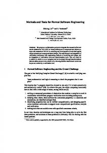
on providing a service or a tool for helping in the real-time analysis of a large number of events from multiple sources. In this case the service that processes data is a Complex Event Processing (CEP) service. Currently, services are being deployed at device level, such in the Internet of Things, which is advocated by the IMC-AESOP project. These services may be considered as data services providing a continuous stream of data. The CEP service may be regarded as an event broker with analytics capabilities and with the ability to connect stack services, making it possible to: 1. Define the flow of events (data) by topics. 2. Define queries (analytics) processing incoming data by topic. 3. Define consumers of events by topics. Implementation Description and Use: To enable the definition of events and topics in an easy way a “CEP Server Launcher Designer” tool has been developed. This tool (see Fig. 6.7) helps to define a list of services that act as sender (e.g. Alarm), consumer (e.g. Dashboard) or broker (e.g. Configuration). The CEP Server is a special instance since it accepts query definitions. Each connection is annotated with the name of the topic. The direction of the arrow (from Alarm to CEP Server) shows the direction of the event flow.
Fig. 6.7 CEP Server Launch Designer
Results: So far the tool has been used internally. Functionally it provides an effective solution, but quantitative results have not yet been collated.
16 This is a preprint version, which may deviate from the final version which can be acquired from https://www.springer.com/gp/book/9783319056234
Harrison et al. 6.3. Prototypes of critical tools, including system modelling and analysis methods
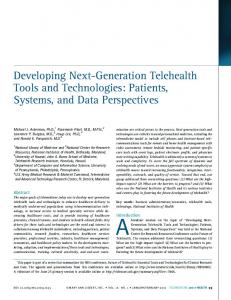
6.3.7 Process Definition Environment, PDE toolkit Requirement: The IMC-AESOP project requires the building and integration of application-related services across a range of systems. The Process Definition Environment (PDE) enables the definition of relationships between system components in support of orchestration or choreography. The PDE toolkit enables systems composed of many logically interlocked components to be visualized and validated.
Fig. 6.8 Process Definition Environment (PDE)
Implementation Description and Use: On the IMC-AESOP project the PDE toolkit was used to validate and visualize Use Cases 1 and 4 for lubrication and building systems, respectively [11]. This is illustrated in Fig. 6.8. Routing logic defined within the PDE toolset enables the material or product flow in the system to be simulated. This in conjunction with a simulation engine enables each application to be observed and validated. The state-based components within the system can be stored in a library with their associated 3D visualisations. The PDE toolkit [12] employs a simulation engine that requires the definition of how the outside world (e.g., product or process parts) interacts with the machinery. This process knowledge, typically defined by a process engineer, is entered into a routing, which in turn drives the input of the sensors in the simulation, which drives the application to react to fulfil the desired logic. Once the control has been validated, it can potentially be downloaded to orchestration engines on a range of SOA devices; however,
17 This is a preprint version, which may deviate from the final version which can be acquired from https://www.springer.com/gp/book/9783319056234
Harrison et al. 6.3. Prototypes of critical tools, including system modelling and analysis methods
this phase was beyond the scope of IMC-AESOP although it is a major objective for future work. The PDE tool supports the deployment of the application logic to orchestrators at potentially any level in the target architecture on a range of target devices. Results: The PDE toolkit has been successfully used to simulate the behaviour of components in the lubrication application of Use Case 1 and verify the behaviour of the district heating system in Use Case 4 as depicted in Chapter 10. Break points have allowed the scenarios defined in these use cases to be quickly evaluated. The inclusion of processes has created the ability to “manage” the automation system using the high-level process view. This results in the control system being easier to understand from a maintenance point of view and in the case of Use Case 4 provides the ability to run different processes based upon external factors, such as long-range weather forecasts.
6.3.8 Continuum Requirement: With the Continuum tool [17] it was possible to create very large control and monitoring structures by using the formal method “High-level Petri Nets” (HLPN). Related to the HLPN theory there are a range of analysis and validation possibilities. The Continuum tool provided a lot of these important functionalities. Based on analysis and validation results, calculated from the tool, it was much easier to introduce the simulation of complex monitoring and control systems in the next step. The start of the implementation of the Continuum tool was in the EU FP6 SOCRADES project where the first control structures were built with this tool. In this project the Continuum tool helped to solve the challenge to design very complex control structures for very large control and monitoring systems in a rapid manner. Implementation Description and Use: The performance challenge was solved by parallelising the algorithms and by using GPUs for the new algorithm design. The company NVIDIA provides a framework called CUDA for parallel programming needs, which was used for the parallelisation. The performance of the Continuum tool is now growing with the increasing performance of NVIDIA GPU technologies. Results: With support from this tool it was possible to generate monitoring and control structures in a very fast way for very large systems. Continuum is a powerful prototype tool with the potential to be extended in the future to a mature engineering tool. First publications are available describing a graphical engineering interface and method that will provide a very easy engineering method. The approach is simple to apply even to very complex control and monitoring structures in a system-ofsystems paradigm, with automatic support for analysis and validation by the tool.
18 This is a preprint version, which may deviate from the final version which can be acquired from https://www.springer.com/gp/book/9783319056234
Harrison et al. 6.4. Engineering Toolkit Application to Use Cases
6.4 Engineering Toolkit Application to Use Cases In order to explain and classify methods and tools employed in the different engineering processes associated with the design, development and commissioning of SOA-based monitoring and control systems on the IMC-AESOP project, architectural levels (e.g. field device, process control system and enterprise management), as defined by the standard ISA-95, have been used. The four use cases introduced in Chapter 1 are presented below, with regard to their functional and architectural aspects, in relation to engineering methods and tools utilized to engineer each of them. The set of tools used in each use case is presented in a diagram, showing the mapping between tools and the addressed ISA-95 architectural levels.
Fig. 6.9 ISA-95 Layers [3]
6.4.1 ISA-95 Layers Applied to the Categorisation of IMC-AESOP Tools A brief description of the ISA-95 standard is included here for completeness. The standard consists of several layers[3]: • ISA-95 Device Level 0-1: ISA-95 device level consists of levels 1 and 0 in the standard. Level 1 is the level for sensing and manipulating the production process, usually consisting of sensors and actuators. Level 1 is connected to Level 0 which is the actual production process, more specifically described as the actual physical process. The device level consists of usually small resource-constrained
19 This is a preprint version, which may deviate from the final version which can be acquired from https://www.springer.com/gp/book/9783319056234
Harrison et al. 6.4. Engineering Toolkit Application to Use Cases
devices that link the service architecture to the production process. The importance of a semantic Web service approach at the device level can be found in [14] • ISA-95 Control/ SCADA Level 2: In general terms this level is concerned with the control and visibility of production processes. This does not include the real time control of processing equipment, which is the concern of Level 1, but chiefly the integration, e.g., the orchestration or choreography of devices, in the Level 1 controllers to achieve specific tasks related to recipes or production objectives. This may be in the form of either orchestration or choreography of devices (e.g., in discrete manufacturing), or supervisory multivariable control of the steady state operation (e.g., in the continuous process industry). • ISA-95 MES Level 3: Manufacturing Execution System (MES) is referred to as Level 3 in the ISA-95 standard. The MES level handles workflow and recipes, among other things, in order to produce the desired products. • ISA-95 ERP Level 4: ISA-95 is a standard developed to address the interface between enterprise and control systems. More specifically, it addresses integration with the production/MES layer as well as B2M transactions. Level 4 as described in ISA-95 deals with business planning and logistics, including plant production scheduling and operational management. The timeframe here could be days, weeks, months or shifts, considerably longer than at the other lower levels. The discussion now moves to focus on the different use-cases and the mapping of tools to these layers.
6.4.2 Use Case 1: Migration of a Legacy Plant Lubrication System to SOA The objective of use case 1 was to demonstrate the migration of an existing lubrication system in an industrial process plant to the IMC-AESOP architecture. Lubrication systems represent one of the most important types of support systems seen in such industries. Although such lubrication systems are critical for good performance, they are often implemented as black-boxes with limited system integration. The tools utilized to engineer the migration of the plant lubrication system to SOA are described below. • C compiler (GCC): A compiler is required to translate the human readable source code into binary code for processors and microcontrollers. The Mulle module uses a Renesas M16C microcontroller. The GNU Compiler Collection consists of a C and several other compilers. GCC supports many different development and target systems. With cross compiling it is possible to develop software on an ordinary PC and compile it to a completely different system e.g. running on an x86 PC. • Timber: Timber is a functional programming language derived from Haskell. Timber is event driven using reactive objects. The compiler compiles from Tim20 This is a preprint version, which may deviate from the final version which can be acquired from https://www.springer.com/gp/book/9783319056234
Harrison et al. 6.4. Engineering Toolkit Application to Use Cases
•
•
•
•
•
•
•
ber to intermediate C code that is parsed to GCC. Other intermediate options like Low Level Virtual Machine (LLVM) are investigated by other organisations. Earlier versions of Timber were interpreted. Flasher: Flasher is a software kit to program flash memories on the Mulle module. Mulle uses a Renesas M16C microcontroller connected to external flash memories. CoAP/EXI: CoAP can support several transfer methods, ranging from human readable XML to more efficient binary methods. In order to enable efficient XML Interchange, EXI has been chosen for this use case due to several performance advantages, such as reduced memory footprint and shorter packets that are more likely to fit in a single (radio) frame. For embedded devices and sensors in particular memory resources are often scarce. Fewer radio frames increase reliability and battery life. SOA4D DPWS Toolkit: One of the major results of recent R&D projects like ITEA2 SIRENA and European FP6 SOCRADES has been a DPWS implementation called SOA for Devices (www.soa4d.org). This implementation has been further improved for the IMC-AESOP approach and used in this use case. Specifically, the SOA4D toolkit is utilized to implement the DPWS support in the service bus, both for the communication with a mediator component and for the communication with a Smart Meter Emulator. Smart Meter Emulator: A simulator for the energy-related aspects of devices targeting smart metering and costs has been developed. It gives the possibility to interact via DPWS and REST with the devices and additionally supports device lifecycle management (e.g., for start/stop/add/remove) of any device, flexible description of classes of devices and their behaviour (done in XML configuration), adjustment of energy prices that are used for operational cost calculation, and support for automated creation of a large number of devices to ease tests (done via XML configuration). TinyOS: TinyOS is designed for low-power wireless devices like Mulle. TinyOS partially supports IPv6 and CoAP. UDP is supported with TCP in prototype form. For CoAP GET & PUT methods are supported, but neither POST nor DELETE are supported. Mozilla Copper plug-in: This plug-in provides a handler for the “CoAP” URI scheme to Mozilla Firefox. With this plug-in capability Firefox can be used for troubleshooting and for some configuration during commissioning. Service Bus Configurator: The Service Bus middleware is intended to run on industrial embedded devices. Such devices typically have very limited HMI capabilities. The Service Bus however needs some means for its configuration and monitoring. This has been achieved through a Web-based application hosted on each device, called a Service Bus Configurator. This application relies on Rich InteLTUrnet Application concepts and has been written using the Google Web Toolkit software development kit. The Configurator application is downloaded from any device hosting the Service Bus into a Web browser running on a computer connected to this device. Communication between the Configurator and the
21 This is a preprint version, which may deviate from the final version which can be acquired from https://www.springer.com/gp/book/9783319056234
Harrison et al. 6.4. Engineering Toolkit Application to Use Cases
Service Bus is based on RESTful Web services. Features that can be configured/monitored using the Service Bus Configurator include: – Adding a new device to the Service Bus (e.g., CoAP edge router and AS-i gateway . . . ) – Monitoring devices/services composing the Service Bus (status, configuration parameters . . . ) – Configuring/monitoring event broker topics and subscriptions – Service Bus system events • WinCC Open Architecture: WinCC-OA [25] is a complex and flexible objectoriented SCADA system that is implemented on the Maintenance station as an HMI solution for the lubrication system. • Step 7: The SIEMENS Step 7 [26] programming environment has been used to investigate the legacy PLC-code in the lubrication system. The result of this analysis was a humanly readable functional description that was then used to implement the SOA-based replacement system functionality that resulted from the migration process. • PDE Toolkit: Provided system application logic simulation, validation and process visualisation. The lubrication system configuration was modelled from its constituent components, e.g., values and pumps, supporting both their state behaviour and 3D schematic visualisation.
Fig. 6.10 Use Case 1 Plant Lubrication Application- Tool mapping into the ISA-95-levels
Fig. 6.10 illustrates how the tools used in Use Case 1 correspond to the ISA-95 levels.
22 This is a preprint version, which may deviate from the final version which can be acquired from https://www.springer.com/gp/book/9783319056234
Harrison et al. 6.4. Engineering Toolkit Application to Use Cases
6.4.3 Use Case 2: Implementing Circulating Oil Lubrication Systems based on the IMC-AESOP Architecture Oil lubrication systems are commonly used in paper machines where hundreds of lubrication points are needed. In general, for the implementation of this use case two different types of tools were used: 1. Development and Deployment tools were used to create, program and configure the necessary behaviours and functions of the use case. 2. Testing tools used to test the developed and deployed system. Development tools used: • Apache ServiceMix: A platform providing useful functionality for integrating technologies internal to components, and WS frameworks for exposing services. • Apache Camel: An open source integration framework based on enterprise integration patterns, which provides connectivity to a wide array of technologies/transports/protocols/APIs, included in ServiceMix. • Jetty: A simple HTTP server, which can be used for consuming and producing HTTP requests. • WS4D-JMEDS (Web services for Devices – Java Multi-Edition DPWS Stack): An open-source stack for developing DPWS clients, devices, and services. • JAX-WS: (Java API for XML Web services) A Java API for developing Web services. • WCF (Windows Communication Foundation): Windows runtime API for developing SOA applications in C#. • StreamInsight:A platform for developing and deploying CEP applications from Microsoft • Ignition Server: A commercial HMI/SCADA system with integrated OPC-UA server. • Ignition Developer API: An application programming interface for developing custom modules for the Ignition Gateway, Designer, or Client in Eclipse. • Eclipse BPEL Designer: A graphical editor for creating BPEL processes. • Orchestration Engine: A tool developed for executing WS-BPEL processes. Testing tools used: • WCFStormLite: For testing WCF Services. • DPWS Explorer: For testing services on DPWS devices. • UA Expert: A free OPC-UA Client for testing OPC-UA and DPWS integration. Fig. 6.11 shows the ISA-95 level for these tools in a graphical form.
23 This is a preprint version, which may deviate from the final version which can be acquired from https://www.springer.com/gp/book/9783319056234
Harrison et al. 6.4. Engineering Toolkit Application to Use Cases
Fig. 6.11 Use Case 2 Circulating Oil Lubrication Application- Tool mapping into the ISA-95levels
6.4.4 Use Case 3: Plant Energy Management The main objective of this use case 3 was to highlight advantages of service orientation, event-driven processing and semantics for easier configuration, dynamic synchronisation and maintenance of complicated multi-layer solutions, which are needed today in continuous process plants. Tools used: • Matlab Simulink: multi-purpose dynamic simulation environment, which was used for development of the power plant dynamic model. • Honeywell UniSim: proprietary simulation environment for development, validation and real-time execution of dynamic process models. • Honeywell Profit Suite: a framework with a set of proprietary tools for development, configuration, and deployment of control applications. • Microsoft StreamInsight: a framework for implementation of Complex Event Processing applications. • Eclipse for JAVA implementation and Microsoft Visual Studio for C++ implementation. • Information model building tools: Address Space Model De-signer (ASMD), XML editor and OPC-UA Model Compiler. tools were used to create the OPCUA address space. This includes nodes, attributes and their mutual relationships. • The data binding tool: for binding of the data items inside a server address space to external data sources. • Information model configuration tool: for the chained Level 2 servers where it allows to create an instance of a sub-system and define device, topology, and binding views. • Electric Vehicle Scheduler/Optimizer: schedules in a optimal way (under constraints) the electric cars of the company. It is implemented as a cloud service (REST) based on SAP HANA Cloud. 24 This is a preprint version, which may deviate from the final version which can be acquired from https://www.springer.com/gp/book/9783319056234
Harrison et al. 6.4. Engineering Toolkit Application to Use Cases
• Orchestrator: used to integrate among the Matlab simulator (via OPC-UA), the Electric Vehicle Scheduler/Optimizer (via REST service calls), and the Energy Market (via REST service calls). • Energy Market: Offers the ability to trade (buy and/or sell) energy on local energy markets as envisioned in the SmartGrid era. It is running as an Internet REST service. Fig. 6.12 illustrates how the tools used to engineering the use case 3 correspond to individual ISA-95 levels.
Fig. 6.12 Use Case 3 Plant Energy Management - Tool mapping into the ISA-95-levels
6.4.5 Use Case 4: Building a System of Systems with SOA Technology – a Smart House Use Case The goal of the District Monitoring use case is to demonstrate the application of the IMC-AESOP architecture in a complex and heterogeneous environment that can enhance the overall comfort and reduce operating costs in residential areas. The application of the IMC-AESOP architecture will allow integration and configuration of operational parameters of various district systems, such as heating, electricity, and transportation. Below is a description of the tools used in the development and implementation of the District Monitoring use case. The tools are categorized in three types: Development and Deployment tools used in the development phase, Core tools that implement the required functionality during the exploitation phase, and Testing tools used to verify the behaviour of the system.
25 This is a preprint version, which may deviate from the final version which can be acquired from https://www.springer.com/gp/book/9783319056234
Harrison et al. 6.4. Engineering Toolkit Application to Use Cases
Tools used: • Integrated Development Environment (IDE): the prototype development used IDEs, such as Eclipse, to assist in the software implementation. This tool was used in all the components of the system in the Development and deployment phase. • Mulle developing kit: This includes a C cross-compiler for Renesas M16C microcontroller (m32c-elf-gcc), a flasher (sflash) to deploy the programs and help libraries available from EISTEC AB. This tool was used for the Mulle components, iRoad/iPark devices and the Car HMI. The C cross-compiler and the flasher are Development and Deployment tools while the help libraries are Core tools. • Contiki: A light-weight OS for IoT devices. This OS provides concur-rent programing and network stack for resource constrained devices. It is a Core tool that is the foundation of the functionality provided by the Mulle and iRoad/iPark components. • Timber compiler and run-time: Used for the real-time CEP simulations in the District management system. It is both Development and Deployment tool and Core tool that execute during the exploitation phase. • CoAP/EXI RESTful engine: An integration of libCoAP or Contiki built-in CoAP implementations and EXIP. It is a Core tool used to provide RESTful Web services in Mulle components, Visualisation console, iRoad/iPark and Car HMI devices. • Mozilla Copper plug-in: It is a web-based interface that is used to test the CoAP interfaces in Mulle components, Visualisation console, iRoad/iPark and Car HMI devices. The tool’s category is Testing. • Complex Event Processing Engine: The CEP engine is based on the Microsoft StreamInsight software for developing CEP applications. This tool is categorized as both a Core and a Development and Deployment tool. • PDE tookit and simulation engine: This component-based engineering environment was used to simulate and visualise the control behaviour of the system. The PDE toolset includes an integrated 3D system visualisation capability and a simulation engine. Once verified the control logic can be deployed to an associated orchestration engine on runtime control systems on a range of platforms. • Continuum: This tool was used in conjunction with the output of the PDE tool to formally analyse different orchestration topologies and verify different system behaviours under varying conditions. Among others, structural and behavioural orchestration specifications can then be validated, e.g., the cyclic and deadlockfree evolution of the system. Fig. 6.13 depicts the tools used in use case 4 and how they correspond to individual ISA-95 levels.
26 This is a preprint version, which may deviate from the final version which can be acquired from https://www.springer.com/gp/book/9783319056234
Harrison et al. 6.5. Conclusions
Fig. 6.13 Use Case 4 Building System of Systems with SOA Technology – a Smart House – Tool mapping into the ISA-95-levels
6.5 Conclusions The methods, tools and practices needed to engineer the next generation SCADA/DCS systems will necessarily vary with the characteristics of the plant and the use cases involved. Nevertheless, on the IMC-AESOP project it has been possible, across the four use cases studied, to extract the common elements to produce an effective IMCAESOP engineering toolkit, to aid anyone wishing to engineer a SOA-based ISA95 multi-layered system solution. Fig. 6.14 summarises the IMC-AESOP tools that could be used to build SOA-based SCADA/DCS applications.
Fig. 6.14 IMC-AESOP Tool mapping into the ISA-95 levels
27 This is a preprint version, which may deviate from the final version which can be acquired from https://www.springer.com/gp/book/9783319056234
Harrison et al. References
Device level support can be provided by CoAP and EXI, using the service bus configurator for integration of devices built using development tools such as Timber and the Mulle development kit, which are deployed on devices running FreeRTOS, TinyOS and Contiki. SCADA functionality can be provided by Ignition and WinCC-OA using the prototype OPC-UA interface for integration with the devices, whilst system modelling, simulation and visualisation is supported by the PDE toolkit for simulation and Continuum for verification. The HANA Cloud is used to provide manufacturing execution system functionality. The enterprise level tools highlighted by IMC-AESOP are the Eclipse BPEL designer and a BPEL orchestrator to execute them. Finally Microsoft’s StreamInsight has been employed for the aggregation and processing of events generated by large scale systems as well as for integration of disparate systems, as part of a system-ofsystems approach. The combined use of these tools allows the engineering of complete applications in which components from any level of the ISA-95 can be integrated to provide a coherent SOA-based SCADA/DCS solution, such as the ones described in Chapters 7-10.
Acknowledgment The authors would like to thank the European Commission for their support, and the partners of the EU FP7 project IMC-AESOP (www.imc-aesop.eu) for the fruitful discussions.
References [1] Ali M, Chandramouli B, Goldstein J, Schindlauer R (2011) The extensibility framework in microsoft streaminsight. In: Data Engineering (ICDE), 2011 IEEE 27th International Conference on, pp 1242–1253, DOI 10.1109/ICDE. 2011.5767878 [2] Andreas T, Saikou D, Charles T (2007) Applying the levels of conceptual interoperability model in support of integratability, interoperability, and composability for system-of-systems engineering. Journal of Systemics, Cybernetics and Informatics [3] Brandl D, Consulting B (2008) What is ISA-95? Industrial Best Practices of Manufacturing Information Technologies with ISA-95 Models [4] Chawla R, Banerjee A (2001) A virtual environment for simulating manufacturing operations in 3D. In: Winter Simulation Conference, pp 991–997, DOI 10.1145/564124.564265, URL http://dblp.uni-trier.de/db/conf/wsc/wsc2001. html#ChawlaB01
28 This is a preprint version, which may deviate from the final version which can be acquired from https://www.springer.com/gp/book/9783319056234
Harrison et al. References
[5] CommSrv (2013) Address space model designer. URL http://www.commsvr. com/Products/OPCUA/UAModelDesigner.aspx [6] Dai W, Vyatkin V (2010) Redesign distributed iec 61131-3 plc system in iec 61499 function blocks. In: Emerging Technologies and Factory Automation (ETFA), 2010 IEEE Conference on, pp 1–8, DOI 10.1109/ETFA.2010. 5641239 [7] IEC (2009) Function Field device tool (FDT) interface specification, IEC 62453. Tech. rep., Geneve [8] IEC (2010) Function blocks (FB) for process control – Part 3: Electronic Device Description Language (EDDL), IEC 61084-3 Ed. 2.0. Tech. rep., Geneve [9] Ignition (2013) Inductive Automation, Ignition Server. URL http://www. inductiveautomation.com/scada-software [10] Karnouskos S, Goncalves Da Silva P, Ilic D (2012) Energy Services for the Smart Grid City [11] Kaur N, Harrison R, West A, Phaithoonbuathong P (2010) Web ServicesBased Control Devices for Future Generation Distributed Automation Systems. In: Proceedings of the World Congress on Engineering (WCE), London, UK, vol 3 [12] Kaur N, McLeod C, Jain A, Harrison R, Ahmad B, Colombo A, Delsing J (2013) Design and simulation of a soa-based system of systems for automation in the residential sector. In: Industrial Technology (ICIT), 2013 IEEE International Conference on, pp 1976–1981, DOI 10.1109/ICIT.2013.6505981 [13] Li C, Qi J, Shu H (2008) A SOA-Based ARIS Model for BPR. In: e-Business Engineering, 2008. ICEBE ’08. IEEE International Conference on, pp 590– 595, DOI 10.1109/ICEBE.2008.14 [14] Lobov A, Lopez FU, Herrera VV, Puttonen J, Lastra J (2009) Semantic Web Services framework for manufacturing industries. In: 2008 IEEE International Conference on Robotics and Biomimetics, IEEE, pp 2104–2108 [15] Maier M (2005) Research challenges for systems-of-systems. In: Systems, Man and Cybernetics, 2005 IEEE International Conference on, vol 4, pp 3149– 3154, DOI 10.1109/ICSMC.2005.1571630 [16] Maier MW (1998) Architecting principles for systems-of-systems. Systems Engineering, John Wiley & Sons, Inc 1(4):267–284 [17] Mendes J, Bepperling A, Pinto J, Leitao P, Restivo F, Colombo A (2009) Software methodologies for the engineering of service-oriented industrial automation: The continuum project. In: Computer Software and Applications Conference, 2009. COMPSAC ’09. 33rd Annual IEEE International, vol 1, pp 452– 459, DOI 10.1109/COMPSAC.2009.66 [18] Microsoft (2013) Microsoft streaminsight. URL http://technet.microsoft.com/ en-us/library/ee362541.aspx [19] Minor J (2011) Bridging OPC-UA and DPWS for Industrial SOA. Master’s thesis, Tampere University of Technology, URL http://dspace.cc.tut.fi/dpub/ bitstream/handle/123456789/20954/minor.pdf
29 This is a preprint version, which may deviate from the final version which can be acquired from https://www.springer.com/gp/book/9783319056234
Harrison et al. References
[20] OASIS (2013) OASIS Web Services Business Process Execution Language (WSBPEL) TC. URL https://www.oasis-open.org/committees/tc_home.php? wg_abbrev=wsbpel [21] Riedl M (2005) Distributed object model environment. PhD thesis, Otto-vonGuericke-Universität Magdeburg [22] Riedl M, Naumann F (2011) EDDL: Electronic Device Description Language. Oldenbourg Industrie verlag [23] SAP (2013) SAP HANA Cloud. URL http://www.sap.com/pc/tech/inmemory-computing-hana/software/overview/index.html [24] SAP (2013) Sap manufacturing and intelligence (mii). URL http://www.sap. com/solution/lob/manufacturing/software/integration-and-intelligence/ [25] SIEMENS (2013) SCADA System SIMATIC WinCC Open Architecture. URL http://www.automation.siemens.com/mcms/human-machine-interface/ en/visualization-software/simatic-wincc-open-architecture/ [26] SIEMENS (2013) SIEMENS SIMATIC STEP 7. URL http://www. automation.siemens.com/mcms/simatic-controller-software/en/step7/
30 This is a preprint version, which may deviate from the final version which can be acquired from https://www.springer.com/gp/book/9783319056234