GUMASTE LAYOUT
2/16/05
10:57 AM
Page 72
OPTICAL STORAGE AREA NETWORKS
Next-Generation Optical Storage Area Networks: The Light-Trails Approach Ashwin Gumaste and Si Qing Zheng, The University of Texas at Dallas
ABSTRACT Multiple architectures, technologies, and standards have been proposed for storage area networks, typically in the WAN environment. The transport aspect of storage signifies that optical communications is the key underlying technology. The contemporary SAN over optical network concept uses the optical layer for pure transport with minimal intelligence. This leads to high cost and overprovisioning. Future optical networks, however, can be expected to play a role in optimizing SAN extension into the WAN. An essential characteristic of SAN systems is tight coupling between nodes in a SAN network. Nodes in a SAN system have two critical functions that are presently emulated by data layers and can be offloaded to the optical layer. First, nodes need to signal among each other to achieve tasks such as synchronous and asynchronous storage. Second, to benefit from an optimized network, nodes need to allocate bandwidth dynamically in real time. In this article we show how the optical layer can be furthered from just pure transport to creating opportunities in provisioning as well as providing the mirroring function of SAN systems (multicasting) and consequently lead to reduction in cost. We demonstrate that the light-trail model is one way of efficiently utilizing the optical layer for SAN.
INTRODUCTION The vast explosion of data traffic and the growing dependence of the financial world on electronic services have led to a tremendous incentive for storage area network (SAN) services and storage-capable networks. Coupled with a need to store information and dynamically reproduce it in real time, SANs are experiencing a new upward thrust. Local SANs based on the intra-office client-server hub-and-spoke model have long been deployed as the de facto standard for backing up servers and high-end computing devices within campuses and premises. However, with the growth of the Internet, back office operations, and a need for secure backup at geographically diverse locations, SANs have moved from their premises confinement to a larger area of proliferation. These new categories of SAN sites, also known as Internet data centers (IDCs), are becoming increasingly impor-
72
0163-6804/05/$20.00 © 2005 IEEE
tant from the revenue as well as security perspectives. These sites are connected to one another and to their client nodes through a transport medium. Considering the high volume of data that is transferred between clients and servers today, transport is likely to take place across optical communication links. Optical fiber offers large bandwidth for high-volume transfer with good reliability to facilitate synchronous backup capabilities between SAN sites and clients or between multiple SAN sites in server mirroring operations. Currently, optical channels are used only for transport of information, while standardized protocols such as Fibre Channel, ESCON, and FICON operate at the data layer, enabling actual transfer of information. With the sharp rise in the need for dynamic services, future SAN systems should be able to cater to dynamic provisioning of “connections” between server sites and clients. Bandwidth provisioning in a low-cost setup is the key challenge for future SAN systems. The most natural way to facilitate these services is to enable a protocol residing hierarchically over the data layers, facilitating the necessary dynamism in bandwidth arbitration as well as guaranteeing quality of service (QoS) at the optical layer. This, however, complicates the process and leads to expensive solutions as nodes then would have to perform hierarchical protocol dissemination. The optical layer that has so far been used primarily just for transport can, however, be pushed further to satisfy some of the cutting-edge needs of next-generation SAN systems. These include multicasting for multisite mirroring, dynamic provisioning for low-cost asynchronous by timely backup, and providing a low-cost system that takes advantage of the reliability and resiliency of the optical layer. We propose the concept of light-trails [1–4] as a solution for optical SANs to meet the aforementioned challenges and provide a path to future wide area SAN systems or SAN extensions. We subsequently show how the light-trail solution is adapted for SAN extension in the WAN by harping on the properties of dynamism, multicasting, and low deployment costs. This article is organized as follows. We describe the light-trails solution and discuss light-trails for SAN extension. We describe lighttrails for disaster recovery, and then outline the relationship between SAN extension and computational grids through light-trails. We position
IEEE Communications Magazine • March 2005
GUMASTE LAYOUT
2/16/05
10:57 AM
Page 73
Lightpath: new wavelength for each connection
Drop and continue with passive adding section Node architecture
Unicasting and multicasting using light-trails: creating sub-lambda communication over a single wavelength
Multiplex section
Demultiplex section
The drop-andcontinue feature allows nodes to communicate to one another through time non-overlapping
Convener node
End node
Optical combiner or splitter coupler Optical on/off switch
n Figure 1. The conceptual differences between a lightpath and a light-trail, and the architecture of a lighttrail node.
connections without optical switching. The switch-less aspect makes a light-trail analogous
light-trails with respect to contemporary SAN extension solutions and then summarize the article.
THE LIGHT-TRAILS SOLUTION A light-trail is a generalization of a lightpath (optical circuit) in which data can be inserted or removed at any node along the path. Light-trails are a group of linearly connected nodes capable of achieving dynamic provisioning in an optical path through an out-of-band control channel (overlaid protocol). This leads to multiple source-destination pairs able to establish time differentiated connections over the path while eliminating the need for high-speed switching. A light-trail is characterized by a segment of nodes that facilitate unidirectional communication. A node in a light-trail employs the drop-and-continue feature, which allows nodes to communicate to one another through non-timeoverlapping connections without optical switching. The switchless aspect makes a light-trail analogous to an optical bus. However, a lighttrail, due to its out-of-band protocol, enhances the known properties of an optical bus. The methods for implementing optical networks of both ring and mesh topologies using light-trails are presented in [1–3, 5]. Shown in Fig. 1 are the conceptual differences between a lightpath and a light-trail. The first node in a light-trail is called the convener node, while the last node is called the end node. The light-trial, which essentially resides on a wavelength, is optically switched between these two nodes. Multiple light-trails can use the same wavelength as long as the wavelengths do not overlap, thereby leading to spatial reuse of the wavelength. Light-trails present a suitable solution for traffic grooming. It was shown in [6, 7] that multiple nodes can share an opened wavelength in an optimum way to maximize the wavelength’s utilization. The control channel has two primary functions: • Creation and deletion of light-trails (macromanagement) • Creation and deletion of connections within light-trails (micromanagement) The macromanagement function of the control channel is responsible for setting up, tearing down, and dimensioning of light-trails. Dimen-
IEEE Communications Magazine • March 2005
sioning of light-trails means growing or shrinking light-trails in order to meet the requirements of a virtual embedded topology. Macromanagement involves switching of a wavelength at the convener and end nodes in order to create the optical bus. Macromanagement is a simple procedure but somewhat static in time and thus seldom used. Micromanagement, on the other hand, is more dynamic. It is invoked whenever two nodes communicate with one another using an existing or preset light-trail. Hence. this procedure does not require switching. Through micromanagement, connections can be set up/torn down or QoS needs met as desired purely using software control. The overlaid control layer actively supports both forms of light-trail management. Nodes arbitrate bandwidth through the control layer. In this article a scheme for bandwidth arbitration for SAN nodes using lighttrails at the optical layer is also discussed. Since at a given time only one connection can reside in the light-trail, the chosen connection must meet requirements of fairness by allowing other nodes to take part in a timely and fair manner. What makes light-trails unique for SANs is their ability to meet the emerging demands of SANs, such as optical multicasting and dynamic provisioning, while maintaining low implementation cost. Besides, the light-trail solution provides an opportunistic mechanism that couples the data and optical layers through a control scheme. This control scheme can be implemented in several ways; two such implementations are discussed in [5, 8]. It is the control software that couples the two layers together, but this cannot happen without a hardware that allows itself to be configured. The combination of the light-trails solution — hardware and software — creates a dynamically provisionable network. This combination potentially solves the uncertainty equilibrium between switching and transport layers by optimized provisioning (provides bandwidth whenever needed). If we compare the light-trail solution to a solution consisting of wavelength-division multiplexing (WDM) adddrop multiplexers and overlaid control, the latter is unable to provide the necessary dynamism or optical multicasting. The obvious hindrance would be inline optical switching, which is somewhat slow (microelectromechanical system, MEMS, being the most prolific in today’s service provider networks), and suffers from impair-
to an optical bus. However, a lighttrail due to its outof-band protocol enhances the known properties of an optical bus.
73
GUMASTE LAYOUT
2/16/05
SAN protocols like
10:57 AM
Page 74
Client
Server
Client
Server
Server
Fibre Channel were designed without considering the present advances in optical technology. However, Fibre Channel can be
Sink
Source
Sink
Source
Sink
tailored to suit light-trails very easily, and this tailoring has great benefit in terms of both technological advances as well as cost reduction.
A1
A2
A3
Burst mode transmitter
Middleware + light-trail control
Burst mode receiver
Fibre Channel buffer
An-1
An
Light-trail
Extra buffer (mirror)
n Figure 2. Unidirectional implementation of light-trail with middleware to facilitate Fibre Channel into a dynamic provisonable medium.
ments such as crosstalk and extinction ratio. Besides the switching, another hindrance in conventional schemes is the requirement of signaling. However, this is cleanly and clearly defined in light-trails [1, 3]. The light-trail node architecture removes these obstacles by deploying the drop-and-continue methodology. It then provides for the ability to provision connections (micromanagement) using pure software (signaling) methods, eliminating optical switching altogether from micromanagement of light-trails. The light-trail system presents itself as an opportunistic medium for nodes that reside on a trail. Such a system allows nodes to pitch in their data without switching whenever possible in the best possible trail. The dynamic nature of communication within a light-trail indicates a need for optical components such as lasers and detectors that can be switched on and off dynamically. While these burst mode technologies have reasonably matured [9], the light-trail system (along with passive optical network, PON) effectively uses such technologies. Burst mode transmitters and receivers that enable dynamic communication carry out the function of micromanagement in light-trails, setting up and tearing down connections as desired. The maturity of these technologies, shown by their prominence in consumer-centric markets like PON, also means that there is not much of a cost difference from conventional continuous wave (CW) lasers and detectors. Reference [2] gives the reader a more detailed explanation of light-trail optical performance as well as an in-depth analysis of the associated technologies and costs.
LIGHT-TRAILS FOR SAN EXTENSION In this section we consider light-trails for SAN extension. SAN protocols like Fibre Channel were designed without considering the present advances in optical technology like the dropand-continue architecture manifested in lighttrail nodes as well as dynamic reconfigurable fabrics. However, Fibre Channel can be tailored
74
A4
to suit light-trails very easily, and this tailoring has great benefits in terms of both technological advances as well as cost reduction. First we will consider how light-trails can provide technological benefits with characteristics such as dynamic provisioning, and then show how to maximize the efficiency of Fibre Channel through optical multicasting. Finally, we include a brief discussion on cost reduction through light-trails. An n-node light-trail can in principle support nC source-destination pairs, as long as only one 2 source is transmitting at any given time (there may be multiple destinations though). In contrast, for real-time backup operations as in Fibre Channel it is required that several nodes communicate somewhat simultaneously through, say, a preset light-trail. To meet this requirement we propose a simple modification that allows multiple nodes to communicate on a real-time basis through a set of bandwidth arbitration algorithms for Fibre Channel tailored to meet lighttrail specifications. For these algorithms to function, we make good use of the buffers within Fibre Channel interfaces. The implementation of this scheme is shown in Fig. 2, in which we show only one direction of communication; the reverse is exactly the opposite. Let us assume a middleware that interacts between the Fibre Channel interfaces (with control) and the light-trail management system (micro and macro). The middleware then runs an algorithm that allows only one Fibre Channel transmit interface to communicate through a light-trial at a given time. The middleware also interacts with the optical devices (burst mode transmitters and receivers) to enable this sporadic on-off communication. The middleware can be implemented through generic distributed processing algorithms or more prolific bandwidth auctioning algorithms. The optimal bandwidth assignment strategy is an area of ongoing research and can lead to various implementations, so it is left as an open issue. The middleware has the task of scheduling as well as aggregating connections. The middleware thus aggregates data elec-
IEEE Communications Magazine • March 2005
GUMASTE LAYOUT
2/16/05
10:57 AM
Page 75
1
1.00E+07
0.1 1.00E+05
1.00E+04
Delay (s)
Provisioning time of a connector
1.00E+06
1.00E+03
0.01
Allowable latency Light-trail queuing delay Static lightpath queuing delay
1.00E+02 0.001 WDM dynamic channel provisioning Light-trail connection provisioning
1.00E+01
0.0001
1.00E+00 10
20
30
40
50
60
70
80
90
100
10
30
50
70
Load in percentage
Load in percentage
(a)
(b)
90
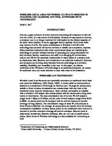
n Figure 3. Performance metric of a light-trail for SAN extension compared to conventional WDM for SAN extension: a) provisioning time; b) delay. Note the trade-off between connection queuing delay and provisioning time.
tronically in the Fibre Channel interface buffers and allocates bandwidth at appropriate times. Consider an n-node light-trail A1, …, An such as that shown in Fig. 2. It is assumed that each node is connected to a SAN interface like Fibre Channel. For the sake of simplicity let us also assume that k of these n nodes are client nodes (sources), and the remaining k – n nodes are servers (primarily sinks) that store the data somewhat in real time (synchronously). Data that arrives at the k SAN client interfaces from their client network is buffered in the Fibre Channel interface buffers that are typically 8–256 Mb, and are used to store the data until an acknowledgment of successful transport of this data is received. In addition, to suit the dynamic provisioning of the light-trail system, we make a small deviation from the generic Fibre Channel specification, allocating exactly one more buffer (of the same size as used by the Fibre Channel interface) at each client node site (Fig. 2). This extra buffer is collocated with and the mirror of the original buffer. The critical aspect of this network then is to optimally use the opened single wavelength (light-trail) to ensure communication among n nodes unidirectionally (to complete duplex we need another light-trail, not shown in Fig. 2 to preserve clarity). This is done as follows. The middleware interacts with both optical layer as well as Fibre Channel interfaces. It allocates bandwidth to a connection based on a threshold policy. The threshold policy can be adapted from one of the many known distributed fairness mechanisms like that of auction theory whereby the allocated bandwidth (time interval for transmission) is proportional to the criticality of the transmitting node as well as the criticality of the node’s peers in the light-trail. This means that a node would get transmitting rights to the channel when its buffers reach a criticality level at which they must be emptied. However, the amount they are
IEEE Communications Magazine • March 2005
emptied depends on the buffer occupancies of all other nodes in the same light-trail (fairness). Since the middleware is by itself a fast real-time computational algorithm (e.g., a gaming schemeor threshold policy algorithm), wavelength utilization can be maximized; almost 95 percent utilization is demonstrated in [2]. The drawback is the slight queuing delay experienced by Fibre Channel interfaces. For the acknowledgment-based Fibre Channel, the first buffer is used to store the data being transmitted, while the second buffer is used to collect data for future transmission. To evaluate this scheme we constructed a simulation to examine the benefits of statistical multiplexing of the connections regarding the expected queuing delay. The simulation model used consists of a 16-node ring network with 40 wavelengths. Fibre Channel traffic arrival is Poisson, and connections are queued up from frames at Fibre Channel interfaces in 64 Mb buffers. Light-trail size is mean of 8 nodes with a variance of 6. The line rate is 2 Gb/s FC. Shown in Fig 3a and 3b are the performance metrics of provisioning and queuing for light-trails compared to WDM lightpath solutions. Here load is calculated through a normalization process of actual load on maximum possible allowable load. It is seen that light-trails offer excellent provisioning but suffer in queuing delay. However, the trade-off is acceptable because the queuing delay is less than the maximum permissible end-to-end delay (shown in Fig. 3b).
LIGHT-TRAILS FOR DISASTER RECOVERY One of the key benefits that light-trails offer to SAN-extension is their ability to dynamically provision the optical layer, which has been shown previously. In this section we show how this abstract benefit can yield an impact on SAN
75
GUMASTE LAYOUT
2/16/05
10:57 AM
Page 76
a) Data center
A B
E D
C
b) Data center
Light-trail node
A
B
E D
C
Server
c) Data center
Light-trail node
A B
E DC
C Light-trail node
Server
Light-trail used to recover Back up path from server data to hub
n Figure 4. Disaster recovery implementations for SAN using Fibre Channel over WDM and SAN using light-trails. Note the apparent fewer number of wavelengths required in the light-trail case.
76
extension technologies pertaining to disaster recovery by considering the application of business continuance through a simple example, and compare the light-trials solution to a generic WDM solution involving lightpaths. Shown in Fig. 4a is a SAN extension over a WDM Fibre Channel network; Fig. 4b shows a corresponding light-trail implementation. The networks chosen here are physical (optical) ring topologies with a logical hub-and-spoke model. The physical ring can be extended to a physical mesh if needed [2]. We assume multiple spoke nodes on the periphery of the ring logically connected to a single hub node (data center). Storage servers reside at spoke nodes as well as the hub node. The storage servers at the spokes mirror their data to the server at the hub node. The data center at the hub node is a high-performance high-availability SAN element with both reliability and availability significantly better than the servers at the spokes. This system showcases typical disaster recovery scenarios for financial institutions and large enterprises, which have both local storage (at the periphery) as well as geographically diverse central storage. In the ring networks shown in Fig. 4 we assume that each optical node on the ring is connected locally on the client side to a server, and on the network side to the optical ring. The local server is connected to enterprises or SAN application clusters. For business continuance the server is synchronously backed up using circuit-type connections or lightpaths over which a SAN protocol like Fibre Channel ensures communication. In Fig. 4a it is shown that WDM add-drop elements readily support this synchronous backup arrangement by provisioning lightpaths. Lighttrails too readily support these lightpaths or optical circuits, but they result in a significant cost saving as shown in Fig. 4b. The cost saving comes from the fact that the WDM solution cannot support multiple destinations on the same wavelength, while the light-trail can. This leads to transponder savings and hence cost benefits. To understand the benefit of light-trails for business continuance, let us define two operation modes for the network: normal and failure. For light-trails in the normal mode, each server (node) communicates with the business continuance data center (hub) using a static wavelength circuit or lightpath backing up its data in real time. This means the light-trail provisioned here is used for point-to-point connection between a fixed source and a fixed destination. Using this upstream light-trail (from spoke to hub), the spoke node backs up its data into the hub in real time. The business continuance data center at the hub then acknowledges receipt of all data blocks from all the spokes via a single downstream light-trail that has all the spokes as prospective destinations. The servers connected to this light-trail at the spokes can electronically select or discard frames based on the Fibre Channel destination tag. This system works well assuming an asymmetric traffic ratio, that is, the ratio of traffic from the servers to the data center far exceeds that from the data center to the servers; this is the case for such applications. However, in failure mode the situation differs significantly. Assume that a server at a spoke
IEEE Communications Magazine • March 2005
2/16/05
10:57 AM
Page 77
crashes, thus losing its data; hence, the clusters of enterprises or workstations connected to this server have a need for immediate restoration of services (data) in order to ensure business continuance. The downstream light-trial, used so far only for sending acknowledgment control messages (from hub to spokes) then becomes the de facto backup medium. The light-trial, which is accessible to every spoke node and in normal mode only carries acknowledgment (negligible) traffic now can carry the backup traffic as well. During this continuance operation in failure mode, the hub node sends Fibre Channel frames through this light-trail to all the spokes. Only the spoke for which the Fibre Channel frame is destined accepts the frame, while all other spokes simply discard a nonmatched frame. In the recovery phase, the server that is recovering all its crashed data acknowledges to the data center through the original circuit it used for backing up to the hub; this is shown in Fig. 4c. This way business continuance occurs while simultaneously conserving the need for extra transponders. Shown in Fig. 5 is a comparison of the cost of transponders required in a generic WDM SAN extension network and that in the network with light-trails. There is a direct benefit of (N – 2) transponders through deployment of light-trails. Furthermore, savings in transponders is prolific because of their high cost due to the high-speed electronics and wavelength-sensitive optics involved. Apart from the cost savings there is another significant benefit: availability of a wavelength. In a generic WDM network for SAN extension, the backup path from the data center to the failed server node has to be dynamically provisioned. The time required for dynamic provisioning of the backup path is proportional to signaling and switching of the path. However, as can be seen in Fig. 4c, the backup path on the downstream light-trail is preprovisioned for any node failure, thus eliminating switching time altogether.
GRID COMPUTING AND STORAGE AREA NETWORKS: THE LIGHT-TRAILS CONNECTION Computational grids [10] are growing as an emerging phenomenon, bridging the gap between communication and computing with a view to creating enormous processing power in economically viable setups. Grid computing enables applications with high processing requirements over distributed networks. The light-trail hierarchy manifests itself as an opportunistic solution for grid computing by providing a medium for distributed processing as well as lowering the memory-processor access time through the grid. Consider an enterprise grid system where clusters of computers (nodes) are interconnected through an optical WDM backbone. The traffic pattern varies dynamically and hence needs dynamic setup and teardown of connections. The light-trail system with its ability to provide dynamic connections without switching can then be a natural candidate for grid applications. Since this article focuses on light-trails for SAN and not for grids, we focus on an aspect of SAN
IEEE Communications Magazine • March 2005
3000
WDM SAN Light-trail-based SAN
2500
Transponder cost i($1000s)
GUMASTE LAYOUT
2000
1500
1000
500
0 5
7
9
11
13
15
Network size (number of nodes)
n Figure 5. Transponders cost comparison of SAN using Fibre Channel over WDM (left) and SAN using light-trails.
that needs to be considered for computational grids and light-trails can facilitate successfully. The computational grid uses resources such as processors from multiple nodes. However, a grid in order to function also requires storage locations that serve as points of information source as well as record grid activity and maintain grid databases. To meet the storage aspect, a grid must necessarily be connected to storage servers (multiple servers for redundancy and to maintain distributed property). The traffic between these central locations and nodes is extremely dynamic, exemplifying the interactions between processors and memories. If we implement a WDM switch-based system (dynamic lightpath or burst switching), the system would not be able to meet requirements for provisioning the dynamism in traffic, or simply be overprovisioned and hence expensive. However, the optical bus property of a light-trail readily meets these dynamic traffic demands at a small tradeoff: no wavelength reuse (within the light-trail) and some queuing delay. Shown in Fig. 6 is a computational grid extended through a light-trail system. The processors are connected to clusters at each node site, while the memory aspect is provided by SAN servers. It is assumed that a pair of opposite light-trails are bound between two SAN servers. The two SAN servers connect to each other by port mirroring through these two light-trails. Let us examine how this system functions: when two grid nodes communicate to one another the SAN servers located at the end of each light-trail “listen” to this ongoing traffic. The servers can then be adapted to selectively accept the storage content of the traffic and discard other trivial interactions. Occasionally the two extreme SAN servers exchange their infor-
77
GUMASTE LAYOUT
2/16/05
10:57 AM
Page 78
Grid clusters
The light-trails concept is the ideal implementation method for SAN extension over grid computing, because it provides for two key functions of dynamic bandwidth allocation as well as optical multicasting. The latter is the key to being able to hear all the traffic between node pairs. Middleware
SAN server
Light-trails on different wavelengths (colors) exemplifying a virtual embedded topology
Optical transponder shelf based on burst mode technology
n Figure 6. Grid computing and SAN — the light-trail connection. mation (using the same light-trail). This allows both servers to maintain an exact copy of the data to be stored as well as provide geographically diverse redundancy. If an enterprise creates a SAN extension as part of the grid network, grid transactions would be backed up synchronously, as mentioned above, thus providing stability to the grid nodes. In such a case the SAN extension is able to “hear” all the traffic that goes through between grid nodes, and decipher which traffic to select and save and which to discard. When a node on the grid crashes, the SAN extension is able to dynamically allocate bandwidth to this node using a preset light-trail and thereby get the node to pull back all its lost data. In addition, if the crashed node has to be replaced with some other node, again bandwidth can dynamically be provisioned to this new node. The light-trails concept is the ideal implementation method for SAN extension over grid computing, because it provides for two key functions of dynamic bandwidth allocation as well as optical multicasting. The latter is the key to being able to hear all the traffic between node pairs.
POSITIONING A LIGHT-TRAIL SOLUTION FOR CONTEMPORARY SAN EXTENSION The optical layer, so far used primarily for just transport, can, through light-trails, be pushed further to meet some of the cutting-edge needs of next-generation SAN systems, such as multicasting for multisite mirroring and dynamic provisioning for low-cost asynchronous but timely backup. Light-trials can be used to construct a low-cost SAN system taking advantage of the reliability and resiliency of the optical layer. Shown in Fig. 7 is a summary of the advantage
78
of light-trails for SAN systems compared to contemporary networks. In Fig. 7a we show the implementation of a SAN on a WDM optical layer. We show the dynamism exemplified by the network (ability to set up and tear down connections) through the solid line and the cost of the solution through the dashed line as functions of network sizes. It is obvious that the network is not able to facilitate enough dynamism like that generated by IP type interfaces. Shown in Fig. 7b is the performance of a control hierarchy that logically controls SAN interfaces as well as produces a dynamic network. This hierarchy is implemented through an IP+multiprotocol label switching (MPLS) layer over an optical layer. We choose IP because of its dominance as the protocol of choice in worldwide networks. The IP+MPLS network has tremendous dynamism in terms of bandwidth provisioning, but the cost of such a network is also extremely high, as shown by the dashed line. The cost is due to IPlayer processing, which is significantly expensive at higher bit rates. Finally, in Fig. 7c we show the performance of light-trails for SAN extension. We see the benefits in terms of both dynamism and cost. The light-trail’s out-of-band control scheme bridges the data and optical layer together without actually going one layer above the SAN layer. It is this bridging of the layers that creates the opportunistic framework of light-trails, one that solves the uncertainty between switching and transport layers, and leads to better performance and lower cost.
SUMMARY SAN has emerged as a de facto requirement in enterprise and mission-critical networks in order to ensure business continuance and real-time backup. The SAN is extended into the WAN to meet requirements such as maintaining geo-
IEEE Communications Magazine • March 2005
GUMASTE LAYOUT
2/16/05
10:57 AM
Page 79
SAN (IP+MPLS) control Cost Dynamism
SAN protocols Optical transport Size of network (a)
Cost Dynamism
SAN protocols Optical transport Size of network (b)
The ability to provide critical functions such as dynamic provisioning and optical multicasting, while yet being cost-effective and pragmatic to deploy, makes light-trail an
Cost Dynamism
SAN protocols
Light-trail control
Light-trail optical transport
attractive candidate Dynamism in connections Cost of solution
for SAN extension.
Size of network (c)
n Figure 7. Comparing light-trails for SAN extension from bandwidth provisioning and cost perspectives
with a conventional optical transport solution as well as a hierarchical IP+MPLS solution to facilitate the necessary dynamism in bandwidth allocation: a) SAN over WDM; b) SAN + MPLS over WDM; c) SAN over light-trails.
graphic diversity and creating central secure information banks. Optical networks are natural candidates for enabling SAN extension into the WAN. However, today’s optical networks offer little apart from pure transport function to the overlaid SAN. If the optical layer can facilitate emerging requirements of the SAN extension by providing the necessary intelligence, then the converged network would lead to betterment of price and performance. To facilitate intelligence in the optical layer and meet the growing demands of SAN extension, we propose the concept of light-trails to facilitate SAN extension over optical networks. The ability to provide critical functions such as dynamic provisioning and optical multicasting, and still be cost-effective and pragmatic to deploy, makes light-trails an attractive candidate for SAN extension. We show in this article the performance of lighttrails for SAN extension in multiple scenarios like disaster recovery, dynamic sharing of a wavelength, and applications in grid computing.
REFERENCES [1] A. Gumaste, “Light-Trails and Light-Frame Architectures for Optical Networks,” Ph.D. thesis, Fall 2003, UT-Dallas; at: www.cotrion.com/light-trails [2] A. Gumaste and I. Chlamtac, “Mesh Implementations of Light-Trails: A Solution to IP Centric Communication in the Optical Domain,” 12th Proc. IEEE Intl. Conf. Comp. Commun. Networks, Dallas TX, 2003. [3] A. Gumaste and I. Chlamtac, “Light-Trails: An Optical Solution for IP Transport ,” J. Opt. Net., vol. 3, 2004; http://www.osa-jon.org/abstract.cfm?URI=JON-3-5-261, pp. 261–81. [4] A. Gumaste and S. Q. Zheng, “Protection and Restoration Mechanisms in WDM Ring Light-trail Networks,” 9th Opt. Network Design and Modeling Conf., Milan, Italy, Feb. 2005. [5] A. Gumaste and I. Chlamtac, “GMPLS Adaptations to Providing End to End QoS: The Light-Trails Approach,” NFOEC 2003, Orlando, FL.
IEEE Communications Magazine • March 2005
[6] A. Gumaste, G. Kuper, and I. Chlamtac, “ Optimizing Light-Trail Assignment for IP Centric Communication,” Proc. 13th IEEE LANMAN, San Francisco, CAApr. 2004. [7] M. Frederick, N. VanderHorn and A. Somani, “Light Trails: A Sub-Wavelength Solution for Optical Networking,” Proc. IEEE HPSR 2004, Phoenix Arizona. [8] M. Yoo and C. Qiao, “Just-Enough-Time (JET): A High Speed Protocol for Bursty Traffic in Optical Networks,” Proc. IEE/LEOS Tech. GII, Aug. 1997, pp. 26–27. [9] Y. Ota et al., “High-Speed, Burst-Mode, Packet-Capable Optical Receiver and Instantaneous Clock Recovery for Optical bus Operation,” J. Lightwave Tech., vol.12, no.2, Feb. 1994. [10] I. Foster and C. Kesselman, The Grid: Blue Print for a New Computing Infrastructure, Morgan Kauffman, Nov. 1998.
ADDITIONAL READING [1] A. Gumaste and S. Q. Zheng, “Optical Implementation of RPR Using Light-Trails,” to appear, Proc. OFC/NFOEC, 2005.
BIOGRAPHIES ASHWIN GUMASTE (
[email protected]) received a Ph.D. from the University of Texas at Dallas and is currently with Fujitsu Laboratories of America as a member of research staff in the Photonics Networking Laboratory. He previously worked in Fujitsu Network Communications R&D and prior to that with Cisco Systems in the Optical Networking Group. He has written numerous papers and has over 30 pending U.S. patents, and in 1991 he was awarded the National Talent Search Scholarship in India. He has authored three books on broadband networks: DWDM Network Designs and Engineering Solutions, First Mile Access Networks and Enabling Technologies (both, Pearson Education), and Broadband Services: User Needs, Business Models and Technologies (Wiley). SI QING ZHENG received a Ph.D. degree from the University of California, Santa Barbara, in 1987. Currently, he is a professor of computer science, computer engineering, and telecommunications engineering at the University of Texas at Dallas. His research interests include algorithms, computer architectures, networks, parallel and distributed processing, telecommunications, and VLSI. He has published 200 papers in these areas.
79