The NASA STI Program operates under the auspices of the Agency ..... Vacuum.
Cham ber x 6. Figure 8.—Block diagram of heater test setup. The heater test will ...
https://ntrs.nasa.gov/search.jsp?R=20080006654 2017-09-16T16:45:38+00:00Z
NASA/TM—2007-215036
AIAA–2007–5276
NEXT Thruster Component Verification Testing Luis R. Pinero Glenn Research Center, Cleveland, Ohio James S. Sovey Alphaport Incorporated, Cleveland, Ohio
December 2007
NASA STI Program . . . in Profile
Since its founding, NASA has been dedicated to the advancement of aeronautics and space science. The NASA Scientific and Technical Information (STI) program plays a key part in helping NASA maintain this important role. The NASA STI Program operates under the auspices of the Agency Chief Information Officer. It collects, organizes, provides for archiving, and disseminates NASA’s STI. The NASA STI program provides access to the NASA Aeronautics and Space Database and its public interface, the NASA Technical Reports Server, thus providing one of the largest collections of aeronautical and space science STI in the world. Results are published in both non-NASA channels and by NASA in the NASA STI Report Series, which includes the following report types: •
•
papers from scientific and technical conferences, symposia, seminars, or other meetings sponsored or cosponsored by NASA. •
SPECIAL PUBLICATION. Scientific, technical, or historical information from NASA programs, projects, and missions, often concerned with subjects having substantial public interest.
•
TECHNICAL TRANSLATION. Englishlanguage translations of foreign scientific and technical material pertinent to NASA’s mission.
Specialized services also include creating custom thesauri, building customized databases, organizing and publishing research results.
TECHNICAL PUBLICATION. Reports of completed research or a major significant phase of research that present the results of NASA programs and include extensive data or theoretical analysis. Includes compilations of significant scientific and technical data and information deemed to be of continuing reference value. NASA counterpart of peer-reviewed formal professional papers but has less stringent limitations on manuscript length and extent of graphic presentations.
For more information about the NASA STI program, see the following:
TECHNICAL MEMORANDUM. Scientific and technical findings that are preliminary or of specialized interest, e.g., quick release reports, working papers, and bibliographies that contain minimal annotation. Does not contain extensive analysis.
•
CONTRACTOR REPORT. Scientific and technical findings by NASA-sponsored contractors and grantees.
•
CONFERENCE PUBLICATION. Collected
•
Access the NASA STI program home page at http://www.sti.nasa.gov
•
E-mail your question via the Internet to help@ sti.nasa.gov
•
Fax your question to the NASA STI Help Desk at 301–621–0134
•
Telephone the NASA STI Help Desk at 301–621–0390
•
Write to: NASA Center for AeroSpace Information (CASI) 7115 Standard Drive Hanover, MD 21076–1320
NASA/TM—2007-215036
AIAA–2007–5276
NEXT Thruster Component Verification Testing Luis R. Pinero Glenn Research Center, Cleveland, Ohio James S. Sovey Alphaport Incorporated, Cleveland, Ohio
Prepared for the 43rd Joint Propulsion Conference sponsored by the American Institute of Aeronautics and Astronautics Cincinnati, Ohio, July 8–11, 2007
National Aeronautics and Space Administration Glenn Research Center Cleveland, Ohio 44135
December 2007
Level of Review: This material has been technically reviewed by technical management.
Available from NASA Center for Aerospace Information 7115 Standard Drive Hanover, MD 21076–1320
National Technical Information Service 5285 Port Royal Road Springfield, VA 22161
Available electronically at http://gltrs.grc.nasa.gov
NEXT Thruster Component Verification Testing Luis R. Pinero National Aeronautics and Space Administration Glenn Research Center Cleveland, Ohio 44135 James S. Sovey Alphaport Incorporated Cleveland, Ohio 44135
Abstract Component testing is a critical part of thruster life validation activities under NASA’s Evolutionary Xenon Thruster (NEXT) project testing. The high voltage propellant isolators were selected for design verification testing. Even though they are based on a heritage design, design changes were made because the isolators will be operated under different environmental conditions including temperature, voltage, and pressure. The life test of two NEXT isolators was therefore initiated and has accumulated more than 10,000 hr of operation. Measurements to date indicate only a negligibly small increase in leakage current. The cathode heaters were also selected for verification testing. The technology to fabricate these heaters, developed for the International Space Station plasma contactor hollow cathode assembly, was transferred to Aerojet for the fabrication of the NEXT prototype model ion thrusters. Testing the contractorfabricated heaters is necessary to validate fabrication processes for high reliability heaters. This paper documents the status of the propellant isolator and cathode heater tests.
I. Introduction NASA Glenn Research Center (GRC) is developing the next generation ion propulsion system with higher power and greater xenon throughput capability than that of the NASA Solar Electric Propulsion Technology Applications Readiness (NSTAR) system that was successfully flown on the Deep Space 1 mission (ref. 1). This new system is called NASA’s Evolutionary Xenon Thruster (NEXT), and it consists of a 36 cm beam diameter ion thruster, a modular 7.0 kW power processing unit (PPU), a highly flexible propellant management system (PMS), a lightweight gimbal, and digital control interface unit (DCIU) simulator as shown in the diagram in figure 1. A system based on NEXT elements could enable or enhance NASA missions to explore the solar system (refs. 2 to 6). A variety of activities have been and are being conducted by NASA Glenn to validate the life of the ion thruster (refs. 7 to 9). These include various analyses, models, a thruster life test, and component tests. A life test of two high voltage propellant isolators (HVPIs) is ongoing, and a life test of the cathode heaters will commence shortly. The HVPIs provide electrical isolation for the xenon feed system from the discharge anode and cathode, which operate at high voltages. In the NEXT ion propulsion system, these potentials can be as high as 1800 V from ground. The HVPIs were selected for life validation because, even though there are based on a heritage design, they sustained enough design changes to require validation (refs. 10 to 12). A life test of the NEXT HVPIs was deemed necessary because the NEXT design was changed to accommodate higher operating voltages, the hardware was procured from a different manufacturer, and it was necessary to verify the HVPIs could handle NEXT pressures and anticipated temperature requirements. Two propellant isolators are under-going a life test under simulated environmental conditions of voltage, temperature, and pressure. The primary objectives are to ensure that the design has sufficient voltage and temperature margin, identify unexpected life-limiting phenomena, characterize the performance, and qualify the propellant isolator design for full power operation of a NEXT ion engine for
NASA/TM—2007-215036
1
Gimbal Control Power
Power 28 V 100 V Control/ Telemetry (RS-485)
Gimbal PPU
DCIU Simulator
Power Thruster
Valve Control LPA Telemetry Valve/TT Control HPA
From Xenon Tank
Telemetry Figure 1.—Diagram of NEXT single-string elements.
its life requirement. The test will continue for 20,000 hr or until the leakage current on the propellant isolators exceeds 100 μA. The upper bound on acceptable leakage current is an extremely conservative requirement, and it was chosen to be the same as the requirement for NSTAR HVPIs (ref. 13). Cathode heaters, developed for the International Space Station (ISS) plasma contactor hollow cathode assembly, are used to raise the temperature of the emitters in the neutralizer and discharge hollow cathodes to the level of thermionic emission during ignition (refs. 14 and 15). The NEXT neutralizer and discharge chamber cathodes use a sheathed heater coiled on cathode tubes that have different diameters. The NEXT prototype model (PM) thruster, including cathode heaters, was fabricated by Aerojet under contract with NASA Glenn. Aerojet heaters will be put through a series of acceptance tests, including a bake-out, burn-in, and a current ramp-up test. The heaters will then be subjected to a cyclic life test to evaluate reliability. This will validate the heater manufacturing and assembly processes transferred to Aerojet from NASA Glenn. This paper documents the test setups, test plans, test procedures, and results obtained to date for the HVPI and cathode heater tests.
II. HVPI Apparatus A. High-Voltage Propellant Isolators The NEXT HVPI design concept is based on the NSTAR HVPI that was successfully tested at the component and thruster level for 16,000 and 30,000 hr, respectively (refs. 11 and 16). The NSTAR HVPIs have segments to step-down a potential to ground of about 1100 V. A maximum current leakage of 100 µA, from the thruster to spacecraft ground, was specified in the NSTAR Thruster Element Requirements Document (ref. 13). However, higher currents to spacecraft could be tolerated. The current leakage specification could be increased by an order of magnitude since the maximum power loss in this case would only be about 1 W, and the impact on thruster performance would be negligible. Evaluations of NSTAR flight-type propellant isolator current leakage during ground tests and a flight test indicate isolator materials, joining methods, and test environment pose no threat to very long-life operation (refs. 1, 11, and 16). The NEXT HVPIs provide electrical isolation of the gas feed system at ground potential from the ion engine hollow cathode and discharge chamber, which can be at a potential of 1800 V above ground. The
NASA/TM—2007-215036
2
Figure 2.—HVPIs for the design verification test.
isolators were made of nickel-alloy housing flanges, an alumina housing, and backup alumina rings (ref. 17). The braze is oxygen free, high conductivity copper. The HVPI has shields to prevent line-ofsight deposition of sputtered efflux or external contaminants. Shields are used because surface coatings on the HVPI alumina housing can cause unwanted current leakage from high voltage to ground. A photograph of the HVPIs is shown in figure 2. Voltage breakdown tests of a HVPI of nearly identical design indicated that the Paschen minimum breakdown voltage was about 4000 V (ref. 12). The Paschen minimum is the worst-case breakdownvoltage for an isolator configuration with xenon gas. Tests at NASA Glenn showed that the HVPI under test had a minimum breakdown voltage in excess of 2300 V. Testing at higher voltages was not done to minimize risk to the HVPI test article. In the NEXT ion engine, the propellant isolator is usually operated at 1800 V or less so there is at least 500 V margin relative to the Paschen minimum voltage, and margin could be as high as 2200 V based on the results of reference 12. In addition to having a much higher voltage capability compared to the NSTAR HVPI, the NEXT HVPI design has a smaller radial envelope than the NSTAR unit. The smaller diameter reduces mass and mitigates risk associated with vibration environments.
B. Test Setup The test is being performed in GRC’s Vacuum Facility 62. A block diagram and a photograph of the test setup for the HVPI design verification testing are shown in figures 3 and 4, respectively. The cryogenically pumped vacuum chamber is 30 cm in diameter and 76 cm long. An oil-free roughing pump is used in conjunction with a cryogenic pump, which has a pumping speed of 2100 l/s. The typical operating pressure is 0.1 mPa. The pressure in the vacuum chamber is very low because the xenon flow through the HVPIs does not exhaust into the chamber but is plumbed through the chamber flange to an auxiliary scroll pump that maintains a pressure of about 38 Pa at the HVPI exit. Capacitance manometer pressure gages are mounted upstream and downstream of the isolators. A flow control valve upstream of the isolators and external to the vacuum chamber controls fine adjustment of the pressure at the isolators. The isolators are heated by using four tungsten-halogen lamps with facility radiation shields placed appropriately to minimize local heating of the vacuum chamber. The HVPIs have a primary thermocouple placed on tubing about 2 cm from the downstream flange of one of the HVPIs. A second thermocouple is located between the radiation shields and is used to control the power to the lamps by means of an industrial temperature controller. After a few tests, this thermocouple arrangement was found to reduce the noise in the metered HVPI leakage current. A laboratory power supply provides high voltage across the isolators. Leakage currents are measured by an electrometer with the capability to measure less than a nanoampere. Current data are taken every minute and stored by the electrometer. The operation of the electrometer is periodically checked using a 10 GΩ resistor and a separate voltage source.
NASA/TM—2007-215036
3
Vacuum Chamber
Upstream Pressure
Flow Control
Shield
Electrometer
HVPI 2
P
HVPI 1
High + Voltage Power Supply -
Pressure Regulator
T/C Display Heaters Temp Controller
Xenon Bottle
Fluoropolymer Tubing
P
P
Downstream Pressure
Pressure
To Scroll Pump
Figure 3.—Block diagram of HVPI test setup.
Vacuum Facility
Xenon Feed System
Heater Controller
Electrometer
Power Supply Scroll Pump Figure 4.—HVPI test setup.
III. HVPI Test Procedures A. Operating Parameters 1. Voltage Many of the NEXT HVPI design and test decisions were based on the experiences with the NSTAR HVPIs. The NSTAR HVPIs had an electrical breakdown limit of approximately 1700 V. The maximum voltage across the HVPIs was 1100 V. Voltage over-shoot during high voltage recycles using the flight power processor did not exceed 5 percent of the maximum voltage value. HVPI component tests were conducted at 1300 V during the NSTAR program (ref. 11). In this case the component test voltage margin was about 200 V higher than the worst-case NSTAR thruster operating condition.
NASA/TM—2007-215036
4
The estimated minimum breakdown voltage for the NEXT HVPIs is 4000 V based on the results of reference 12. For the NEXT thruster, the maximum voltage across the HVPI is 1800 V. During tests of the NEXT breadboard power processor, voltage over-shoot was less than 5 percent of the nominal voltage. It was decided that the HVPI component test be conducted at 2300 V for a voltage margin of at least 500 V over the maximum voltage setpoint. NSTAR and NEXT HVPI component test voltage margins of 200 and 500 V, respectively, were somewhat arbitrary, but these margins were factors of 3 to 5 higher than worst-case over-shoot voltages during high voltage recycles of the grid system. 2. Temperature For a point of reference, the NSTAR HVPI maximum temperature was 201 °C when the thruster was operated at full power and surrounded by an adiabatic can (ref. 18). Also, thermal modeling predictions were made for the NSTAR flight thruster running at maximum power of 2.3 kW. The environment was one-sun, 30° off-axis sun angle. In this case, the HVPI temperature was estimated to be in the 200 to 206 °C range. The NSTAR HVPI maximum temperature during component tests was 220 °C. For the NEXT component tests, a HVPI reference temperature of 260 °C was selected. This HVPI reference temperature is estimated to be about 40 °C higher than isolator temperatures for the NEXT EM thruster operated at full power, without an adiabatic enclosure and without solar simulation. For example, Soulas (ref. 19) has shown the temperature of the upstream end of the cylindrical part of an EM thruster discharge chamber was about 265 °C when operation was at full power without solar simulation. Since the HVPIs were mounted from brackets off the discharge chamber, they were thermally decoupled from the anode to some extent. The HVPI temperature at these conditions is estimated to be in the range of 200 to 220 °C. Preliminary thermal model results predict that the anode of the NEXT Prototype Model (PM) thruster discharge chamber will have a temperature about 75 °C cooler than the EM thruster when operated at fullpower (ref. 20). Given these temperature indications, it is estimated that the HVPI component test temperature of 260 °C would provide about 65 °C margin for the PM thruster in the worst-case environment that included three operating thrusters in an adiabatic enclosure, at 0.85 AU, and 38° off-axis sun angle (ref. 21). 3. Pressure Measurements of the pressure upstream of HVPIs were made during the course of test of the NEXT EM thruster (ref. 19). Typical HVPI upstream pressures were 2.4 and 13.0 kPa for the hollow cathode and discharge chamber feed lines, respectively. Given this information, the HVPI functional tests are planned to be carried out periodically over a 1.3 to 13.0 kPa range. The life test is being conducted at an upstream pressure of about 3.3 kPa. This lower pressure was selected to simulate the hollow cathode pressure environment at full power. The xenon flow through the HVPIs is pumped through an auxiliary scroll pump that maintains a pressure of about 38 Pa upstream of the pump.
B. Test Plan and Procedure Short-term functional tests of the HVPIs were conducted at the beginning and will be conducted at the end of the life test. The life validation test will be conducted for a period of 20,000 hr, which is the qualification-test requirement for the NEXT thruster operating at full power. The vacuum facility interior surfaces were cleaned with alcohol prior to bake-out runs with the laboratory-class isolator. The laboratory-class propellant isolator was used in facility check-out tests and preliminary performance tests. The results of this test refined the procedures for the test of the flight-like isolators. The xenon flow rate was adjusted with flow control valves to provide an operating range of 1.3 to 13.0 kPa upstream of the HVPIs. Radiant heating was performed using closed-loop control on a
NASA/TM—2007-215036
5
reference thermocouple near the isolators. The radiant power source and the high voltage power supplies were interlocked to shutdown when the indicated facility pressure exceeded 670 μPa. The two NEXT HVPIs used in the design verification test are identical to the prototype ion engine isolators (ref. 17). The functional tests involve testing at temperatures of 100 to 260 °C, at voltages from 500 to 2300 V, and internal pressures in the range 1.3 to 13.0 kPa. During the life validation test, the temperature of the HVPIs is maintained at 260±5 °C, voltage is set to 2300 V, and the downstream pressure is maintained at 2.7±0.3 kPa. Testing is initiated only if the facility pressure is below 270 μPa. All test data are recorded once every 24 hr. Isolator leakage currents are monitored more frequently on a data logger.
IV. HVPI Test Results The design verification test started with a performance test. The results revealed a leakage of less than 1.0 nA for any temperature and pressure condition. The life validation test of the HVPIs was started on January 5, 2006. As of May 2007, it has accumulated more than 10,300 hr of operation. Test down time has been minimal resulting in a test duty cycle of about 85 percent. The background pressure in the test facility during the test was typically 130 μPa. Figure 5 show a plot of leakage current through both isolators versus time. At the beginning of the test the leakage current was less than 1.0 nA. It has increased at a very small rate of approximately 0.1 nA every 1600 hr. Between 7500 and 9500 hr, the measurements were erratic. This was due to a short circuit from one of the radiant heater electrical sockets to the vacuum facility that caused ground currents that coupled into the isolator circuit affecting the leakage current measurement. The heater socket was replaced and the test resumed. Leakage current measurements returned to the levels they were before the incident and seem to continue its previous trend. At the present, the HVPIs leakage current is five orders of magnitude lower than the maximum allowable current leakage requirement, and there is no threat to long term operation.
4.50 3.50 2.50 1.50 0.50 -0.50 0
1000
2000
3000
4000
5000
6000
7000
8000
9000
Test time, hr Figure 5.—Plot of HVPI leakage current versus time.
NASA/TM—2007-215036
6
10000 11000
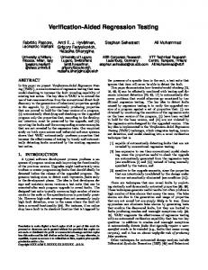
V. Heater Tests A. Apparatus The sheathed heaters for the neutralizer and discharge chamber cathodes will be provided by Aerojet to validate their manufacturing and fabrication processes. The electron emitting inserts will be installed to match the thermal mass to that of a completely assembled cathode. The cathodes will then be mounted on the heater test fixture, shown in figure 6, which allows simultaneous testing of up to six heaters. Ceramic insulators at the bottom provide electrical and thermal isolation against conducted heat. Stainless steel radiation shields provide protection from radiated heat. The test fixture will be installed in Vacuum Facility 65 at GRC. This is a 91 cm long by 48 cm diameter cryogenically pumped belljar with a glass dome. The facility is capable of a “no-load” pressure of 13 µPa, corrected for xenon. A photograph of the test facility is shown in figure 7. Radiation Shield
Ceramic Insulator Figure 6.—Heater test fixture.
DAC Components
Vacuum Facility
Power Supplies
Computer
Cryo Pump Figure 7.—Cathode heater cyclic test setup.
NASA/TM—2007-215036
7
Vacuum Chamber
Cathode Heater
+ -
Power Supply
D/A Converter
T/C Multiplexer
x6
Computer A/D Converter
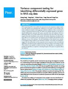
Figure 8.—Block diagram of heater test setup.
The heater test will be controlled by a data acquisition and control system (DAC). A computer sends commands to the heater power supplies through a multi-channel digital-to-analog converter. Test data for each heater are sent to the computer for display and storage through a multiplexer and an analog-to-digital converter. Heater currents are measured with isolated Hall effect sensors. Voltages are measured at the vacuum feed through to eliminate voltage drops. Finally, heater temperatures are measured with R-type thermocouples. A block diagram on the test setup is shown in figure 8.
B. Test Plan and Procedure The test sequence includes the several tests. First, the heaters will go through a bake-out to allow outgassing. Then, they will be subjected to a burn-in test and subsequently a current ramp test. These last two tests help assess performance and unit-to-unit repeatability. During the burn-in test, the heaters are subjected to a number of cycles (on for 6 min and off for 4 min) operating at 8.50 A which is the current level used for cathode ignition. During the current ramp test, they are operated with a current that slowly increases from 0.00 to 8.50 A. Finally, the heater will go into the cyclic life test. This test is like the burnin; however, the heaters are operated until they fail. The most common failure mode is an open circuit of the center conductor. The cyclic life test is a worst-case test and will subject the NEXT cathode heaters to orders of magnitude more cycles than required. The success criterion for the cyclic life test is heaters that meet or exceed the B10 lifetime of the ISS plasma contactor hollow cathode assembly. This is the statistical number of cycles at which 10 percent of the test heaters would fail after 6679 cycles.
Summary Life validation plans for the NEXT ion thruster include component verification testing. HVPIs were selected for verification because even though they are based on previous designs, they will be operated in a significantly different environment. Two HVPIs are currently undergoing a life validation test under worst-case test parameters (plus margin) such as voltage, temperature, and pressure conditions. After more than 10,000 hr of operation, only a slight increase in leakage current has been detected. The leakage current is about 1 nA which is five orders of magnitude lower than the 100 µA requirement. The cathode heaters for the NEXT thruster will also undergo a series of acceptance tests and a cyclic life test to evaluate reliability. Successful completion of these tests will ensure that these NEXT thruster components are of the expected quality and will also validate Aerojet’s manufacturing processes.
NASA/TM—2007-215036
8
References 1. Polk, J.E., et al., “Demonstration of the NSTAR Ion Propulsion System on the Deep Space 1 Mission,” IEPC–01–075, International Electric Propulsion Conference, October 2001. 2. Benson, S.W., Patterson, M.J., Vaughan, D.A., Wilson, A.C., and Wong, B.R., “NASA’s Evolutionary Xenon Thruster (NEXT) Phase 2 Development Status,” AIAA–2005–4070, Joint Propulsion Conference, July 2005. 3. Piñero, L.R., Hopson, M., Todd, P., and Wong, B., “Performance of the NEXT Engineering Model Power Processing Unit,” AIAA–2007–5214, Joint Propulsion Conference, July 2007. 4. Aadland, R.S., Frederick, H., Benson, S.W., and Malone, S., “Development Results of the NEXT Propellant Management System,” JANNAF Conference, 2005. 5. Monheiser, J., Aadland, R., and Wilson, F., “Development of a Ground Based Digital Control Interface Unit (DCIU) for the NEXT Propulsion System,” AIAA–2004–4112, Joint Propulsion Conference, July 2004. 6. Snyder, J.S., O’Connell, M.R., Fernandez, J.P., Wang, G., McNabb, R.S., and Crumb, D., “Vibration Test of a Breadboard Gimbal for the NEXT Ion Engine,” AIAA–2006–4665, Joint Propulsion Conference, July 2006. 7. Soulas, G.C., et al., “NEXT Ion Engine 2000-Hour Wear Test Results,” AIAA–2004–3791, Joint Propulsion Conference, July 2004. 8. Herman, D.A., Soulas, G.C. and Patterson, M.J., “Status of the NEXT Ion Thruster Long Duration Test,” AIAA–2007–5272, Joint Propulsion Conference, July 2007. 9. Van Noord, J. and Williams, G.J., “Life Assessment of the NEXT Ion Thruster,” AIAA–2007–5274, Joint Propulsion Conference, July 2007. 10. Mantenieks, M.A., “Status of 30-Centimeter-Diameter Mercury Ion Thruster Isolator Development,” NASA TMX-73514, November 1976. 11. Sovey, J.S., Zakany, J.S., and Manzella, D.H., “NSTAR High Voltage Propellant Isolator Test,” NASA/TM—2004-212921, February 2004. 12. Hart, S.L., et al., “Investigation and Development of a High Voltage Propellant Isolator for Ion Thrusters,” IEPC–2005–316, International Electric Propulsion Conference, October 2005. 13. Hamley, J.A., NSTAR Thruster Element Technical Requirements Document, ND-310, JPL Report D-13638, April 1997. 14. Patterson, M.J., et al., “Space Station Cathode Design, Performance and Operating Specifications,” IEPC–97–170, International Electric Propulsion Conference, August 1997. 15. Soulas, G.C., “Status of Hollow Cathode Heater Development for the Space Station Plasma Contactor,” AIAA–94–3309, Joint Propulsion Conference, July 1994. 16. Sengupta, A., et al., “Status of the Extended Life Test of the Deep Space 1 Flight Spare Ion Engine After 30,352 Hours of Operation,” AIAA–2003–4558, Joint Propulsion Conference, July 2003. 17. Hoskins, W.A., et al., “Development of a Prototype Model Ion Thruster for the NEXT System,” AIAA–2004–4111, Joint Propulsion Conference, July 2004. 18. Rawlin, V.K., et al., “NSTAR Flight Thruster Qualification Testing,” AIAA–98–3936, Joint Propulsion Conference, July 1998. 19. Soulas, G.C., Domonkos, M. T. and Patterson, M.J., “Performance Evaluation of the NEXT Ion Engine,” AIAA–2003–5278, Joint Propulsion Conference, July 2003. 20. Hoskins, W.A., Aerojet, Private Communication, November 2005. 21. Van Noord, J.L., “NEXT Ion Thruster Thermal Model,” AIAA–2007–5218, Joint Propulsion Conference, July 2007.
NASA/TM—2007-215036
9
Form Approved OMB No. 0704-0188
REPORT DOCUMENTATION PAGE
The public reporting burden for this collection of information is estimated to average 1 hour per response, including the time for reviewing instructions, searching existing data sources, gathering and maintaining the data needed, and completing and reviewing the collection of information. Send comments regarding this burden estimate or any other aspect of this collection of information, including suggestions for reducing this burden, to Department of Defense, Washington Headquarters Services, Directorate for Information Operations and Reports (0704-0188), 1215 Jefferson Davis Highway, Suite 1204, Arlington, VA 22202-4302. Respondents should be aware that notwithstanding any other provision of law, no person shall be subject to any penalty for failing to comply with a collection of information if it does not display a currently valid OMB control number. PLEASE DO NOT RETURN YOUR FORM TO THE ABOVE ADDRESS.
1. REPORT DATE (DD-MM-YYYY)
2. REPORT TYPE
01-12-2007
Technical Memorandum
3. DATES COVERED (From - To) 5a. CONTRACT NUMBER
4. TITLE AND SUBTITLE
NEXT Thruster Component Verification Testing 5b. GRANT NUMBER 5c. PROGRAM ELEMENT NUMBER 6. AUTHOR(S)
5d. PROJECT NUMBER
Pinero, Luis, R.; Sovey, James, S. 5e. TASK NUMBER 5f. WORK UNIT NUMBER
WBS 346620.04.05.03.13 7. PERFORMING ORGANIZATION NAME(S) AND ADDRESS(ES)
8. PERFORMING ORGANIZATION REPORT NUMBER
National Aeronautics and Space Administration John H. Glenn Research Center at Lewis Field Cleveland, Ohio 44135-3191
E-16216
9. SPONSORING/MONITORING AGENCY NAME(S) AND ADDRESS(ES)
10. SPONSORING/MONITORS ACRONYM(S)
National Aeronautics and Space Administration Washington, DC 20546-0001
NASA 11. SPONSORING/MONITORING REPORT NUMBER
NASA/TM-2007-215036; AIAA-20075276 12. DISTRIBUTION/AVAILABILITY STATEMENT
Unclassified-Unlimited Subject Category: 20 Available electronically at http://gltrs.grc.nasa.gov This publication is available from the NASA Center for AeroSpace Information, 301-621-0390 13. SUPPLEMENTARY NOTES
14. ABSTRACT
Component testing is a critical part of thruster life validation activities under NASA’s Evolutionary Xenon Thruster (NEXT) project testing. The high voltage propellant isolators were selected for design verification testing. Even though they are based on a heritage design, design changes were made because the isolators will be operated under different environmental conditions including temperature, voltage, and pressure. The life test of two NEXT isolators was therefore initiated and has accumulated more than 10,000 hr of operation. Measurements to date indicate only a negligibly small increase in leakage current. The cathode heaters were also selected for verification testing. The technology to fabricate these heaters, developed for the International Space Station plasma contactor hollow cathode assembly, was transferred to Aerojet for the fabrication of the NEXT prototype model ion thrusters. Testing the contractor-fabricated heaters is necessary to validate fabrication processes for high reliability heaters. This paper documents the status of the propellant isolator and cathode heater tests. 15. SUBJECT TERMS
Electric propulsion; Ion propulsion; Electrostatic propulsion 16. SECURITY CLASSIFICATION OF: a. REPORT
b. ABSTRACT
U
U
17. LIMITATION OF ABSTRACT c. THIS PAGE
U
UU
18. NUMBER OF PAGES
15
19a. NAME OF RESPONSIBLE PERSON
STI Help Desk (email:
[email protected]) 19b. TELEPHONE NUMBER (include area code)
301-621-0390 Standard Form 298 (Rev. 8-98) Prescribed by ANSI Std. Z39-18