sensing device with an optical sensing system that de- tects the reflection of a hand when it ..... restore a degree of articulation, (much like vibrato in a guitar or violin) while maintaining pitch quantization. As can be seen in Figure 6, which ...
Proceedings of the 2002 Conference on New Instruments for Musical Expression (NIME-02), Dublin, Ireland, May 24-26, 2002
The Termenova: A Hybrid Free-Gesture Interface Leila Hasan , Nicholas Yu, Joseph A. Paradiso Responsive Environments Group MIT Media Laboratory 1 Cambridge Center Cambridge, MA 02142, USA {leila, nhyu, joep}@media.mit.edu Abstract We have created a new electronic musical instrument, referred to as the Termenova (Russian for “daughter of Theremin”) that combines a free-gesture capacitivesensing device with an optical sensing system that detects the reflection of a hand when it intersects a beam of an array of red lasers. The laser beams, which are made visible by a thin layer of theatrical mist, provide visual feedback and guidance to the performer to alleviate the difficulties of using a non-contact interface as well as adding an interesting component for the audience to observe. The system uses capacitive sensing to detect the proximity of the player's hands; this distance is mapped to pitch, volume, or other continuous effect. The laser guide positions are calibrated before play with positioncontrolled servo motors interfaced to a main controller board; the location of each beam corresponds to the position where the performer should move his or her hand to achieve a pre-specified pitch and/or effect. The optical system senses the distance of the player's hands from the source of each laser beam, providing an additional dimension of musical control. Keywords Theremin, gesture interface, capacitive sensing, laser harp, optical proximity sensing, servo control, musical controller INTRODUCTION The Theremin, invented by Leon Theremin in 1919 [1], is widely regarded as the first successful electronic musical instrument. It uses a heterodyned variable frequency oscillator controlled by the proximity of the player's hand or body to a capacitive sensing element, such as an antenna. It is also the first known example of a free-gesture musical interface, where there is no physical contact between the player's body and the instrument. Perhaps due to its novelty, this type of interface has garnered periodic interest over the last century, with an explosion in popularity in recent years, as work with electric field sensing, infrared proximity detection, and computer vision have produced variations on the Theremin and evolved entirely new free-gesture interfaces that use computers to interpret gestural cues at a higher musical level. Interest has also been augmented by the rise of popular electronic music. As more performances occur in this genre, there is an increasing need for interfaces that produce an interesting spectacle for an audience, in contrast to the behind-the-scenes knob-twiddling common in
heavily sequenced electronic concerts. Furthermore, there is a desire for interfaces that allow observers to make connections between what is going on in the artist’s head with what is coming into their ears. Expressive, spectacle-creating instruments such as the Theremin have been benefiting from this trend, as many new variations on this old idea have recently appeared. One example of this is the Dimension Beam from Interactive Light [2], which infers the distance to the hand simply via the amount of reflection from an invisible infrared (IR) source [3]. Another is the Palm Driver (formerly the Twin Towers), developed by Leonello Tarabella and Graziano Bertini at CNUCE in Pisa. This device also infers proximity from the intensity of IR reflection, but sports an array of IR detectors at each hand to sense two axes of tilt as well [4]. Other non-contact interfaces include the Videoharp, developed by Dean Rubine and Paul McAvinney of Carnegie Mellon University, which senses finger gestures by examining the pattern of shadows projected by the player's hand onto a photodiode array [5]. At the MIT Media Lab, Paradiso and colleagues have developed an array of free-gesture instruments [6] that are based on electric field sensing, like the Theremin (e.g., the Sensor Chair and the Gesture Wall), and low-power microwave radars. Although perhaps an enthusiastic audience once more exists for performances with noncontact instruments, there is a striking lack of virtuosic players; common applications of such controllers are in simple shaping of expressive sound or as musical therapy for the severely disabled [7]. Indeed, the world has produced few Clara Rockmores, whose Theremin performances thrilled audiences across several decades [8]. Playing the Theremin or other free-gesture interfaces, not just for special effects, but as complex lyrical instruments, requires precise skill, an exceptional sense of pitch, and a steady hand. The performer gets only audio feedback, and waving one's hands in the air with precision is a difficult skill to master; the playing space often has no visible structure, and there is, by definition, no physical contact, hence tactile reference. Recent research [9] has indicated that better playing accuracy can be achieved from free-gesture instruments if they incorporate simple haptic feedback, such as a spring constant acting between the hand and Theremin antennae. This approach, however, entails a mechanical link between player and instrument, introducing its own set of complications as well as destroying the special appeal of an untethered performance.
NIME02-01
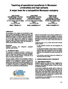
Figure 2: A Laser Module
Figure 1: System Diagram (above) and as built (below)
This paper documents the design and implementation of a new type of electronic musical instrument, given the name Termenova (Russian for ``daughter of Theremin''), which combines the non-contact sensing methods of the Theremin with an array of dynamic laser guides. These guides, or visual frets, offer visual feedback in lieu of physical, and define the play space to the performer by marking the locations of known pitches. The system can calibrate the positions of the laser guides for each performer and for any set of desired frequencies, as well as dynamically re-tune or reposition during play. Additionally, each guide can sense the position of the player's hand along the laser beam, adding another dimension of continuous control. These additional channels of articulation can be configured to map to any musical elements the performer desires, creating an instrument of far greater complexity and scope than a traditional Theremin. SYSTEM OVERVIEW The Termenova retains the unique and elegant noncontact properties of the Theremin, while providing a perceivable structure to the performer. The system consists of an electric field sensing device interfaced to a laser positioning system. The player stands with the laser array between them and the sensing device, using the laser array as a guide for placement of their hands during play and for continuous control in the vertical plane (Figure 1 shows an overview of the system setup, with the room lights on and lasers off). The electric field sensor acts as a continuous proximity sensor that maps to pitch, with the lasers marking out known distances from the antennae. Moving one's fingertips near a laser beam's
location produces the pitch that is specified by that fret. The response of any capacitive sensing system varies widely; environmental factors as well as characteristics of the performer, such as their capacitive coupling, their play method and body posture, will all affect the relationship between the physical laser beam positions and the corresponding pitches. To allow for calibration for such effects, each laser is equipped with a reflectance sensor tuned to the modulation frequency of its associated light that can unambiguously detect the presence of a performer's hand. As the performer moves his or her hand (in play position) through the laser beams, the capacitive pickup voltage is recorded as each virtual fret position is passed. To compensate for tuning drift, the physical positions of the frets, which each sit atop an individually servo-controlled robotic carrier, are modified so the beams represent hand locations for a known set of pitches. There is also the potential to play the Termenova like a harp, as in Jean Michel Jarre's “Laser Harp” [10]. In this mode, an interrupted laser beam corresponds to 'plucking' a visual string, with the sound being modulated by both the capacitively-detected hand position and the position of the hand along the laser axis, inferred through the amplitude of reflected illumination. Thus the Termenova can be played as a discrete, continuous, or mixed discrete and continuous pitch instrument. DESIGN AND IMPLEMENTATION The Termenova contains a set of laser modules (as seen in Figure 2) that are capable of moving independently on a shared track and communicating with a main controller. This separate main controller regulates the entire system, using data from the modules and from the fieldsensing device to determine each module’s desired state. An overview of each subsystem is given below; details for each can be found in Leila Hasan’s Masters thesis [11]. Every module contains a modulated laser with matched synchronous receiver; the receiver detects the light reflected from an obstruction of the beam. Each laser is modulated at a distinct frequency, hence the receivers detect only the light reflected back from its own module.
NIME02-02
Computer or Audio Output Device
Module Bus
Main Controller
position data photosensor data laser state Electric Field Sensing Device
module ID state? new position laser on/off Module
Figure 3: System Block Diagram
The sensors are sensitive enough to detect barehanded reflections up to several feet away. A commercial theatrical mist generator is coupled to a set of capillary tubes routed to each module, injecting mist along the axis of each laser to make the beam visible. The mist has very little effect on the optical pickup, and the reflection from the hands is still strongly dominant. To enable independent movement, each module is equipped with its own miniature servomotor. The motor shaft is coupled to a pinion that traverses a rack; the shaft is also coupled to a multi-turn potentiometer, which provides absolute position data. On every board is a microcontroller, which transmits and receives data from the laser and motor systems. Additionally, it communicates with a main controller board via a serial bus, with a single receive line and single transmit line shared by all the modules (see Figure 3). Laser System The laser system contains a visible-wavelength ~635nm red laser unit and a synchronous detector, both driven by a single signal line from the microcontroller. The laser system provides the visual guides and also senses the presence and proximity of an object blocking a beam. A set of 5 mW laser diodes is used for the visible array of frets. Such laser diodes are readily available, inexpensive, safe, and relatively simple to control and drive; all these were important considerations in the original fullup design, as it called for 10-20 modules, each containing a full set of parts, including a laser. A laser diode/driver package was found whose electronics were easily modified to accommodate being driven at the desired carrier frequencies, in the vicinity of 5kHz. A combined photodiode and transimpedance amplifier are used to sense the reflected laser. A 2 cm lens with appropriate focal length is used to collect the light and focus it onto the photodiode surface. Because the proximity measurements are affected by the albedo of the hands, inferring proximity by the amount of detected reflection is not true rangefinding [12]. The reflection technique is much simpler to implement, however, and the resulting relative measurements are adequate for this application.
Synchronous Demodulation Synchronous demodulation refers to a simple matched filtering process by which a received signal is multiplied by the modulation of the excitation source (which beats it down to baseband), then low-pass filtered to isolate the detected excitation. It is used in many applications, such as AM radio and spectroscopy, to find a desired signal buried in a sea of unwanted signals and noise. In this project, the original signal is a constant (the laser driving voltage), which is chopped by a carrier frequency of approximately 5 KHz. The signal from the photodiode is amplified and demodulated directly to baseband via a synchronously-driven analog switch [11]. A lowpass filter, with cutoff at 100Hz, selects only signals from the transmitted laser, eliminating contributions from any out-of-band ambient illumination. This superior background rejection from synchronous demodulation, together with the spatial precision of the narrow, 2mm laser beam, distinguish this system from standard, commercial, IR non-contact interfaces, such as the Dimension Beam from Interactive Light [2]. Motor System For the motor system, an inexpensive, absolute positioning system for the entirety of the track was desired. To achieve this, the method employed by hobbyist RC servos was considered; these incorporate robust position control using only a potentiometer as feedback, and are extremely inexpensive ($10-$30). However, they tend to be capable of moving a maximum of only one half turn of the servo. An RC servo was modified to retain a powerful motor and useful gear train, but with the potentiometer and electronics removed. An inexpensive 20-turn vertical trimpot was coupled to the shaft, and its output fed to a 16-bit analog to digital converter. Ideally, a 16-bit A/D corresponds to over 65,000 positions. With a gear diameter of 0.6'' and a 20-turn pot, this becomes 65,000 over a 37'' long area of travel, which translates to .0006''/bit. This is a gross overestimation of the capabilities of the system, as it is far from ideal. However, even assuming a worst case scenario of only 12 good bits from the 16-bit A/D, there are still about 4000 positions, which for 37'' of travel corresponds to .009''/bit, which is still amply accurate for the needs of the system, as the average human being can not visually discern a hand movement of 1/100''. For motor control, the only input to the controller is absolute position, acquired from the potentiometer. The microcontroller applies its integral pulse-width modulation (PWM) to the motor drive voltage, which controls the torque of the motor and approximately controls the speed, since the track is relatively uniform. Position control using only position data has the potential to result in instability, but with the motors moving relatively slowly and the gain kept reasonably low, robust position control is possible. This was realized by a digital proportional+derivative (PD) controller [13].
NIME02-03
Module Control The microcontroller, here a PIC16F876, communicates via a UART to the main control board on a serial bus that is shared between all modules. The main board polls all boards in succession, logging data values and sending new positions or states when appropriate. To control the motor, the PIC gets a reading from the 16-bit A/D and drives the motor with the PWM module and an output pin to specify direction. Each PIC uses an internal timer to generate a distinct modulation frequency, which is used by the laser diode and synchronous demodulator (as each module’s laser ran at a different frequency there was no mutual interference between beams). The output of the synchronous demodulator is read by an analog pin of the PIC, and compared to the pre-determined threshold value to determine if an object is in the pathway of the beam. While the threshold value is exceeded, the analog intensity data is transmitted, providing the mapping software with a continuously controllable parameter corresponding to vertical hand position.
Calibration During calibration, the main controller gets readings from the ClassicFish and modules, and creates a mapping of frequencies to module positions. From this mapping and the list of desired pitches, the controller determines a new set of positions for the modules based on a piecewise linear fit algorithm. The algorithm works as follows: •
The modules shall be referred to as mod1, mod2, ...modn in order of distance from the capacitance sensor.
•
The modules will be placed so that mod1 and the modn are at the extreme ends of the track, and the others are dispersed between.
•
An assumed frequency will be mapped to each of the modules based on information taken from the ClassicFish during the first pass of the player through the playing area during calibration.
•
Suppose mod1's desired pitch lies somewhere between the pitches measured at the positions of mod1 and mod2. A simple linear relation based on their current positions and pitches will be determined as follows:
pnew = ( f desired − f1 )
p2 − p1 + p1 f 2 − f1
Where: Figure 4: Capacitive Transmit Mode
Capacitive Sensing The ClassicFish [14] is an analog-demodulated electric field sensing device created at the MIT Media Lab, which uses the same fundamental principles as the Theremin, but exploits other sending modes to provide a more robust, longer-ranging proximity sensor. The Theremin detects the change in capacitance seen by the antenna when it capacitively couples to the player's body. The ClassicFish, in transmit mode (the mode that is used in the implementation of this system) drives the body of the player with a transmit signal; the player's entire body then acts a transmitting antenna for this signal, and the amplitude of the received signal at the receive antenna corresponds to the body’s proximity [14], as shown in Figure 4. When using the ClassicFish in transmit mode, a sensing distance of several feet can be achieved. Additionally, this system is far less prone to drift than common with the “loading” mode used by the Theremin, as it does not contain any highly sensitive, drift-prone analog heterodyning electronics, and responds only to the transmitting player, not to other objects in the vicinity. Interface Board The main controller board interfaces between the ClassicFish, the module controllers, and the output device. The controller has vastly different functions during calibration and play.
•
f1
is the current frequency at mod1.
•
f2
is the current frequency at mod2.
•
p1
is the current position of mod1.
•
p2
is the current position of mod2.
•
f desired
•
pnew
is the desired frequency for that module.
is the new position.
After determining this for all the modules, the controller instructs the modules to move to the new positions. The player passes their hands through the play area for calibration for the second time, and a new set of frequencies is recorded. The piecewise linear fit is repeated, which results in a close enough approximation to the actual positions, which define the desired pitches.
Play During play mode, the main controller provides the output device with continuous updates on the pitch data received from the ClassicFish and/or from the laser guides, depending whether the system is in continuous, discrete, or hybrid mode. The lasers on any modules may be commanded to be on or off at any time. This has several applications: e.g., having the system teach the player a melody by selectively lighting the lasers and having the user “play”' the notes as they are highlighted, or providing an interesting visual effect for performance. The output of the main controller can be processed by an external program to produce interesting mappings and
NIME02-04
additional effects that go well beyond the simpler quantization of pitch described above. As seen in the mapping example below, the lasers also provide visual markers for places where the performer can place their hand to achieve a specific effect. MAPPINGS Although this instrument can be used in many novel ways, the first mapping that we attempted began as an extension of the Theremin. Like the Theremin, the pitch of the lead voice was continuously and directly controlled by the electric field sensor. Although the laser beams provide extra dimensions of control not possible with the original instrument, these degrees of freedom were mapped in such a way that the playing model of the original Theremin is unaltered — the fundamental mapping of pitch onto a single spatial axis was not violated. All coding was done in C++ within Perry Cook's Synthesis Toolkit framework [15]. For the lead voice, a classic analog string sound was synthesized using twin 1%-detuned square wave oscillators. Pulse widths are modulated using two 2-Hz LFOs, 180 degrees out of phase. The resultant signal was then filtered with a resonant low-pass filter. Breaking any of the laser beams retriggered the lead voice, resetting envelopes and LFOs. Breaking a beam also quantized lead pitch to predetermined note values. Note that the spatial position of each laser beam also coincided with a specific non-quantized pitch derived from the electric field sensor; therefore, for each beam, proper calibration was necessary to ensure that these nonquantized pitches are musically coherent with the quantized pitch. Currently, breaking a laser beam quantizes the lead voice to the nearest diatonic pitch; a very simple arrangement. Alternately, with more evolved mappings, breaking a laser beam could result in more complex intervals, arpeggios, or chords to be played. The laser beams are also capable of inferring the distance to the player's hand. Here, this axis, which is perpendicular to the pitch axis, can be used to continuously control timbre. As the player's hand moves along this timbre axis, a specific synthesis parameter can be modulated. Each beam is mapped to a different parameter (waveshaping with an exponential function, ring modulation, filter cutoff, and rhythmic noise generation), presenting a very limited but still interesting class of pitch and timbre possibilities. Breaking the laser beam also adds the quantized pitch into a feedback delay line, which is re-synthesized using an FM bell voice. This allows the player to create thick harmonic structures. Finally, a single laser is reserved to control the volume of the lead voice. This laser can be broken with the player's other hand and, like the original Theremin, moving the player's hand up and down along this beam controls the volume of the lead voice. The present mapping also has a latching function, where the timbral parameter adjusted by moving the hand along a laser beam is latched when the hand is removed, allowing the player to
progressively evolve the sound quality of the instrument during performance. Our initial trials with this mapping have already resulted in several gestural styles; e.g., where hands and arms together are used to "play" several simultaneous laser beams and explore complex timbral shaping. As it's trivial to add more axes of capacitive sensing, we are now making a mapping that employs an additional degree of control, orthogonal to the pitch axis. This opens another continuous modulation available everywhere, accessed by pushing hands across the laser array and allowing another expressive parameter (e.g., distortion, or a timbral crossfade) to be accessed by the player. Capacitive Sensor hand hand moves moves forward backward
Optical Sensors
0
1
Time (s)
2
Figure 5: Capacitive and Optical Detector Response
CONCLUSIONS The resulting system is extremely responsive in both the capacitive and optical sensing modalities. A graph of what is seen by the various sensors as a hand is passed back and forth over three beams can be seen in Figure 5. As can be noted in the data, the detectors are able to see individual fingers on the hand as it passes over them, palm down (of course, a much more narrow spatial discrimination can be obtained by running single fingers through the beam as opposed to entire hands). The range of both the capacitive and optical detectors is several feet, which allows for a large playing area. For this system, with so many channels of continuous control, the challenge is in effectively mapping all parameters to engaging musical response. If there are too many ill-defined degrees of freedom, then it becomes virtually impossible to play the system as an instrument or even a useful effects generator. This critical characteristic of the interface is mainly controlled by the mapping software; any musical mappings must keep the interactions intuitive and learnable, while not becoming so overly complex that they render the system unplayable. That said, it may be desirable to add appropriate degrees of freedom, as long as this is done in a controlled, intuitive manner. One possible augmentation might be to add
NIME02-05
then be the performer that is being used as the interface between the computer and the music-creating device. ACKNOWLEDGMENTS We thank the research sponsors of the MIT Media Lab, for supporting our work, acknowledge Matthew Hancher for lending technical expertise, and thank Rebecca Zook and Farhad Ebrahimi for musical guidance. We also thank our colleagues in the Responsive Environments group for various bits of assistance and their tolerance of our misting apparatus. REFERENCES [1] Glinsky, A., Theremin: Ether Music and Espionage, University of Illinois Press, 2000.
[2] Rich, R., “Interactive Light Dimension Beam,” Electronic Musician, Vol. 12, No. 7, July 1996, pp. 154-159.
[3] Fisher, C.R. and Wilkinson, S., “DIY: Build the EM Optical Theremin,” Electronic Musician, Vol. 11, No. 5, May 1995, pp. 58-64.
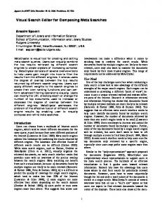
Figure 6: Playing the Terminova
another axis of capacitive sensing, making the playspace truly 3-dimensional, instead of mostly planar, as it is in the current implementation. Another possibility is to add a pedal to control the volume; volume control is of vital importance when playing a continuous controller, as without it, discrete changes are impossible. However, in the current system, although it latches its value when the hand is removed from the beam, the volume is controlled by the left hand at the outmost laser (in analogy to the left-hand volume antenna on the Theremin). Changing the volume over to a pedal would free up the left hand for other control possibilities. Experienced Theremin players (e.g., [8]) have developed sophisticated techniques for rapidly changing pitch by adjusting the configuration of their hand (a visual vocabulary looking almost like Buddist mudras [16]), hence delegating fast control to the fingers. When the hand is above a laser “fret”, this degree of control is inhibited in favor of the programmed pitch. Allowing transverse hand motion above a laser to produce small, dynamic deviations in the fret’s assigned pitch would restore a degree of articulation, (much like vibrato in a guitar or violin) while maintaining pitch quantization. As can be seen in Figure 6, which shows the Termenova in performance, it is a visually captivating device. Accordingly, there are other visual aspects that can be further explored, such as synchronizing dynamic laser effects to musical events. Also, a person could be taught how to play a piece of music by a computer, which could turn on only the laser that corresponds to the pitch that is next to be played, making the lasers highlights for the next note. If there are continuous pitch changes in the music, the computer could control a motor and make the laser move appropriately; the player would then follow the laser with their hand, which, if tuned correctly, would create the desired sound. In this case, it would
[4] Tarabella, L., and Bertini, G., "Original Gesture Interfaces for Live Interactive Multimedia Performances," in Proceedings of the Journées d’Informatique Musicale, Lyon, France, June 6-7, 1997, pp. 41-45.
[5] Rubine, D. and McAvinney, P., “Programmable Fingertracking Instrument Controllers,” Computer Music Journal, Vol. 14, No. 1, 1990, pp. 26-41.
[6] Paradiso, J. “The Brain Opera Technology: New Instruments and Gestural Sensors for Musical Interaction and Performance,” Journal of New Music Research, Vol. 28, No. 2, 1999, pp. 130-149.
[7] Ellis, P., “The music of sound: a new approach for children with severe and profound and multiple learning difficulties,” British Journal of Music Education, 14:2, pp. 173–186.
[8] Rockmore, C., The Art of the Theremin, CD on Delios International, Santa Monica, CA, 1987.
[9] O’Modhrain, M.S., Chafe, C., “The Performer-Instrument Interaction: A Sensory Motor Perspective,” in Proceedings of ICMC 2000, Berlin, Germany, August 2000, pp. 145-148.
[10] Laserharp. http://www.jeanmicheljarre.net [11] Hasan, L., “Visual Frets for a Free-Gesture Interface,” MIT MEng Thesis, MIT EECS Department and MIT Media Lab, May 2001.
[12] Paradiso, J.A., Hsiao, K., Strickon, J., Lifton, J. and Adler, A., "Sensor Systems for Interactive Surfaces," IBM Systems Journal, 39(3&4), October 2000, pp. 892-914.
[13] Nise, N.S., Control Systems Engineering, Wiley 2000. [14] Paradiso, J., Gershenfeld, N., “Musical Applications of Electric Field Sensing,” Computer Music Journal, Vol. 21, No. 3, Summer 1997, pp. 69-89.
[15] Cook, P.R., Scavone, G.P., “The Synthesis ToolKit, (STK), version 2.1,” in Proceedings of ICMC 1999, Beijing, China, October 1999, pp. 164-166.
[16] Saunders, E.D., Mudra, Princeton University Press, 1985.
NIME02-06