Materials Science Forum ISSN: 1662-9752, Vol. 635, pp 23-31 doi:10.4028/www.scientific.net/MSF.635.23 © 2010 Trans Tech Publications, Switzerland
Online: 2009-12-03
NiMn-Based Metamagnetic Shape Memory Alloys R. Kainuma1,a, K. Ito2, W. Ito1, R.Y. Umetsu1, T. Kanomata3 and K. Ishida2 1
Institute of Multidisciplinary Research for Advanced Materials (IMRAM), Tohoku University, Sendai 980-8577, Japan 2 Department of Materials Science, Tohoku University, Sendai 980-8579, Japan 3 Faculty of Engineering, Tohoku Gakuin University, Tagajo 980-8579, Japan a
[email protected]
Keywords: metamagnetic shape memory, NiMnIn, NiMnSn, powder metallurgy
Abstract. The magnetic properties of the parent and martensite phases of the Ni2Mn1+xSn1-x and Ni2Mn1+xIn1-x ternary alloys and the magnetic field-induced shape memory effect obtained in NiCoMnIn alloys are reviewed, and our recent work on powder metallurgy performed for NiCoMnSn alloys is also introduced. The concentration dependence of the total magnetic moment for the parent phase in the NiMnSn alloys is very different from that in the NiMnIn alloys, and the magnetic properties of the martensite phase with low magnetization in both NiMnSn and NiMnIn alloys has been confirmed by Mössbauer examination as being paramagnetic, but not antiferromagnetic. The ductility of NiCoMnSn alloys is drastically improved by powder metallurgy using the spark plasma sintering technique, and a certain degree of metamagnetic shape memory effect has been confirmed. Introduction Since Ullakko et al. [1] first reported a magnetic field-induced strain (MFIS) in a ferromagnetic single crystal of Ni2MnGa in 1996, the research in this field has drastically progressed and a huge MFIS of over 9% [2] has recently been reported. The MFIS in the Ni2MnGa alloys, however, is not due to the shape memory effect (SME) accompanying martensitic transformation, but rather to rearrangement of martensite variants by twin boundary migration in the martensite (M) phase. This twin boundary migration induced by a magnetic field is caused by the large crystalline magnetic anisotropy energy of the M phase with low crystal symmetry. Details on the MFIS in the Ni2MnGa alloys have recently been reviewed by Marioni et al. [3]. Although a large output strain and a rapid response can be confirmed in the Ni2MnGa alloy, the output stress is principally less than 5 MPa [4]. Furthermore, significant brittleness of the Ni2MnGa single crystal is a serious problem preventing application of this material. On the other hand, some trials using phase transformation itself to obtain an MFIS have been reported [5-7]. In Ni2MnGa alloys, however, a huge magnetic field is required to obtain magnetic field-induced transformation because both the P and M phases show ferromagnetism and the saturated magnetization of the M phase is comparable to that of the P phase [8]. Up to now, many Ni-based magnetic shape memory alloys (MSMAs) with similar magnetic properties, such as NiMnAl [9,10], NiCoAl [11,12], NiCoGa [12,13], NiFeGa [14,15], etc., have been reported and the characteristic features of their magnetic and martensitic transformations have been clarified. Recently, we have found an unusual transformation from a ferromagnetic P to a weak magnetic M phase in the NiMnIn- and NiMnSn-based Heusler alloys [16], which shows behaviors completely different from the previous MSMAs. These new types of magnetic shape memory alloys show many interesting phenomena derived from the unique transformation, such as magnetic field-induced phase transition, the inverse magnetocaloric effect [17,18], the giant magnetoresistance effect [19,20], giant
This is an open access article under the CC-BY 4.0 license (https://creativecommons.org/licenses/by/4.0/)
24
Ferromagnetic Shape Memory Alloys II
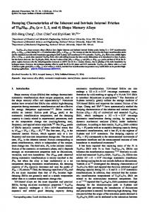
magnetothermal conductivity [21], etc. Details on the basic physical properties of the NiMnZ Heusler alloys, including the NiMnGa alloys, have recently been reviewed by Planes et al. [22]. In this paper, the magnetic and martensitic properties for NiMnSn and NiMnIn alloys are reviewed and our recent work on powder metallurgy for the NiCoMnSn alloy is introduced. Magnetic properties in the NiMnSn and NiMnIn alloys [23, 24] (1) Phase diagrams Figure 1 shows the phase diagrams in the Ni2Mn1+xSn1-x [23] and Ni2Mn1+xIn1-x [24] reported by Kanomata et al.. The martensitic transformation appears in the high concentration region of x and the transformation start temperature Ms or the reverse transformation start temperature As drastically increases with increasing x. On the other hand, the magnetic transformation temperature in the P phase Tc is almost independent of the concentration, while that in the M phase Tc’ apparently decreases with increasing x in both alloy systems. In both systems, many kinds of crystal structures including the long period stacking layered structures, such as 2M, 10M, 14M and 4O, have been reported for the martensite phase, [25,26] while that for the P phase is the L21 Hesler structure. As mentioned later, in the high concentration region of x shown in Fig.1 the magnetic property in the higher temperature region of the martensite phase is paramagnetic and some change in the magnetic properties occurs at the Tc’ during cooling. The magnetic condition for this low temperature state is still unknown, but seems to be in a spin-glass-like state.
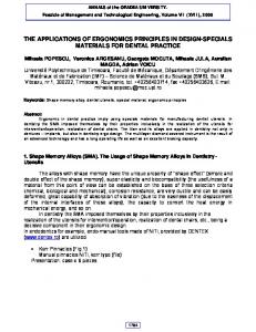
Fig. 1: Phase diagrams of the Ni2Mn1+xSn1-x [23] and the Ni2Mn1+xIn1-x [24], where Para, Ferro, and S.G.-like mean paramagnetic, ferromagnetic and spin glass-like states, respectively, and A and M indicate the austenite and martensite phases, respectively. (2) Magnetic properties Very recently, Kanomata et al. have reported the magnetic properties of the P phase for the NiMnSn and NiMnIn alloys [23, 24]. They found that the magnetic moments per formula unit m at 5 K for Ni2Mn1+xSn1-x and Ni2Mn1+xIn1-x estimated from the spontaneous magnetization can be plotted to the x as shown in Fig. 2(a) and (b), respectively. In the both cases, it is seen that the values of the magnetic moment of the samples in the M phase region is relatively smaller than those in the P phase region. It is very interesting to note that the m in the P phase region linearly decreases with increasing x in the NiMnSn system, while increasing in the NiMnIn system, and that on the contrary, the m in the M phase region decreases with x in both systems. It should be also noted that the magnetic moments in the
Materials Science Forum Vol. 635
25
stoichiometric Ni2MnSn and Ni2MnIn (x=0) alloys are almost the same at about m = 4. Kanomata et al. have suggested that while the neighboring Mn atoms at the Mn sites are ferromagnetically coupled in the both cases, the magnetic coupling between the neighboring Mn atoms at the different sites, namely, the Mn and the In sites, of the NiMnSn alloys is clearly different from that of the NiMnIn alloys. That is, the magnetic moment of the Mn atoms substituted at the In sites in Ni2Mn1+xIn1-x alloys is ferromagnetically coupled to the magnetic moments of the Mn atoms at the Mn sites, whereas the magnetic moment of the Mn atoms on the Sn sites in Ni2Mn1+xSn1-x alloys is antiferromagnetically coupled to the magnetic moments of the Mn atoms on the Mn sites. From the drastic change in the magnetic moment induced by the martensitic transformation, it is clear that the magnetic properties of these alloys are strongly affected by the lattice distortion and the atomic distances between the neighboring atoms. Recently, Şaşioğlu et al. [27] have theoretically studied the pressure dependence of exchange interaction in Ni2MnSn within the framework of the density-functional theory. According to the results of their calculations, the ferromagnetic interaction JBB between two Mn atoms at the Mn sites increases with pressure for interatomic Mn-Mn distance (rnn) ranging from 4.2 Å to about 3.7 Å with a maximum around 3.7 Å. Passing through the maximum around 3.7 Å, JBB is found to decrease abruptly with decreasing rnn . Furthermore, they showed that the ferromagnetic Ni-Mn interaction is almost independent of pressure. The appearance of the M phase with a small spontaneous magnetization in Fig. 2 may be attributed to the abrupt increase of the antiferromagnetic interaction JBD and the abrupt decrease of the ferromagnetic interaction JBB. The reason why the concentration dependence in the magnetic moment for the P phase of the NiMnSn system is so different from that of the NiMnIn system is unknown, but the difference in the interatomic Mn-Mn distance may be one of the most important factors for the origin of the difference. Very recently, Planes et al. have reported a similar relation in the total magnetic moment for NiMnZ (Z:Ga, In, Sn and Sb) and pointed out that the data for these magnetic moments plotted to the electron concentration nearly follow the Slater-Pauling (SP) curve with the same slope. [22]
Fig. 2: Concentration dependence of the total magnetic moment per formula unit, μm, at 5 K for the Ni2Mn1+xSn1-x [23] and the Ni2Mn1+xIn1-x [24]. The solid line in the figure is the curve calculated using the simple model indicated in the Ref.[23]. One of the most important and interesting questions regarding the magnetism of these alloys is which magnetic property the M phase with the low magnetization possesses, paramagnetic or antiferromagnetic. In order to answer this question, Mössbauer examination using radioisotope 57Fe
26
Ferromagnetic Shape Memory Alloys II
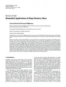
was performed for the NiMnSn alloy. [28] Figure 3(a) shows the DSC and thermomagnetization (M-T) curves obtained for the Ni50Mn36.5Sn1357Fe0.5 alloy used for the Mössbauer examination. As shown here, since the Tc and the Tc’ in the P and M phases are about 309 and 235 K and the Ms and the martensitic transformation finishing temperature Mf are about 307 and 278 K, respectively, the measured temperatures Tm = 312 and 264 K are located in the paramagnetic P state and in the M state with the low magnetization, respectively. As exhibited in Figs. 3(b) and 3(c), showing a simple singlet as well as the spectrum from the paramagnetic P phase at 312K, the Mössbauer spectrum obtained from the M phase at 264K suggests that the M phase with the low magnetization is paramagnetic. Very recently, we have confirmed that in the NiMnIn alloy as well, the M phase with the low magnetization just below Mf is paramagnetic, showing a similar singlet in the Mössbauer spectrum for the Ni50Mn34.3In15.257Fe0.5 alloy. [29] For the M phase below the Tc’, a ferromagnetic hyperfine field was observed in the spectra of both systems.
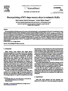
Fig. 4: Thermomagnetization curves in magnetic fields of H = 0.05 and 7 T (a) and magnetization curves at various temperatures (b) in the Ni45Co5Mn36.6In13.4 alloy. [30] Fig. 3: (a): DSC and thermomagnetization curves for the Ni50Mn36.557Fe0.5Sn13 alloy. ZFC and FC M-T curves were measured during heating after the specimen was cooled down to a low temperature in zero magnetic field, and during cooling in the applied magnetic field, respectively. (b) and (c): Mössbauer spectra obtained at 312K and 264K for Ni50Mn36.557Fe0.5Sn13 alloy, respectively. [28] Metamagnetic shape memory effect [30] Figures 4 (a) and (b), respectively, show the M-T and magnetization-magnetic field (M-H) curves of the Ni45Co5Mn36.6In13.4 alloy, where the applied magnetic field for the M-T curves were 0.05 and 7 T. The
Materials Science Forum Vol. 635
27
substitution of Co for Ni results in a drastic increase of the Tc in the P phase and a decrease of the Tc’ in the M phase and the difference in magnetization between the P and M phases under 7 T reaches about 90 emu/g at around 300 K. Furthermore, the Ms temperature decreases about 25 K with application of the magnetic field of 7 T due to the contribution of the Zeeman energy to the ferromagnetic P phase. As shown in Fig. 4(b), the magnetic field-induced transformation, i.e., metamagnetic phase transition, was confirmed at 270 and 290 K. It is worthy to note that the “reverse” transformation to the P phase, which occurs through heating in the conventional shape memory effect, is induced by the application of a magnetic field. This means that in this alloy the application of a magnetic field corresponds to “heating” and that the shape memory effect can be expected to occur by application of a magnetic field as well as by heating. The shape memory effect induced by a magnetic field was examined by the three-terminal capacitance method with the Ni45Co5Mn36.7In13.3 specimen. Figure 5 shows the recovery strain induced by a magnetic field at 298 K, where a compressive pre-strain of about 3% was applied in the direction plotted with a filled circle in the stereographic triangle shown in Fig. 5 and the magnetic field was applied vertically to the compressive axis of the specimen. The recovery strain started to increase at about 2 T, rose sharply at about 3.6 T, and then gradually increased to 8 T with an increasing magnetic field. A recovery strain of about 2.8%, almost equal to the pre-strain of 3%, was obtained with a magnetic field of 8 T. However, only a very small change of length was observed from about 3 T when the magnetic field was removed. We propose that the SM effect due to magnetic field-induced reverse transformation (MFIRT), that is a metamagnetic transition, be called the “metamagnetic shape memory effect (MMSME)” and that such an SMA be termed a “metamagnetic shape memory alloy (MMSMA)”. In the MMSME which needs no temperature change, a rapid response to an input signal is expected. Recently, Sakon et al. [31] have reported that the same Ni45Co5Mn36.7In13.3 single crystal shows an almost perfect MMSME for a single magnetic field pulse of 200 Hz, whose characteristic features are similar to those in static magnetic field.
Fig. 5: Recovery strain at 298 K induced by a magnetic field for the Ni45Co5Mn36.7In13.3 alloy in which a compressive pre-strain of about 3 % was applied, where the magnetic field was applied vertically to the compressive axis of the specimen and the length change parallel to the compressive axis was measured. Shape recovery is due to magnetic field-induced reverse transformation, which is termed the metamagnetic shape memory effect. [30]
Powder metallurgy for the metamagnetic SMA [32] The MMSME has also been confirmed in a textured polycrystalline Ni43Co7Mn39Sn11 alloy other than the NiCoMnIn single crystal. [33] Although the NiCoMnSn alloy system, which includes no expensive elements, may be the most promising MMSMA candidate for future industrial applications, the low ductility of polycrystalline specimens is still one of the most serious problems. Very recently,
28
Ferromagnetic Shape Memory Alloys II
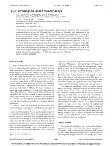
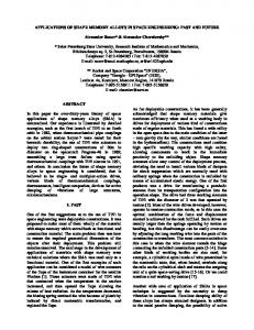
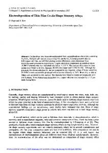
we have tried powder metallurgy for the Ni43Co7Mn39Sn11 alloy in order to improve its ductility. Details of the examination procedures are described in a previous paper [32]. The Ni43Co7Mn39Sn11 powder specimen was obtained by using conventional nitrogen gas atomization under an argon atmosphere and a gas pressure for atomization of about 1.5 to 5 MPa. After annealing at 1173 K for 24 h, the powder was sintered by the spark plasma sintering (SPS) technique, sintering being performed at 1173 K for 15 min in a vacuum of 1 Pa under a pressure of 50 MPa in a graphite die. Figure 6 shows the microstructure of an as-sintered specimen, where while only a small amount of fine pores is detected, many precipitates (labeled by ) with a dark contrast are observed in the matrix phase (labeled by H). By the electron probe microanalysis (EPMA), the concentrations of the precipitate phase and the matrix phase were determined as being Ni35.5Co16.1Mn38.4Sn1.8C8.2 and Ni41.3Co7.3Mn38.7Sn10.6C2.1, respectively. Although the specimen sintered for a short time under high pressure may not have been in an equilibrium condition, the distributions of Co to the precipitates and of Sn to the matrix phase are apparent, and contamination due to carbon diffusion from the graphite die was confirmed. The precipitate phase seems to be the fcc solid solution appearing in the Ni-Mn side of the Ni-Mn-Sn phase diagram [34] because of the very low Sn content. The ductility of the sintered specimen was examined by a conventional compression test. Figure 7 shows the stress-strain curve at room temperature obtained from an as-sintered specimen (labeled by SPS) in comparison with that from the bulk specimen (labeled by CA: conventional alloy) fabricated by induction melting, where the specimen was first loaded to about 6%, further loading then being applied to the fracture after release of the first loading. From this figure, it can be seen that in the SPS specimen, the fracture occurred at a strain of about 13% and a large plastic deformation of about 7.7% is obtained, where the amount of the plastic deformation was evaluated using an additional line with the same slope as that of the unloading line in the first cycle until 6%. By scanning electron microscopic (SEM) observation, it was confirmed that the fracture mode of this SPS specimen is intragranular. On the other hand, in the CA specimen, the fracture clearly started at a low strain of about 1%, as shown in Fig. 7, where grain boundary fracture was observed. Thus, the SPS specimen showed a significantly higher ductility than the CA specimen. The shape memory properties of the SPS specimen at 1173 K were also examined by a compression
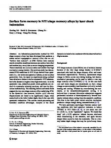
Fig. 6: Optical micrographs taken of the specimens sintered at 1173 K for 15 min. [32] test. The specimen loaded to about 4.4% at room temperature showed a residual strain of about 2.1%. The shape recovery strain was evaluated by measurement of the specimen length after heating up to 423 K, as being about 1.0%, which corresponds to 48% of the residual strain. Figure 8 shows the MFIS at 310 K and the M-T curves in a magnetic field of H = 0.05 and 7 T for the specimen sintered at 1173 K (in the inset), where the specimen for the MFIS was compressively pre-deformed at room temperature and the residual strain was 3.1%. The magnetic field was applied in
Materials Science Forum Vol. 635
29
the direction parallel to that for the compressive strain. In the M-T curves of the inset, the transformation behavior in the magnetic field of 7 T is basically the same as that of 0.05 T, except for the shifts of -20 K and -24 K in the Ms and Af temperatures, respectively. From these M-T curves, the MMSME is expected at temperatures between about 290 and 310 K. Actually, a MFIS of 0.56% was obtained at 310 K, where the induced strain steady appears in the magnetic field from 0 T to 8 T as shown in Fig. 8. Thus, the MMSME can be confirmed in the sintered polycrystalline specimen with the enhanced ductility, whereas the shape recovery rate for the residual strain is only 18%. This low value of the shape recovery was apparently brought about by the large transformation interval and the existence of the second phase.
Fig. 7: Compressive stress-strain curves at room temperature obtained from the specimen (SPS) sintered at 1173 K and from the conventional alloy (CA) specimen fabricated by induction melting followed by annealing at 1173 K for 24 h. The inset shows the magnified curves in the low stress region. [32]
Fig. 8: Magnetic field-induced shape recovery obtained at 310 K in the specimen sintered at 1173 K. Thermomagnetization curves at a magnetic field strength of H = 0.05 T and 7 T in the specimens sintered at 1173 K are shown in the inset. [32]
Concluding Remarks Since the MMSMA was reported, many investigations for the MMSMA have been performed and many unique physical properties, such as giant magnetoresistance, giant magnetothermal conductivity and inverse magnetocaloric effect, have been found. However, the basic magnetic properties have still not been sufficiently clarified, and there are many problems preventing practical use, such as the ductility and the huge magnetic field required to induce the reversible phase transformation. Through further basic and practical studies, progress will hopefully be made in understanding the physical properties of the metamagnetic shape memory alloys so as to allow practical applications.
30
Ferromagnetic Shape Memory Alloys II
Acknowledgement This study was supported by Grant-in-Aids from the Japanese Society for the Promotion of Science (JSPS), and by the Global COE Program, Tohoku University, MEXT, Japan. References [1] K. Ullakko, J. K. Huang, C. Kanter, V. V. Kokorin and R. C. O'Handley: Appl. Phys. Lett., Vol.69 (1996) p.1966. [2] A. Sozinov, A.A. Likhachev and K. Ullakko: IEEE Trans. Mab., Vol.38, (2002) p.2814. [3] M.A, Marioni, R.C. O’Handley, S.M. Allen, S.R. Hall, D.I. Paul, M.L. Richard, J. Feuchtwanger, B.W. Peterson, J.M. Chambers and R. Techapoesancharoenkij: J. Mag. Mag. Mater., Vol.290-291, (2005), p.35. [4] H.E.Karaca, I. Karaman, B. Basaran, Y.I. Chumlyakov and H.J. Maier: Acta Mater., Vol.54, (2006), p.233. [5] S.J. Jeong, K. Inoue, S. Inoue, K. Koterazawa, M. Taya and K. Inoue: Mater. Sci. Eng., Vol.A359, (2003), p.253. [6] I. Karaman, H.E. Karaca, B. Basaran, D.C. Lagoudas, Y.I. Chumlyakov and H.J. Maier: Scripta Mater., Vol.55, (2006), p.403. [7] H.E. Karaca, I. Karaman, B. Basaran, D.C. Lagoudas, Y.I. Chumlyakov and H.J. Maier: Acta Mater., Vol.55, (2007), p.4253. [8] P. J. Webster, K. R.A. Ziebeck, S. L. Town and M. S. Peak: Philos. Mag., Vol.B49, (1984), p.295. [9] R. Kainuma, H. Nakano and K. Ishida: Metall. Mater. Trans. A, Vol.27A, (1996), p.4153. [10] A. Fujita, K. Fukamichi, F. Gejima, R. Kainuma and K. Ishida, Appl. Phys. Lett., Vol.77, (2000), p.3054. [11] K. Oikawa, L. Wulff, T. Iijima, F. Gejima, T. Ohmori, A. Fujita, K. Fukamichi, R. Kainuma and K. Ishida: Appl. Phys. Lett., Vol.79, (2001), p.3290. [12] K. Oikawa, T. Ota, F. Gejima, T. Ohmori, R. Kainuma and K. Ishida: Mater. Trans., 42, (2001), p.2472. [13] M. Wuttig, J. Li and C. Craciunescu: Scripta Mater., Vol.44, (2001), p.2393. [14] K. Oikawa, T. Ota, T. Ohmori, Y. Tanaka, H. Morito, A. Fujita, R. Kainuma, K. Fukamichi and K. Ishida: Appl. Phys. Lett., Vol.81, (2002), p.5201. [15] H. Morito, K. Oikawa, A. Fujita, K. Fukamichi, R. Kainuma and K. Ishida: Scripta Mater., Vol.53,( 2005),p.1237. [16] Y. Sutou, Y. Imano, N. Koeda, T. Omori, R. Kainuma, K. Ishida and K. Oikawa: Appl. Phys. Lett., Vol.85, (2004), p.4358. [17] T. Krenke, E. Duman, M. Acet, E.F. Wassermann, X. Moya, L. Manosa and A. Planes: Nature Mater., Vol.4, (2005), p.450. [18] Z. D. Han, D. H. Wang, C. L. Zhang, S. L. Tang, B. X. Gu and Y. W. Du: Appl. Phys. Lett., Vol.89, (2006), p.182507. [19] K. Koyama, H. Okada, K. Watanabe, T. Kanomata, R. Kainuma, W. Ito, K. Oikawa and K. Ishida: Appl. Phys. Lett., Vol.89, (2006), p.182510. [20] V. K. Sharma, M. K. Chattopadhyay, K. H. B. Shaeb, Anil Chouhan and S. B. Roy: Appl. Phys. Lett., Vol.89, (2006), p.222509. [21] B. Zhang, X.X. Zhang, S.Y. Yu, J.L. Chen, Z.X. Cao and G.H. Wu: Appl. Phys. Lett., Vol.91, (2007), p.012510.
Materials Science Forum Vol. 635
31
[22] A. Planes, L. Manosa and M. Acet: J. Phys.: Cond. Matt., Vol. 21 (2005) p.233201. [23] T. Kanomata, K. Fukushima, H. Nishihara, R. Kainuma, W. Ito, K. Oikawa, K. Ishida , K. –U. Neumann and K.R.A. Ziebeck: Mater. Sci. Forum, Vol. 583, (2008) p. 119. [24] T. Kanomata, T. Yasuda, S. Sasaki, H. Nishihara, R. Kainuma, W. Ito, K. Oikawa, K. Ishida , K.–U. Neumann and K.R.A. Ziebeck: J. Magn. Magn. Mater., Vol. 321 (2009) p. 773. [25] P. J. Brown, A. P. Gandy, K. Ishida, R. Kainuma, T. Kanomata, K-U.Neumann, K. Oikawa, B. Ouladdiaf and K. R. A. Ziebeck: J. Phys. Condens. Matter, Vol.18 (2006) p. 2249 [26] T. Krenke, M. Acet, E.F. Wassermann, X. Moya, L. Mañosa and A.Planes: Phys. Rev. B Vol.72 (2005), p. 014412. [27] E. Şaşioğlu, L.M. Sandratskii and P. Bruno: Phys. Rev. B Vol. 71 (2005), p. 214412. [28] R.Y. Umetsu, R. Kainuma, Y. Amako, Y. Taniguchi, T. Kanomata, K. Fukushima, A. Fujita, K. Oikawa and K. Ishida: Appl. Phys. Lett., Vol. 93, (2008) p. 042509. [29] V. V. Khovaylo, T. Kanomata, T. Tanaka, M. Nakashima, Y. Amako, R. Kainuma, R. Y. Umetsu, H. Morito and H. Miki: to be submitted. [30] R. Kainuma, Y. Imano, W. Ito, Y. Sutou, H. Morito, S. Okamoto, O. Kitakami, K. Oikawa, A. Fujita, T. Kanomata and K. Ishida: Nature, Vol.439, (2006), p.957. [31] T. Sakon, S. Yamazaki, Y. Kodama, M. Motokawa, T. Kanomata, K. Oikawa, R. Kainuma and K. Ishida: Jpn. J. Appl. Phys., Vol.46 (2007) p.995. [32] K. Ito, W. Ito, R. Y. Umetsu, S.Tajima, H.Kawaura, R. Kainuma and K. Ishida: Scr. Mater., Vol.61 (2009) p.504 [33] R. Kainuma, Y. Imano, W. Ito, Y. Sutou, H. Morito, S. Okamoto, O. Kitakami, K. Oikawa, A. Fujita, T. Kanomata and K. Ishida: Appl. Phys. Lett., Vol.88, (2006), p.192513. [34] T. Miyamoto, M. Nagasako, R. Kainuma and K. Ishida: unpublished work
Ferromagnetic Shape Memory Alloys II 10.4028/www.scientific.net/MSF.635
NiMn-Based Metamagnetic Shape Memory Alloys 10.4028/www.scientific.net/MSF.635.23 DOI References [1] K. Ullakko, J. K. Huang, C. Kanter, V. V. Kokorin and R. C. O'Handley: Appl. Phys. Lett., Vol.69 (1996) p.1966. 10.1063/1.117637 [2] A. Sozinov, A.A. Likhachev and K. Ullakko: IEEE Trans. Mab., Vol.38, (2002) p.2814. 10.1109/TMAG.2002.803567 [3] M.A, Marioni, R.C. O’Handley, S.M. Allen, S.R. Hall, D.I. Paul, M.L. Richard, J. Feuchtwanger, B.W. Peterson, J.M. Chambers and R. Techapoesancharoenkij: J. Mag. Mag. Mater., Vol.290-291, (2005), p.35. 10.1016/j.jmmm.2004.11.156 [4] H.E.Karaca, I. Karaman, B. Basaran, Y.I. Chumlyakov and H.J. Maier: Acta Mater., Vol.54, (2006), p.233. 10.1016/j.actamat.2005.09.004 [5] S.J. Jeong, K. Inoue, S. Inoue, K. Koterazawa, M. Taya and K. Inoue: Mater. Sci. Eng., Vol.A359, (2003), p.253. 10.1016/S0921-5093(03)00359-9 [6] I. Karaman, H.E. Karaca, B. Basaran, D.C. Lagoudas, Y.I. Chumlyakov and H.J. Maier: Scripta Mater., Vol.55, (2006), p.403. 10.1016/j.scriptamat.2006.03.061 [7] H.E. Karaca, I. Karaman, B. Basaran, D.C. Lagoudas, Y.I. Chumlyakov and H.J. Maier: Acta Mater., Vol.55, (2007), p.4253. 10.1016/j.actamat.2007.03.025 [9] R. Kainuma, H. Nakano and K. Ishida: Metall. Mater. Trans. A, Vol.27A, (1996), p.4153. 10.1007/BF02595663 [10] A. Fujita, K. Fukamichi, F. Gejima, R. Kainuma and K. Ishida, Appl. Phys. Lett., Vol.77, (2000), p.3054. 10.1063/1.1323552 [11] K. Oikawa, L. Wulff, T. Iijima, F. Gejima, T. Ohmori, A. Fujita, K. Fukamichi, R. Kainuma and K. Ishida: Appl. Phys. Lett., Vol.79, (2001), p.3290. 10.1063/1.1418259 [12] K. Oikawa, T. Ota, F. Gejima, T. Ohmori, R. Kainuma and K. Ishida: Mater. Trans., 42, (2001), p.2472. 10.2320/matertrans.42.2472 [14] K. Oikawa, T. Ota, T. Ohmori, Y. Tanaka, H. Morito, A. Fujita, R. Kainuma, K. Fukamichi and K. Ishida: Appl. Phys. Lett., Vol.81, (2002), p.5201. 10.1063/1.1532105 [15] H. Morito, K. Oikawa, A. Fujita, K. Fukamichi, R. Kainuma and K. Ishida: Scripta Mater., Vol.53, (2005),p.1237. 10.1016/j.scriptamat.2005.08.009 [16] Y. Sutou, Y. Imano, N. Koeda, T. Omori, R. Kainuma, K. Ishida and K. Oikawa: Appl. Phys. Lett., Vol.85, (2004), p.4358.
10.1063/1.1808879 [17] T. Krenke, E. Duman, M. Acet, E.F. Wassermann, X. Moya, L. Manosa and A. Planes: Nature Mater., Vol.4, (2005), p.450. 10.1038/nmat1395 [18] Z. D. Han, D. H. Wang, C. L. Zhang, S. L. Tang, B. X. Gu and Y. W. Du: Appl. Phys. Lett., Vol.89, (2006), p.182507. 10.1063/1.2385147 [19] K. Koyama, H. Okada, K. Watanabe, T. Kanomata, R. Kainuma, W. Ito, K. Oikawa and K. Ishida: Appl. Phys. Lett., Vol.89, (2006), p.182510. 10.1063/1.2374868 [20] V. K. Sharma, M. K. Chattopadhyay, K. H. B. Shaeb, Anil Chouhan and S. B. Roy: Appl. Phys. Lett., Vol.89, (2006), p.222509. 10.1063/1.2399365 [21] B. Zhang, X.X. Zhang, S.Y. Yu, J.L. Chen, Z.X. Cao and G.H. Wu: Appl. Phys. Lett., Vol.91, (2007), p.012510. 10.1063/1.2753710 [23] T. Kanomata, K. Fukushima, H. Nishihara, R. Kainuma, W. Ito, K. Oikawa, K. Ishida, K. –U. Neumann and K.R.A. Ziebeck: Mater. Sci. Forum, Vol. 583, (2008) p. 119. 10.4028/www.scientific.net/MSF.583.119 [24] T. Kanomata, T. Yasuda, S. Sasaki, H. Nishihara, R. Kainuma, W. Ito, K. Oikawa, K. Ishida, K.–U. Neumann and K.R.A. Ziebeck: J. Magn. Magn. Mater., Vol. 321 (2009) p. 773. 10.1016/j.jmmm.2008.11.079 [25] P. J. Brown, A. P. Gandy, K. Ishida, R. Kainuma, T. Kanomata, K-U.Neumann, K. Oikawa, B. Ouladdiaf and K. R. A. Ziebeck: J. Phys. Condens. Matter, Vol.18 (2006) p. 2249 10.1088/0953-8984/18/7/012 [26] T. Krenke, M. Acet, E.F. Wassermann, X. Moya, L. Mañosa and A.Planes: Phys. Rev. B Vol.72 (2005), p. 014412. 10.1103/PhysRevB.72.014412 [28] R.Y. Umetsu, R. Kainuma, Y. Amako, Y. Taniguchi, T. Kanomata, K. Fukushima, A. Fujita, K. Oikawa and K. Ishida: Appl. Phys. Lett., Vol. 93, (2008) p. 042509. 10.1063/1.2960551 [30] R. Kainuma, Y. Imano, W. Ito, Y. Sutou, H. Morito, S. Okamoto, O. Kitakami, K. Oikawa, A. Fujita, T. Kanomata and K. Ishida: Nature, Vol.439, (2006), p.957. 10.1038/nature04493 [31] T. Sakon, S. Yamazaki, Y. Kodama, M. Motokawa, T. Kanomata, K. Oikawa, R. Kainuma and K. Ishida: Jpn. J. Appl. Phys., Vol.46 (2007) p.995. 10.1143/JJAP.46.995 [32] K. Ito, W. Ito, R. Y. Umetsu, S.Tajima, H.Kawaura, R. Kainuma and K. Ishida: Scr. Mater., Vol.61 (2009) p.504 10.1016/j.scriptamat.2009.05.008 [33] R. Kainuma, Y. Imano, W. Ito, Y. Sutou, H. Morito, S. Okamoto, O. Kitakami, K. Oikawa, A. Fujita, T. Kanomata and K. Ishida: Appl. Phys. Lett., Vol.88, (2006), p.192513. 10.1063/1.2203211