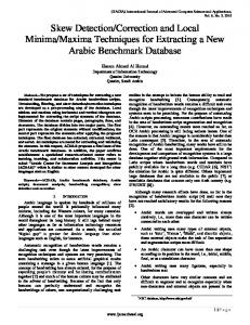
Fig 5.11 the Input and output referred noise voltage power spectral density ... Figure 6.11 The layout of the AFFDNR Based Feedback Network Cascade Filterâ¦
Noise-Shaping Gain-Filtering Techniques For Wireless Applications
University Of Sharjah Department of Electrical and Computer Engineering Senior Design Project (II) Fall 2012/2013
Done By
Aisha Abdallah U00010746
Sara Khalid U00013269
Supervisor: Dr. Soliman A. Mahmoud Examiner: Dr. Ahmed El Wakil Chair: Dr. Bassel Soudan
Table of Contents Chapter 1
Introduction………………………………………..……………………..….1
1.1 1.2 1.3 Chapter 2
Historical Background………………………………..…………….……..…1 Objective………………….……………………………..………….…..……3 Thesis Organization…………..…………………………………….…..……3 Mobile T.V. Standards and Receiver Architectures………………...….……4
2.1
Introduction……………………………………………………….….….…..4
2.2
Receivers Key Design…………….…...………………………….…….…...4
2.3
Receiver Architecture…………………………………………………........10
2.4
Mobile T.V. …………………………………………………………….….17
2.5
Low Noise Mobile T.V. Receiver………………………………………..…19
Chapter 3
Elliptical Filter Standards Responses……………………………................24
3.1
Introduction…………………………………………………………….......24
3.2
Butterworth Filters……………………………………………………….....24
3.3 3.4 3.5 Chapter 4
Chebyshev Filters..…………….……………..…………………...……..….28 Bessel Filters.……………………………..…………………………….…..32 Elliptic Filters ……………………………………………………………....35 Design Parameters of CMOS Op Amp.…………………………...............….42
4.1
Introduction……………………………………..……..…………………...42
4.2
The Basic Two-Stage CMOS Op Amp Design Parameters………………..42
4.3
Design Steps………………………………………………………………..49
4.4
The proposed CMOS op amp……………………………………….……...55
4.5
The simulated results of CMOS op amp…………………………….….….55
ii
Chapter 5
Third Order Noise Shaped Elliptic Filter and AFFDNR Gain Filtering Stages………..……………………..………………………..….…64
5.1
Introduction…………………………………………………………….…...64
5.2
The Realization of Grounded FDNR ………………………………....….....64
5.3
FDNR Based Filter……………………………………………………….....65
5.4
AFFDNR Based Feedback Network……………………………………….73
5.5
The simulation results………………………………………………………73
Chapter 6
Filter Layout Design……………………...…………………………..…........80
6.1
Introduction ……………….……………..…………………………………80
6.2
Op amp Layout …………………………………………………….............81
6.3
FDNR Based Filter and AFFDNR Based Feedback Network cascade filter Layout ……………………………………………………………………....81
Chapter 7
Conclusion………….……...………………..……………………………....93
7.1
Summary……………….……………..…………………………………….93
7.2
Related Issues……………………………………………………..…..........93
References……………………………………………………………..………………..….94 Appendixes …………………………………………………………………...…………....96
iii
Acknowledgment
This project has been taken robust efforts and stable steps. The completeness of the project is done first by means of Allah, the provider for us confidence and strength to finalize this work. Secondly, we would like to acknowledge some individuals for their help, advice supplying information and tremendous efforts. We would like to express our highest sincere sense of appreciation to our supervisor Prof. Dr. Soliman Mahmoud for his patient guidance, encouragement and excellent advice throughout this work. Also, the express of our gratitude extend towards our examiner; Prof. Dr. Ahmed El-Wakil, and our chair; Dr. Bassel Soudan for their kind recommendation and co-operation which help us to complete this project. Our acknowledgements also send to our colleagues; Ahmed Ba-Makhramah and Saeed Ali Altuinje for their assistances in developing the project and providing us with essential programs. Finally, we would like to express our special and deep thankfulness to our families for their continuous support, understanding and infinite love, through the duration of this project.
vi
Abstract
Typical gain-filtering techniques have already been used popularly in wireless application; however, many fundamental issues of such techniques, such as reducing the noise on account of power and area, have generated obstacles on these techniques. This project will study the noise-shaping gain-filtering techniques that can be one of the successful ways in which minimizing the noise over the range of the passband of the filter is the proposed aim. These techniques will be demonstrated by applying it on a part of CMOS mobile-TV tuner at integrated receiver. This project mainly focuses on designing a low pass filter which consists of two parts. The first part is Frequency Dependent Negative Resistance (FDNR) based third-order noise shaped pre-filter section as the mixer load, which has dc gain of 80dB , with cutoff frequency of 819MHz and input referred noise voltage power spectral density of 5.1058nV/sqrt(Hz). The second part is Asymmetric Floating Frequency Dependent Negative Resistance (AFFDNR) based feedback network which is a part of amplifier instrumentation topology, which has dc gain of 20dB, with cutoff frequency of 4.6MHz and input referred noise voltage power spectral density of 55.64nV/sqrt(Hz). These two filters depend on CMOS op amp which has dc gain of 81.849 dB, with unity gain bandwidth of 319.202 MHz, phase margin of 61.o and power dissipation of 428.431μWatt. This CMOS op amp is designed based on 0.25-μm CMOS technology with power supply of
1.5V.
vi
مهخص انزسانح انرمنْاخ انمعرادج فِ عمهْح انرضخْم-انرزشْخ داسخ عهَ شعثْح كثْزج فِ اسرخذاميا فِ انرطثْماخ انالسهكْح؛ ً ،نكن انعذّذ من انمضاّا األساسْح فِ ىذه انرمنْاخ ،مثم انذذ من انضٌضاء عهَ دساب انطالح ًانمسادح ،خهمد عمثاخ عهَ ىذه انرمنْاخ. ىذا انمشزًع سْذرص ذمنْاخ ذشكْم انضٌضاء انرضخْم-انرزشْخ ( noise-shaping gain-filtering ً ،)techniquesانرِ ذعرثز إدذٍ انطزق انرِ نجذد انرمهْم من انضجْج عهَ مذٍ
passbandانمزشخً ،ىٌ
انيذف انممرزح .سْرم عزض ىذه انرمنْاخ عن طزّك ذطثْمو عهَ جشء من دائزج انرزشْخ نمٌانف انرهفاس انمذمٌل فِ دائزج CMOSاالسرمثال انمراكمهح .ىذا انمشزًع ّزكش أساسا عهَ ذصمْم مزشخ انرزدداخ انمنخفضح ًانذُ ّرأنف من جشأّن. انجشء األًل ىٌ انمماًمح انسهثْح انمعرمذج عهَ انرزدد ( )FDNRانمائمح عهَ درجح-ثانثح ما لثم انرصفْح فِ مزدهح انخالط ّعمم كذمم نهخالط (ً ،)mixerانرِ نيا كسة انرْار انمسرمز ،08dBمع ذزدد انمطع ً ،018MHzمذخالخ مزجع جيذ انضٌضاء نهكثافح انمذرج انطْفْح ) . ..18.0nV/sqrt(Hzانجشء انثانِ ىٌ مماًمح سهثْح غْز انمرماثهح معرمذج عهَ انرزدد ( )AFFDNRانمائمح عهَ شثكح انمزذذج انرِ ىِ جشء من طٌتٌنٌجْا مضخم األجيشج ،انرِ نذّيا كسة انرْار انمسرمز ،08dBمع ذزدد انمطع ً 6.4MHzمذخالخ مزجع جيذ انضٌضاء نهكثافح انمذرج انطْفْح ( . ...46nV/sqrt)Hzىذه انمزشذاخ ذعرمذ عهَ CMOS op ampانذُ نذّو كسة انرْار انمسرمز ،81.849dBمع ًدذج عزض اننطاق انرزددُ ً ،319.202MHzداشْح انشاًّح تـ ً ،61.oذشرد فِ انطالح تممذار .428.431μWattىذا CMOS op ampصمم عهَ أساص ذكنٌنٌجْا 0.25-μm CMOSمع مصذر نهطالح تممذار
v
1.5فٌند.
List of Figures Fig. 1.1 Noise-shaping concept [1]………………………………...……………........................2 Fig. 2.1 Receiver Block Scheme…………………………………………………………..........12 Fig. 2.2 Super-heterodyne Receiver Architecture………...………………..…….…….…........12 Fig. 2.3 Zero-IF receiver Architecture………………………………………....….....................12 Fig. 2.4 Low-IF Receiver Architecture with I and Q Channel………..………….….….…......14 Fig. 2.5 Low-IF receiver with FM modulator……………………………………..…...…........14 Fig. 2.6 Low-IF Receiver Architecture with Digital Demodulator……………….….…….......14 Fig. 2.7 Zero-IF/Low-IF for Multi-standard Receiver…………………………….…………...15 Fig. 2.8Wide-band Double IF Receiver Architecture.................................................................15 Fig. 2.9 Digital-IF Sampling Receiver……………...……………………………….….............15 Fig. 2.10 Noise generating elements in a second order Sallen-Key Biquad [1]…...……...........22 Fig. 2.11 simplified block diagram of mobile T.V. receiver [1]……...…………………...........23 Fig. 3.1 Magnitude bode plot for the third order butterworth filter………………….…… ......26 Fig.3.2 Magnitude bode plots for the different order butterworth filter………….……............26 Fig. 3.3 Group delay plots for the different order butterworth filter ………………..…............27 Fig. 3.4 Magnitude bode plot for the third order chebyshev filter…………………...…............30 Fig. 3.5 Magnitude bode plots for the third order chebyshev filter……..……………................30 Fig. 3.6 Group delay plots for the different order chebyshev filter …………………..…...........31 Fig. 3.7 Magnitude bode plot for the third order bessel filter………………………….. ............33 Fig. 3.8 Magnitude bode plots for the third order bessel filter ………………............….............33 Fig.3.9 Group delay plots for the different order bessel filter…………………….......…....34
iv
Fig. 3.10 Magnitude bode plot for the third order elliptic filter………………………...........36 Fig. 3.11 Magnitude bode plots for the different order elliptic filter…………….…..............36 Fig. 3.12 Group delay plot for the elliptic different order filter………………………….......37 Fig. 3.13 A lowpass elliptic filter response…………………………………………...............39 Fig. 4.1The basic block diagram of the op amp stage with the secondary circuits [16] …......44 Fig. 4.2 The basic two-stage CMOS op-amp [20]..…………………………………………..44 Fig. 4.3 The small signal model of the miller op amp [20]……………………….....………..45 Fig. 4.4 Op amp as a buffer [22].................................................................................…….......45 Fig. 4.5 Two-stage miller op amp……………………………………………………..............51 Fig. 4.6 Simulation result for CC=2.5pF to find Ao and fu…………………………………...53 Fig. 4.7 Simulation result for CC=2.5pF to find φM……………………….…………….........53 Fig. 4.8 Simulation result for CC=2.5pF to find input referred noise………………………....54 Fig. 4.9The frequency response for CC=2.5pF to find input referred noise……………..........54 Fig. 4.10The schematic of CMOS op amp [1] ……………………………………………......57 Fig 4.11The frequency response of the CMOS op amp shows the DC gain………………......60 Fig 4.12The frequency response shows the unity gain bandwidth………………………........60 Fig 4.13The phase voltage of the CMOS op amp………………………………………….......61 Fig 4.14Power consumption……………………………………………………………………61 Fig 4.15 (a) Op-amp based buffer, (b) The input and the output waveform………………......62 Fig 4.16 (a) Op-amp based integrator, (b) The input and the output waveform…………...…..63 Fig. 5.1 GIC network……………………………………………………………………..........66 Fig. 5.2 The equivalent circuit of grounded FDNR and its symbol………...……….................66 Fig. 5.3The third-order elliptic circuit after the mixer output [1]……………………………...67 Fig. 5.4 The transfer function of low pass signal, (b) The transfer function with ripples……...70
iiv
Fig. 5.5 Noise transfer function of OPA1…………………………………………………......71 Fig. 5.6 Noise transfer function of OPA2………………………………………………..........71 Fig. 5.7 Noise transfer function of RZ ………………………………………………….……..72 Fig. 5.8 Noise transfer function of R1……………………………………………………........72 Fig. 5.9 AFFDNR with feedback network [2]……………………………………………........74 Fig 5.10The frequency response of FDNR………………………………………………........77 Fig 5.11 the Input and output referred noise voltage power spectral density (FDNR)………..77 Fig 5.12The frequency response of AFDNR……………………………………………….....78 Fig 5.13 different The frequency response of AFDNR bandwidth……………………….......78 Fig 5.14 the Input and output referred noise voltage power spectral density(AFFDNR)…….79 Figure 6.1 The layout of the resistor by using L-edit software…………………………..........81 Figure 6.2 The layout of the capacitor by using L-edit software……………………………...81 Figure 6.3 The layout of the proposed op-amp………………………………………………...82 Figure 6.4 The frequency response of the extracted CMOS op-amp shows the DC gain, unity gain bandwidth and the phase margin ………………………………………………………....83 Fig 6.5 Power consumption of the extracted CMOS op amp………………………………….84 Fig 6.6 (a) Op-amp based buffer, (b) The input and the output waveform……………………84 Fig 6.7 (a)Op-amp based integrator, (b) The input and the output waveform…………………85 Figure 6.8 The layout of the FDNR Based Filter………………………………………………87 Figure 6.9 The frequency response of the extracted FDNR Based Filter ……………………..88 Fig 6.10The input and output referred noise voltage power spectral density of FDNR……….89 Figure 6.11 The layout of the AFFDNR Based Feedback Network Cascade Filter……….......90
iiiv
Figure 6.12 The frequency response of the extracted AFDNR Based Feedback Network Cascade Filter……………………………………………………………………………………………...91 Fig 6.13The input and output referred noise voltage power spectral density of AFDNR Based Feedback Network Cascade Filter ………………………………………………………………92
iiiv
List of Tables Table 3.1 The comparison between all filters…………………………………………...41 Table 4.1 Process parameters table……………………………………………………...51 Table 4.2 Specifications of CMOS op amp table………………………………………..52 Table 4.3 Design parameters for the single ended op amp……………………………...52 Table 4.4 Simulation results for CC=2.5pF………………………...…………………...52 Table 4.5 Structure parameters in the folded-cascode input stage………………………58 Table 4.6 A comparison among the three different types of output classes……………..58 Table 4.7 CMOS opamp specifications………………………………………………….58 Table 4.8 Design parameters for the CMOS op amp…………………………………....59 Table 4.9 CMOS opamp specifications………………………………………………….59 Table 5.1 FDNR specifications………………………………………………………….75 Table 5.2 FDNR specifications……………………………………………………….…75 Table 5.3 AFFDNR specifications………………………………………………………76 Table 5.4 AFFDNR specifications………………………………………………………76 Table 6.1 Extracted CMOS opamp specifications after simulation……………………...83 Table 6.2 Extracted FDNR Based Filter specifications after simulation………………..88 Table 6.3 AFFDNR Based Feedback Network Cascade Filter specifications…………..91
xi
List of Terms ADC
Analog to Digital Converter
AFFDNR
Asymmetric Floating Frequency Dependent Negative Resistance
CMOS
Complementary Metal Oxide Semiconductor
DMB-T
Digital Multimedia Broadcast-Terrestrial
DQPSK
Differential Quadrature Phase Shift Keying
DR
Dynamic range
DVB-H
Digital Video Broadcasting-Handheld
DVB-T
Digital Video Broadcasting-Terrestrial
FDNR
Frequency Dependent Negative Resistance
FEC
Forward Error Detection
GFSK
Gaussian Frequency Shift Keying
GIC
Generalized Impedance Converter
GMSK
Gaussian Minimum Shift Keying
IC
Integrated Circuit
ICMR
Input Common Mode Ratio
ID3
Third-order inter-modulation Distortion
IF
Intermediate Frequency
IIP3
Input-referred IP3
IP3
Third-order Intercept Point
IR
Image Rejection
ISDB-T
Integrated Services Digital Broadcasting-Terrestrial
LNA
Low-Noise Amplifier xii
MOSFET
Metal Oxide Semiconductor Field Effect Transistor
MPE-FEC
Multi Protocol Encapsulated-Forward Error Correction
NF
Noise Figure
PMA
Post-Mixer Amplifier
PSRR
Power Supply Rejection Ratio
OFDM
Orthogonal Frequency Division Multiplex
OIP3
Output-referred IP3
Op Amp
Operational Amplifier
QAM
Quadrature Amplitude Modulation
QPSK
Quadrature Phase Shift Keying
RF
Radio Frequency
SFDR
Spurious-Free Dynamic Range
SFN
Single Frequency Network
xiii
List of Symbols Symbol
Name
Unit
Symbol
R
Resistor
Ohm
Ω
C
Capacitor
Farad
F
L
Inductor
Henry
H
Z
Impedance
Ohm
Ω
V
Voltage
Volt
V
I
Current
Ampere
A
Frequency
radian per second
rad/s
Threshold voltage
Volt
V
Conduction parameter
milliAmpere/volt squared
mA/
Oxide capacitance per unit area Farad/unit area
F/
=A.s/ ./
Mobility of the electrons
Unit area/Joule/Ampere
W
Width
Unit length
μm
L
Length
Unit length
μm
W/L
Aspect ratio
Unit less
unit less
Transconductance
milliAmpere/volt
mA/V
SR
Slew rate
Volt per microsecond
V/μs
Ao
DC gain
Decibel
dB
ƒu
Unity-gain frequency
megaHertz
MHz
φM
Phase margin
Degree
deg
xiv
/V.s