Av. Carl Friedrich Gauss 7, 08860 Castelldefels, Spain. David Declercq. ETIS, ENSEA, University of Cergy-Pontoise, CNRS. F-95000, Cergy-Pontoise, France.
Non-Binary Coding for Vector Channels Stephan Pfletschinger
David Declercq
Centre Tecnològic de Telecomunicacions de Catalunya Av. Carl Friedrich Gauss 7, 08860 Castelldefels, Spain
ETIS, ENSEA, University of Cergy-Pontoise, CNRS F-95000, Cergy-Pontoise, France
Abstract—We consider the application of non-binary coding schemes to vector channels, in particular we apply 𝑞-ary LDPC codes to multiple-antenna transmission schemes. Based on the principle of providing a good equivalent channel to the coding scheme, we directly map the code symbols to the transmit signal and find some suitable multi-dimensional mappings. The performance is assessed by simulations and we find that non-binary coding with direct mapping provides a significant advantage over its binary counterpart and over some space-time diversity schemes.
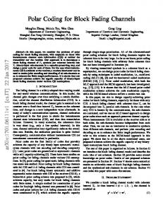
I. I NTRODUCTION Modern communication systems frequently include multiple transmit antennas while channel coding, being one of the enabling technologies for wireless transmission, is an indispensable ingredient. In recent years, non-binary LDPC codes have gained importance in the field of modern channel coding and have shown excellent performance [1], [2]. Despite the huge body of literature dealing with MIMO systems, relatively few effort has been dedicated to the joint design of multipleantenna schemes with non-binary coding (see e.g. [3], [4], [5], [6]). Recently, we found a significant performance gain of nonbinary LDPC codes for certain MIMO configurations, with respect to binary coding schemes [7]. In this paper, we extend our previous work to include a wider range of transmit parameters and outline the design principles to combine a nonbinary coding scheme with a vector channel. This approach is based on multi-dimensional mappings which allow to combine 𝑞-ary coding with any desired number of transmit antennas. Although we focus on LDPC codes, the presented principles apply to any 𝑞-ary codes with soft decoding. II. P ROBLEM S TATEMENT AND S YSTEM M ODEL We consider the transmission of signals x ∈ ℂ𝑛T ×𝑇 over a MIMO channel H ∈ ℂ𝑛R ×𝑛T with 𝑛T transmit and 𝑛R receive antennas, and 𝑇 channel uses, assuming that the transmitter has no channel state information while the receiver knows the channel perfectly. For simplicity, we assume that the components of H are i.i.d. Rayleigh fading. A. The Equivalent Channel Our objective is to find a space-time scheme which connects the channel coding scheme to the MIMO channel, as depicted in Fig. 1, and provides a high rate at low error probability. More precisely, the optimization criteria is rate maximization ˆ ]. subject to a given word error probability 𝑃w = 𝑃 [u ∕= u Since an exact joint optimization of the overall system is out
������ ���� ����
���� ��� � ∈ ��� ���� � ∈ ��� �� ���
�� �∈ � ������� μ
�
� ∈ ��� � ������ �������
� ∈ � � ���� �� ���
�� ∈ ���
���
Figure 1.
Block diagram for a vector channel with 𝑞-ary channel coding
of reach, we select the space-time scheme according to the following guidelines: 1) The performance of LDPC (or turbo) codes depends nearly exclusively on the capacity of the equivalent channel between encoder and decoder (see Fig. 1). This observation has been reported by several authors [8], [9], [10] and has been applied e.g. for the design of bit-loading schemes or for physical-layer-abstraction in system level simulations [11]. 2) The equivalent channel shall be memoryless since this is assumed by a belief propagation decoder. The selection of the space-time “code” hence follows the approach advocated by J. Massey [12] to separate modulation and coding such that the modulation scheme provides an equivalent channel of high capacity to the coding scheme. For a modern channel code with a soft-input decoder, this equivalent channel is discrete-input continuous-output. As an additional requirement, the soft demapper shall be of low or moderate complexity in order to be implementable with reasonable complexity. B. Non-Binary LDPC Codes Non-binary LDPC codes offer some intrinsic benefits compared to their binary counterparts, especially in the practically important case of short to medium block lengths and high spectral efficiency [1], [2], [13]. In the following, we will use the four 𝑞-ary LDPC codes specified in Table I as a running example. The encoder takes a message u consisting of 𝐾 𝑞ary GF (Galois field) symbols and encodes it into a codeword c of 𝑁 code symbols, hence the code rate is 𝑅c = 𝐾 𝑁 . At the receiver, the decoder input is formed by L-vectors defined by T L𝑖 = [𝐿𝑖,0 , 𝐿𝑖,1 , . . . , 𝐿𝑖,𝑞−1 ] with components 𝐿𝑖,𝑘 ≜ ln
𝑃 [𝑐𝑖 = 𝛼𝑘 ∣y] , 𝑘 = 0, 1, . . . , 𝑞 − 1 𝑃 [𝑐𝑖 = 𝛼0 ∣y]
(1)
and 𝛼0 , 𝛼1 , . . . , 𝛼𝑞−1 denote the elements of the Galois field 𝔽𝑞 . Each L-vector corresponds to one code symbol and con-
12th IEEE International Workshop on Signal Processing Advances in Wireless Communication (SPAWC) San Francisco, 26-29 June 2011
stitutes a sufficient statistic of the received signal, provided the channel is memoryless. Note that the codeword length in bits is given by 𝑁bin = 𝑁 ⋅ log2 𝑞, hence codes A, C and D have the same length when viewed as binary codes. Table I PARAMETERS (GF ORDER 𝑞, WORD LENGTH 𝑁 , CODE RATE 𝑅c ) OF EXEMPLARY LDPC CODES
code code code code
A B C D
𝑞 64 64 64 256
𝑁 480 10752 480 360
𝑅c = 𝐾/𝑁 1/2 1/2 3/4 1/2
𝑁bin 2880 64512 2880 2880
many typical values of 𝑛T , 𝑞 and 𝑇 , this condition results in a non-integer value for 𝑀 and hence no suitable twodimensional constellation exists for these cases. B. Multidimensional Mappings The limitations of standard SM can be overcome easily by considering a direct mapping from the 𝑞-ary code symbol to the 𝑛T × 𝑇 transmit matrix: 𝝁 : 𝔽𝑞 → 퓧 ⊂ ℂ𝑛T ×𝑇 ,
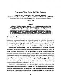
The word error rate of codes A, B and C combined with QAM over an AWGN or Rayleigh fading channel is depicted in Fig. 2 as a function of the mutual information per coded bit, which is equivalent to the capacity of the equivalent channel. The performance of code D (not shown in Fig. 2) is very similar to that of code A, which is not surprising since they share the code rate and the binary length. The decoder uses FFT-based belief propagation [14] and a maximum of 100 iterations. We can observe that the word error rate indeed depends mainly on the capacity of the equivalent channel and to a much smaller extent on the type of this channel.
∣퓧 ∣ = 𝑞
(2)
This approach includes spatial multiplexing with twodimensional constellations as a special case but imposes no restrictions upon the number of transmit antennas or the GF order. The information bit rate of this scheme, given in bits per channel use (equivalent to bit/s/Hz), is 𝑅=
𝑅c log2 𝑞 𝑇
(3)
and hence the spectral efficiency is limited by 𝑇1 log2 𝑞, which is the reason why in the following we focus our attention on the case 𝑇 = 1. On the other hand, the case 𝑇 > 1 is a straightforward extension and is indicated for low SNR.
0
10
C. Soft Demapping
Code C: N = 480 R = 3/4
−1
10
c
code A: N = 480 R = 1/2
−2
WER
10
−3
10
c
code B: N = 10752 R = 1/2
QPSK 8−QAM 16−QAM 64−QAM
c
−4
10
continuous lines, filled markers: AWGN dotted lines, empty markers: Rayleigh −5
10
0.5
0.55
0.6 0.65 0.7 0.75 mutual information per coded bit I
0.8
0.85
c
Figure 2. Word error rates of codes A, B, C as a function of the mutual information per coded bit over the AWGN and the fast Rayleigh fading channel
III. S PACE -T IME M APPING AND D EMAPPING In order to obtain a memoryless equivalent channel, each code symbol 𝑐𝑖 ∈ 𝔽𝑞 has to be mapped to an integer number 𝑇 of transmit vectors, i.e. channel uses. The obvious and simplest approach is to apply spatial multiplexing: A. Spatial Multiplexing with 2-dimensional Constellations Standard spatial multiplexing (SM) transmits at each antenna a complex-valued signal taken out of a constellation 𝒳 ′ ⊂ ℂ with 𝑀 = ∣𝒳 ′ ∣ signal points. For a bijective mapping between code symbols 𝑐 ∈ 𝔽𝑞 and transmit matrices [x1 , x2 , . . . , x𝑇 ], it must hold 𝑀 𝑛T 𝑇 = 𝑞 and hence we transmit 𝑛T 𝑇 ⋅ log2 𝑀 = log2 𝑞 bits per 𝑇 channel uses. For
For 𝑇 = 1, a code symbol 𝑐 ∈ 𝔽𝑞 = {𝛼0 , 𝛼1 , . . . , 𝛼𝑞−1 } is mapped onto an 𝑛T -dim transmit vector x ∈ 퓧 = {a0 , a1 , . . . , a𝑞−1 } and we define 𝝁(𝛼𝑘 ) = a𝑘 . We focus on this particular labeling, because when the cardinality of the memoryless vector channel matches the order of the Galois field, then the decoding performance has an inherent robustness to the different possible labelings in the signal space. As a matter of fact, even if the channel is not symbolwise symmetric, it can be shown that the density evolution thresholds of a family of non-binary LDPC codes do not depend on the chosen labeling, as long as the non-zero values of codes are chosen at random uniformly in {𝛼1 , . . . , 𝛼𝑞 } [15]. As a result, one can choose an arbitrary labeling of the signal points without noticeable difference of the WER performance. The received signal is given by y = Hx + w with w ∼ 𝒞𝒩 (0, 𝑁0 I). The corresponding L-vector is defined by (1) and since each received vector y corresponds to exactly one code symbol, its computation involves no marginalization and is given by 𝐿𝑘 = −
) 1 ( 2 2 ∣y − Ha𝑘 ∣ − ∣y − Ha0 ∣ 𝑁0
(4)
For a decoder, which is invariant to additive constants, we 2 can drop the second term and use 𝐿′𝑘 = − 𝑁10 ∣y − Ha𝑘 ∣ . Note that there is no requirement on the number of receive antennas; in particular, the case 𝑛R < 𝑛T is naturally included in the formulation.
IV. MIMO C APACITIES AND T HEIR E FFICIENT C OMPUTATION The ergodic channel capacity of an 𝑛T ×𝑛R MIMO channel is given by ( [ )] SNR ℋ HH 𝐶G = 𝔼 log2 det I𝑛R + (5) H 𝑛T This expression holds for Gaussian transmit signals, while for transmit signals taken out of a discrete alphabet 퓧 ,we have [16] ∑ [ ] 𝑝 (y∣z, H) (6) 𝐶CM = log2 𝑞 − 𝔼 log2 z∈퓧 x,y,H 𝑝 (y∣x, H) This capacity, which is known as coded modulation (CM) or input-constrained capacity is limited by log2 𝑞 and can be computed numerically by averaging over the fading and the noise according to the above expression. However, a more convenient way to compute this capacity is by information averaging, as described in [17] for EXIT charts, [𝑞−1 ] ∑ 𝑝𝑘 log2 𝑝𝑘 (7) 𝐶CM = log2 𝑞 + 𝔼 𝑘=0
where 𝑝𝑘 ≜ 𝑃 [x = a𝑘 ∣y] = 𝑃 [𝑐 = 𝛼𝑘 ∣y] is the a posteriori probability (APP) of the code symbol 𝑐 = 𝛼𝑘 . With the Lvectors, which are computed by the soft demapper, we have [𝑞−1 ] ∑ ′ 1 𝐿𝑘 ′ 𝔼 𝑒 (𝐿𝑘 − 𝛽) (8) 𝐶CM = log2 𝑞 + 𝛽 ln 2 𝑘=0
∑𝑞−1
′ 𝑘=0 exp(𝐿𝑘 ).
This second method of computation with 𝛽 ≜ is more convenient in our case since the L-values according to (4) are available from the soft demapper and their computation is simple. As a reference, we will also invoke the capacity 𝐶BICM for BICM (bit-interleaved coded modulation), which is defined and computed in [16] and for which holds 𝐶BICM ≤ 𝐶CM . V. D ESIGN OF M ULTI D IMENSIONAL M APPINGS The multidimensional constellation 퓧 has to be designed such that the capacity (6) is maximized, formally: max
{a0 ,...,a𝑞−1 }
𝐶CM ,
s.t.
𝑞−1 1 ∑ ∣a𝑖 ∣2 = 𝐸S 𝑛T 𝑖=0
Unfortunately, this optimization problem is non-convex in general, because the capacity 𝐶CM is not a concave function of the multidimensional constellation 퓧 [18]. This implies that there are no general-purpose efficient methods to numerically compute the multidimensional constellation that maximizes the capacity 𝐶CM and, thus, we resort to a heuristic approach: we have to place 𝑞 points in 2𝑛T real dimensions (for an 𝑛T dimensional complex-valued transmit vector) such that their distances are maximized. This is still a difficult problem, if we want to find the optimum solution, but we can obtain very good approximations with the following intuitive approaches: 1) Select the 𝑞 points from a sphere-packing lattice.
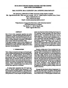
2) Select the 𝑞 points from the 2𝑛T -dim hypercube, if 𝑞 ≤ 22𝑛T . 3) Derive the constellation from a regular polytope. The resulting multi-dimensional mappings provide a rather modest gain with respect to the standard QAM constellations, as we will see below. Their main feature, however, is that they allow to combine any field size 𝑞 with any number of transmit antennas 𝑛T and channel uses 𝑇 , which is otherwise not possible. In the following, we will give examples for different numbers of antennas 𝑛T ∈ {2, 3, 4} and field orders 𝑞 ∈ {64, 256} involving all three methods. A. Two transmit antennas With two transmit antennas and 𝑞 = 64 or 𝑞 = 256, we can apply standard spatial multiplexing with 8-QAM and 16-QAM, respectively. Another possibility is to select the constellation from a sphere packing (SP), an idea which appeared in very similar contexts in e.g. [19], [4]. For four real dimensions, the packing 𝐷4 is the densest lattice packing [20]. From the tables given in [20], we know that there are 24 spheres at distance 1 from the origin, 24 spheres at distance 2, 96 spheres at distance 3, etc. To select 64 points, we thus consider the shells of spheres up to distance 3, including the origin, which results in 145 points. Out of these, we select 64 by excluding one-by-one the point which yields the worst distance metric. For 𝑞 = 256 points we have to consider spheres up to distance 5 from the origin. Finally, the constellation is shifted and normalized to obtain zero mean and power 𝑛T 𝐸S . The capacities for the 2 × 2 channel are drawn in Fig. 3. We can observe that the SP constellations achieve a slightly higher capacity than {8, 16}-QAM. On the other hand, we also see that there is not much margin for further improvement, especially for code rates around 𝑅c = 1/2 and below, because the CM capacity is strictly upper-bounded by the capacity with Gaussian input, given by (5). The overall rate is given by (3) and hence we have the possibility to select codes with different field order 𝑞 for the same target rate. There is a noteworthy gap between the CM capacity with 𝑞 = 256 and the[ achievable capacity ( )] of the Alamouti scheme, given by 2 , [21]. H 𝔼 log2 1 + SNR F 2 The same constellations can be used for the 2 × 1 channel, in which they achieve a slightly higher capacity compared to QAM, whereas there is a huge gain with respect to the BICM capacity, as has already been observed in [16]. B. Three transmit antennas For 𝑞 = 64 and 3 antennas, we can apply QPSK on each antenna, which corresponds to a 6-dimensional hypercube. By selecting the constellation points from the sphere packing 𝐸6 [20], the CM capacity is slightly increased, as can be observed in Fig. 4. For 𝑞 = 256, we have 8 bits per code symbol which we cannot distribute over 3 antennas with standard spatial multiplexing. On the other hand, we can select the constellation
8
6
Gaussian input Alamouti 8−QAM 8−PSK, BICM D (64)
5
16−QAM 16−QAM, BICM D (256)
7
Capacity [bits per channel use]
Capacity [bits per channel use]
8
4
4
4 3
4
6
Figure 3.
6 5 4 3
8
10 SNR [dB]
12
14
nT = nR = 3, T = 1 16
Capacities for 2 × 2 channel
C. Four transmit antennas For this case, several design approaches can be applied and yield good results. For 𝑞 = 64, standard SM cannot be applied, but we can again use the described procedure to obtain a constellation from a sphere packing, which in this case is given by the 𝐸8 lattice. Another possibility is to look for a regular polytope in 8 dimensions with 64 vertices. Contrary to intuition from two dimensions, such a regular solid does not exist, but there is a polytope with 8 vertices in 4 dimensions: the 16-cell, also called hexadecachoron or 4-orthoplex, which has the vertices (±1, 0, 0, 0), (0, ±1, 0, 0), (0, 0, ±1, 0), (0, 0, 0, ±1). The Cartesian product of two 16-cells hence results in a constellation of 64 points in 8 dimensions. The capacity achieved with this constellation is slightly higher than with SP (not shown). Another interesting design is possible by the selection of 𝑞 = 64 points from the 8-dimensional hypercube, which has 256 vertices and corresponds to QPSK. Since the coordinates of the vertices have values ±1, we can view the hypercube 8 7
Gaussian input QPSK QPSK, BICM E (64)
6
E (256)
2 −2
−1
0
1
Figure 5.
from the lattice packing 𝐸6 , which results in a higher capacity than with 𝑞 = 64. Again, we observe that for code rates around 1/2 and below, there is very little room for improvement.
Capacity [bits per channel use]
7
nT = nR = 2, T = 1
2 2
6 6
5 4
2
3 SNR [dB]
4
5
6
7
8
Capacities for 4 × 4 channel
as an 8-dimensional Hammingspace and search for (one of) the best (𝑛 = 8, 𝑘 = 6) binary linear block code. As search criterion, we consider the entire distance spectrum of the code and restrict the search to systematic generator matrices, which means no loss of generality since for every linear block code, there either exists a systematic generator or there exists an equivalent code which has a systematic generator. This leaves 2(𝑛−𝑘)𝑘 = 4096 codes, from which the one with parity check matrix [ ] 1 1 0 0 1 1 1 0 A= 1 1 1 1 0 0 0 1 has the best distance spectrum. The constellation “b86” is then formed by interpreting the codewords as coordinates in ℝ8 and it can be observed in Fig. 5 that this constellation achieves the highest capacity for 𝑞 = 64. For 𝑞 = 256, the baseline constellation is given by QPSK, i.e. the 8-cube, while the SP constellation is slightly better. D. Constellations for Low SNR and Single Antenna Transmission For low SNR, the constellations designed above can be applied together with a low-rate channel code. Another possibility is to map one code symbol to more than one channel use, i.e. define a mapping (2) with 𝑇 > 1. Since this can be seen as a multi-dimensional mapping in 𝑛T 𝑇 complex dimensions, the above design principles can be applied in the same way, and some of the constellations with 𝑛T ≥ 4 can be reused. E.g. we can apply a constellation designed for 𝑛T = 4, 𝑇 = 1 for the case 𝑛T = 2, 𝑇 = 2. The same considerations apply to the case of a single transmit antenna, in which the transmit vectors are formed by subsequent QAM symbols. VI. S IMULATION R ESULTS
3 nT = nR = 3, T = 1 0
Gaussian input 16−cell (64) b86 (64) QPSK, CM QPSK, BICM E8(256)
1
2
3
Figure 4.
4
5 6 SNR [dB]
7
8
Capacities for 3 × 3 channel
9
10
11
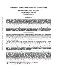
For the 2 × 2 channel, we carried out simulations for all four non-binary codes of Table I and also applied the Alamouti scheme with codes A and D. In order to compare schemes of the same overall rate, for the Alamouti scheme we applied QAM with 𝑞 constellation points, which can be considered the “natural” constellation size for a 𝑞-ary channel code.
10
0
ACKNOWLEDGMENT
Code A, D4(64) mapping Code A, Alamouti, 64−QAM code B, D (64) mapping
10
This work is supported by INFSCO-ICT-216203 DAVINCI (ict-davinci-codes.eu) funded by the European Commission and the Spanish Government under grant TEC2008-06327C03-03/TEC. We would like to thank Miquel Payaró for helpful discussions.
4
−1
Code C, D (64) mapping 4
code D, D (256) mapping
WER
4
10
−2
10
−3
10
−4
Code D, Alamouti, 256−QAM Alamouti Shannon limit, R = 3 Alamouti Shannon limit, R = 4
R = 4.5
R=3
R EFERENCES
R=4
5
6
7
8
9 SNR [dB]
10
11
12
13
Figure 6. Word error rates with the proposed scheme and the Alamouti scheme for 2 × 2 MIMO channel
Fig. 6 shows the word error rates obtained by simulation. The dotted curves have been obtained by mapping the SNR of the MIMO channel to its CM capacity, from which the mutual information per coded bit is obtained by simply dividing through log2 𝑞, the number of bits per symbol and applying the results of Fig. 2. We can observe that the results obtained by this indirect approximation provide a reasonable match to the results obtained directly with the MIMO channel. There is a noteable difference between the performance of the direct mapping and the corresponding Alamouti scheme which applies the same channel code: for code A, the difference is about 2 dB while for code D, the gap exceeds 3.5 dB. Fig. 6 also shows the Shannon limit of the Alamouti scheme for rates 𝑅 = 3 and 𝑅 = 4. These limits are outperformed by the direct mapping with code A and D, which means that these schemes are superior to the Alamouti scheme with any channel code. The Shannon limits for BICM with {8, 16}QAM are close to those of the Alamouti scheme for 𝑅 ∈ {3, 4} and are also exceeded by codes A and D (see also [7]), which means that these schemes perform better than any binary coding scheme. VII. C ONCLUSIONS We have shown how non-binary coding can be applied to a vector channel using as a particular case non-binary LDPC codes for MIMO transmission. The design principle is to provide a good channel for the coding scheme, which results in a simple direct mapping from the code symbols to the transmit vectors. At the receiver side, this leads to a very simple optimum soft demapper and hence the system complexity is concentrated in the channel decoder. Simulations for the 2 × 2 channel show that the performance is better than any binary (BICM) scheme and better than the Alamouti scheme with any channel code. A possible drawback of the proposed direct mapping is that the spectral efficiency is limited by the field size of the channel code.
[1] M. C. Davey and D. MacKay, “Low-density parity check codes over GF(𝑞),” IEEE Commun. Lett., vol. 2, no. 6, pp. 165–167, June 1998. [2] C. Poulliat, M. Fossorier, and D. Declercq, “Design of regular (2,𝑑𝑐 )LDPC codes over GF(𝑞) using their binary images,” IEEE Trans. Commun., vol. 56, no. 10, pp. 1626–1635, Oct. 2008. [3] F. Guo and L. Hanzo, “Low complexity non-binary LDPC and modulation schemes communicating over MIMO channels,” in IEEE Vehicular Technology Conference (VTC), Los Angeles (USA), Sept. 2004. [4] O. Alamri, S. X. Ng, F. Guo, S. Zummo, and L. Hanzo, “Spherepacking modulated space-time coding using non-binary LDPC codes iterative-detection,” in IEEE Wireless Communications and Networking Conference (WCNC), Las Vegas, (USA), March 2008. [5] G. Li, I. J. Fair, and W. A. Krzymie´n, “Low-density parity-check codes for space-time wireless transmission,” IEEE Trans. Wireless Commun., vol. 5, no. 2, pp. 312–322, Feb. 2006. [6] R. Peng and R.-R. Chen, “Application of nonbinary LDPC cycle codes to MIMO channels,” IEEE Trans. Wireless Commun., vol. 7, no. 6, pp. 2020–2026, June 2008. [7] S. Pfletschinger and D. Declercq, “Getting closer to MIMO capacity with non-binary codes and spatial multiplexing,” in IEEE Globecom, Miami, USA, Dec. 2010. [8] Y. Li and W. E. Ryan, “Mutual-information-based adaptive bit-loading algorithms for LDPC-coded OFDM,” IEEE Trans. Wireless Commun., vol. 6, no. 5, pp. 1670–1680, 2007. [9] P. Fertl, J. Jaldén, and G. Matz, “Capacity-based performance comparison of MIMO-BICM demodulators,” in IEEE SPAWC, Recife (Brazil), July 2008. [10] M. Franceschini, G. Ferrari, and R. Raheli, “Does the performance of ldpc codes depend on the channel?” IEEE Trans. Commun., vol. 54, no. 12, pp. 2129–2132, Dec. 2006. [11] K. Brüninghaus, D. Astély, T. Sälzer, S. Visuri, A. Alexiou, S. Karger, and G.-A. Seraji, “Link performance models for system level simulations of broadband radio access systems,” in IEEE PIMRC, Berlin, Germany, Sept. 2005. [12] J. L. Massey, “Do communication engineers need information theory?” March 2004, presentation at FTW, Viena. [13] D. MacKay and M. Davey, “Evaluation of Gallager codes for short block length and high rate applications,” in IMA Workshop on Codes, Systems and Graphical Models, Aug. 1999. [14] D. Declercq and M. Fossorier, “Decoding algorithms for nonbinary LDPC codes over GF(𝑞),” IEEE Trans. Commun., vol. 55, no. 4, pp. 633–643, April 2007. [15] A. Bennatan and D. Burshtein, “Design and analysis of nonbinary LDPC codes for arbitrary discrete-memoryless channels,” IEEE Trans. Inform. Theory, vol. 52, no. 2, pp. 549–583, Feb. 2006. [16] E. Biglieri, G. Taricco, and E. Viterbo, “Bit-interleaved time-space codes for fading channels,” in Conference on Information Science and Systems (CISS), Princeton (USA), March 2000. [17] J. Kliewer, S. X. Ng, and L. Hanzo, “Efficient computation of EXIT functions for nonbinary iterative decoding,” IEEE Trans. Commun., vol. 54, no. 12, pp. 2133–2136, Dec. 2006. [18] M. Payaró and D. P. Palomar, “Hessian and concavity of mutual information, differential entropy, and entropy power in linear vector gaussian channels,” IEEE Trans. Inform. Theory, vol. 55, no. 8, pp. 3613– 3628, Aug. 2009. [19] T. Koike-Akino and V. Tarokh, “Sphere packing optimization and EXIT chart analysis for multi-dimensional QAM signaling,” in IEEE ICC, Dresden, Germany, June 2009. [20] N. J. A. Sloane, “Tables of sphere packings and spherical codes,” IEEE Trans. Inform. Theory, vol. 27, no. 3, pp. 327–338, May 1981. [21] C. B. Papadias and G. J. Foschini, “On the capacity of certain spacetime coding schemes,” EURASIP Journal on Applied Signal Processing, vol. 5, pp. 447–458, 2002.