MATEC Web of Conferences 244, 03007 (2018) https://doi.org/10.1051/matecconf/201824403007 ITEP’18
Non-destructive testing of automotive heat exchangers Katarzyna Peta1,*, Jan Żurek1, Adam Patalas1 1Poznan
University of Technology, Faculty of Mechanical Engineering and Management, 60-965 Poznan, Poland Abstract. The paper presents the results of non-destructive testing to the final control of automotive heat exchangers, which must meet a number of technological and exploitative requirements resulting from their working conditions. For the observation of images of heat exchangers, verification of geometrical dimensions and identification of surface and volume defects, the used methods were: computed tomography (highresolution microtomograph Phoenix v|tome|x), three-dimensional optical scanning (3D GOM ATOS III optical scanner), coordinate measuring technique (coordinate measuring machine Hexagon Global Performance 122210). The effectiveness of nondestructive testing in industrial conditions was assessed and the directions of further research in this area were indicated. Keywords: heat exchangers, non-destructive testing, computed tomography, 3D optical scanning, quality control
1 Introduction Non-destructive testing allows the assessment of technical objects without causing changes in their microstructure and exploitative properties, also allow to determine their geometrical dimensions, detect material defects and appoint the properties of the used materials. Their aim is to improve the effectiveness of detecting irregularities in products and to minimize production time and the costs of control tests [1-3]. Non-destructive testing methods are of particular importance in the control of automotive industry products and contribute to ensuring the reliability and safety of motor vehicles. The size of production in the automotive industry induces to look for new solutions in the field of widely understood product control, including automotive heat exchangers, which final assessment is of key importance in the proper functioning of the vehicle. Detection of their irregularities prevents the leakage of cooling liquid and the failure of the engine cooling system or car air conditioning. Therefore, the identification of possible defects at the production stage affects their reliable usage [4]. The main technology used during the manufacturing of automotive heat exchangers is brazing in a furnace in controlled nitrogen atmosphere. Consequently, special attention during the control is paid to their assembly quality, which essentially decide about final *
Corresponding author:
[email protected] Reviewers: Oleksandr Kravchenko, Vladimír Stuchlý
© The Authors, published by EDP Sciences. This is an open access article distributed under the terms of the Creative Commons Attribution License 4.0 (http://creativecommons.org/licenses/by/4.0/).
MATEC Web of Conferences 244, 03007 (2018) https://doi.org/10.1051/matecconf/201824403007 ITEP’18
durability. The development of brazing technology poses new challenges for a discipline of non-destructive testing of automotive heat exchangers. Research methods which are adequate to industrial conditions has been distinguished [5-7]: - computed tomography, - three-dimensional optical scanning, - coordinate measuring technique. In the paper [8] a comparison of the results of research cube measurements made for the analysis using the methods of coordinate measuring technique, optical scanning and computed tomography were presented. Each of these methods enables effective measurement of the research cube and it was considered deliberate to carry out further research in order to search for areas of non-destructive testing methods. The authors [9] pointed out to the legitimacy of using optical measurement systems to control products in automated production and the rightness of development of this field of metrology. In the paper [10] a thermovision and computed tomography for the evaluation of products were discussed. Insufficient number of studies on effective and successful methods of their control, in particular those produced in special processes has been indicated. The authors [11] presented a comparison of the results of geometry measurements of the object obtained by destructive micrographic method and non-destructive three-dimensional optical scanning method. The first one provides more information about the material properties of the product but from the point of view of industrial conditions the latter is characterized by greater utility. The works [5-11] indicate the purposefulness of using non-destructive testing, which application in industrial practice is insufficiently discussed.
2 Research methodology Non-destructive tests were carried out on car radiators, which core was made of cladded tapes: aluminium-manganese alloy AA3003 (core material) and aluminum-silicon alloy AA4343 (clad material). Additional parts of the radiator are tanks and gaskets clinched on its core made from polyamide PA6 and terpolymer EPDM. Radiators were made in a controlled atmosphere of nitrogen in a radiation-convection furnace according to the CAB technology (Controlled Atmosphere Brazing) and these steps followed sequentially: thermal degreasing, fluxing, heating, brazing, cooling in nitrogen atmosphere, cooling in the air. The basic mechanical properties and chemical composition of materials used in radiators production is given in table 1. Table 1. Basic mechanical properties and chemical composition of aluminium alloys AA3003/AA4343 Alloy
Fe
Si
Cu
Mg
Mn
Zn
Al
AA3003 (core)
0.7
0.6
0.05-0.2
0.05
1.01.5
0.1
Re.
0.1
0.2
AA4343 0.8 4% (clad)
6.8-8.2
0.25
0.05
Tensile Yield Elongation strength point % 2 N/mm2 N/mm
115.00
58.00
37.00
Re.
The major methods of non-destructive testing including computed tomography, threedimensional optical scanning, coordinate measuring technique used for verification of geometrical dimensions and identification of possible defects in the automotive car radiators are compared in table 2. For each method, the five measurements of the analysed object were made. 2
MATEC Web of Conferences 244, 03007 (2018) https://doi.org/10.1051/matecconf/201824403007 ITEP’18 Table 2. The methods of non-destructive testing of car radiators Method
Measuring device
Software
Measurement accuracy
Coordinate measuring technique
Hexagon Global Performance 122210
PC-DMIS
from 3.4 μm to 3.7 μm
Three-dimensional optical scanning
3D GOM ATOS III
Atos Professional V8
from 12.4 μm to 14.9 μm
Computed tomography
Phoenix v|tome|x
VGStudio MAX 2.2
from 10.2 μm to 11.45 μm
The non-destructive assessment of car radiators included the verification of its geometrical dimensions using a Hexagon Global Performance 122210 coordinate measuring machine with a measurement range of 1200 x 2200x 1000 mm and accuracy of measurements 3.4-3.7μm. The coordinate measuring machine receives the set of points of the measured object in coordinates X, Y, Z, which location enables the contact measuring head, and their position - measuring straightedges in each axis. PC-DMIS computer software allows to obtain the characteristic dimensions of the measured object. The results obtained coordinate measuring technique was compared with the results received three-dimensional optical scanning. The optical scanner 3D GOM ATOS III, as opposed to measurements of single points in coordinate method, captures the geometry of whole objects as clouds of points or a triangle grid. The 3D optical scanner operates on the basis of Triple Scan technology, in which the measurement takes place using two cameras. On the surface of the measured object, patterns consisting of stripes are displayed, and the whole is recorded by two cameras on a stereoscopic basis. The points of the threedimensional surface are designated from intersections of the beams left and right visual cameras. This solution enables to measure light reflective surfaces and objects with complicated shapes, including indentations. The measurements were made in Blue Light Technology, in which the optical scanner uses blue narrowband light to filter out disturbing light coming from the surroundings. Depending on the measuring field, the measurement accuracy is from 12.4 μm to 14.9 μm. The Atos Professional V8 software was used for dimensional analysis of the car radiators. The verification of the car radiator dimensions were complemented by computed tomography method using a high-resolution microtomograph Phoenix v|tome|x. The tomographic image occurs as a result of measurements of the radiation absorption penetrating of the examined object, the solid of which is divided into cells called voxels with identical linear coefficients of radiation absorption. The cross-sectional image after reconstruction is a quantitative map of linear radiation absorption in the voxels located in the scanned layer. On the basis of the obtained point cloud, the dimensional characteristic of the analyzed object, including its internal structure, are obtained. The Phoenix v|tome|x microtomograph is equipped with a 300kV single-pole microfocus light with the power of 500W of an open type and a liquid cooling system. The minimum voxel size is 2 μm, while the detection of details is less than 1μm. The device has a GE DXR digital detector with a resolution of 2000 x 2000 pixels, where the size of a single pixel is 200 μm. The VGStudio MAX 2.2 software was used for dimensions evaluation of the car radiators.
3 Research results In order to verify the legitimacy and the possibility of using non-destructive tests in the production process of automotive heat exchangers, the geometrical dimensions of car radiators specified in control documentation and checked in the current production of these products were measured. The obtained measurements results of car radiator diameters are 3
MATEC Web of Conferences 244, 03007 (2018) https://doi.org/10.1051/matecconf/201824403007 ITEP’18
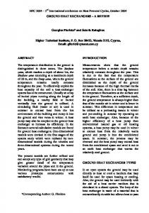
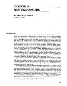
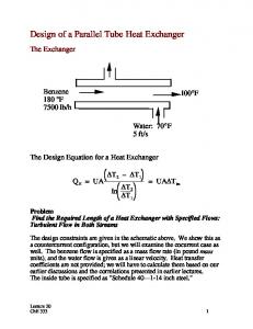
presented in figures (Fig. 1 - the results obtained using the coordinate measuring technique, Fig. 2 - three-dimensional optical scanning, Fig. 3 - computed tomography).
Fig. 1. The results of measurements of car radiator diameters obtained by coordinate measuring technique
Fig. 2. The results of measurements of car radiator diameters obtained by three-dimensional optical scanning
4
MATEC Web of Conferences 244, 03007 (2018) https://doi.org/10.1051/matecconf/201824403007 ITEP’18
Fig. 3. The results of measurements of automotive car radiator diameters obtained by computed tomography
The comparison of obtained measurements results automotive car radiators geometrical dimensions with nominal sizes together with an indication of the location on the analysed object are presented in Table 3. The average measurements results are compiled for three methods: coordinate measuring technique, three-dimensional optical scanning and computed tomography. The car radiators measurements were repeated 5 times, specifying the mean values and standard deviations. The measurements results of geometrical dimensions of automotive car radiators, depending on the measuring device which was used, they differ from nominal values from 0.010 mm to 0.029 mm. These results are within the fields of tolerance dimensions specified in the technical documentation (T = ± 2.000 mm for spacing of header plates and T = ± 2.500 mm for spacing of the plastic tank key fragments), providing the stability of the manufacturing process of these products. Taking into account the obtained measurement results and the accuracy of devices specified in their specifications (coordinate measuring technique - from 3.4 μm to 3.7 μm, three-dimensional optical scanning - from 12.4 μm to 14.9 μm, computed tomography - from 10.2 μm to 11.45 μm) it allows to use of the nondestructive testing in industrial practice.
5
MATEC Web of Conferences 244, 03007 (2018) https://doi.org/10.1051/matecconf/201824403007 ITEP’18 Table 3. The results of measurements of car radiator diameters obtained by non-destructive methods
Measured diameter
Nominal value mm
l1 =736.000 T = ±2.500
l2=620.300 T= ±2.000
l 3= 717.400 T= ±2.500
l 4= 745.300 T= ±2.500
6
Average Standard Measurement measurement deviation method result mm mm Coordinate measuring technique
l1 = 735.983
s1 = 0.017
Threedimensional optical scanning
l1 = 735.972
s1 = 0.028
Computed tomography
l1 = 735.980
s1 = 0.020
Coordinate measuring technique
l2 = 620.284
s2 = 0.016
Threedimensional optical scanning
l2 = 620.275
s2 = 0.025
Computed tomography
l2 = 620.279
s2 = 0.021
Coordinate measuring technique
l3 = 717.390
s3 = 0.010
Threedimensional optical scanning
l3 = 717.373
s3 = 0.027
Computed tomography
l3 = 717.382
s3 = 0.018
Coordinate measuring technique
l4 = 745.286
s4 = 0.014
Threedimensional optical scanning
l4 = 745.271
s4 = 0.029
Computed tomography
l4 = 745.281
s4 = 0.019
MATEC Web of Conferences 244, 03007 (2018) https://doi.org/10.1051/matecconf/201824403007 ITEP’18
4 Conclusions Non-destructive testing allows to effectively detect the irregularities in automotive heat exchangers, while their time-consumption is comparable to destructive micrographic control. Thus, they allow to evaluate products without changing their microstructure and exploitative properties. The results of measurements of geometric dimensions of automotive radiators were in the tolerance fields included in the design documentation, which confirms the stability of their production processes. All of the used methods are also applicable in the production process, especially for random control of geometrical dimensions and potential defects of analysed products. The most noteworthy device for detecting irregularities in products is the computer microtomograph that allows not only obtaining a measurement accuracy comparable to a three-dimensional optical scanner and a coordinate measuring machine, but also surface and volume evaluation of automotive heat exchangers with the possibility of imaging its interiors. Computed tomography is cost-consuming (purchase and exploitation of the device), but it allows to carry out a wide range of automotive heat exchanger tests. The literature study and the obtained research results justify the continuation of work related to the practical application of non-destructive testing. This will include the comparison of the destructive micrograph method with the non-destructive computed tomography tests, the three-dimensional optical scanning and coordinate measuring technique. Therefore, a comprehensive assessment of heat exchangers is planned, including the characteristics of geometric dimensions and identification of defects (according to the technical documentation), using only the non-destructive testing.
References 1. 2. 3. 4. 5. 6. 7.
8.
J.P. Kruth, M. Bartscher, S. Carmignato, R. Schmitt, L. De Chiffre, A. Weckenmann, Computed tomography for dimensional metrology. CIRP Ann-Manuf. Techn., 60, 821842 (2011) S.K. Dwivedi, M. Vishwakarma, A. Soni, Advances and Researches on Non Destructive Testing: A Review. Mater. Today-proc., 5, 3690-3698 (2018) R. Hanke, T. Fuchs, N. Uhlmann, X-ray based methods for non-destructive testing and material characterization. Nucl. Instrum. Meth. A, 591, 14-18 (2008) A. Dubey, Investigation on Suitability of Aluminium to Copper in a Radiator. Adv. Mater. Res-switz., 3, 16-23 (2015) S. Kumar, D. Mahto, Recent trends in industrial and other engineering applications of non-destructive testing: a review. International Journal of Scientific & Engineering Research, 4, 183-195 (2013) J. Kastner, B. Harrer, H.P. Degischer, High resolution cone beam x-ray computed tomography of 3D microstructures of cast Al-alloys. Mater. Charact., 62, 99-107 (2011) P. Chaudhuri, P. Santra, S. Yoele, A. Prakash, D. Reddy, L. Lachhvani, G. Jagannathan, Y. Saxena, Non-destructive evaluation of brazed joints between cooling tube and heat sink by IR thermography and its verification using FE analysis. Nondestructive Testing and Evaluation International, 39, 88-95 (2006) B. Gapiński, M. Wieczorowski, L. Marciniak-Podsadna, B. Dybala, G. Ziolkowski, Comparison of Different Method of Measurement Geometry using CMM, Optical Scanner and Computed Tomography 3D. Procedia Engineer., 69, 255 – 262 (2014)
7
MATEC Web of Conferences 244, 03007 (2018) https://doi.org/10.1051/matecconf/201824403007 ITEP’18
9.
J. Jaworski, R. Kluz, T. Trzepieciński, Research on Accuracy of Automatic System for Casting Measuring. Archives of Foundry Engineering, 16, 49-54 (2016) 10. K. Żaba, S. Nowak, M. Kwiatkowski, M. Nowosielski, P. Kita, A. Sioma, Application of non-destructive methods to quality assessment of pattern assembly and ceramic mould in the investment casting elements of aircraft engines. Arch. Metall. Mater., 59, 15171524 (2014) 11. H. Lend, K. Ratas, P. Peetsalu, Measurement of Geometry of Small Axisymmetric Sheet Metal Component after Forming. Mater. Sci-Medzg+, 21, 473-478 (2015)
8