Aug 22, 1995 - Example of Vorono Maximum Likelihood Estimator . ... estimator (MLE) for the mixture of two uniform random variables, as a special case of the.
Non Parametric Maximum Likelihood Estimation of Features in Spatial Point Processes using Vorono�� Tesselation Denis Allard Department of Statistics, University of Washington Seattle, Washington, 98195-4322, USA August, 22, 1995
Abstract
We address the problem of estimating the support domain of a bounded spatial point process in the presence of background noise. This happens for example when detecting a mine�eld from aerial observations. The image returned by the electronic device contains putative mine locations and is corrupted by clutter. The problem is to �nd the boundaries of the mine�eld and to estimate the number of mines inside the mine�eld. The maximum likelihood solution is worked out in the case of a mixture of uniform random variables by use of a natural tesselation of the plane de�ned by the data themselves: the Vorono�� tesselation. The method is then tested for 1 and 2 dimensional simulated processes it is shown that this estimator is robust when applied to more regular point processes.
During this work the author has been supported in part by the O�ce of Naval Research under Contract N 00014-91-J-1074. The author is grateful to Adrian Raftery, Julian Besag, Christian Lantu�ejoul and Chris Fraley for helpful comments, suggestions and careful reading. The Vorono tesselation procedure has been provided by Christian Lantu�ejoul from the Centre de G�eostatistique, Fontainebleau, France
1
Contents
1 Introduction 2 The Maximum Likelihood Estimator
3 4
3 Results of Simulations in 1d 4 Simulations in 2d - The mine�eld detection problem
8 9
2.1 De�nition of the problem . . . . . . . . . . . . . . . . . . . . . . . . . . . . . . . 2.2 The Vorono�� tessellation . . . . . . . . . . . . . . . . . . . . . . . . . . . . . . . . 2.3 The template MLE . . . . . . . . . . . . . . . . . . . . . . . . . . . . . . . . . . .
4 6 7
4.1 Presentation of the problem . . . . . . . . . . . . . . . . . . . . . . . . . . . . . . 9 4.2 Approximate MLE algorithms . . . . . . . . . . . . . . . . . . . . . . . . . . . . . 10 4.3 Robustness of the estimator . . . . . . . . . . . . . . . . . . . . . . . . . . . . . . 17
5 Discussion 6 Example Appendix References
19 19 21 24
List of Figures 1 2 3 4 5 6
Example of Vorono�� Maximum Likelihood Estimator Examples of unrestricted MLE . . . . . . . . . . . . Low density estimation . . . . . . . . . . . . . . . . . Non uniform poin processes . . . . . . . . . . . . . . Earthquake example . . . . . . . . . . . . . . . . . . Function `0 and likelihood function `0 (x) . . . . . . .
. . . . . .
. . . . . .
. . . . . .
. . . . . .
. . . . . .
. . . . . .
. . . . . .
. . . . . .
. . . . . .
. . . . . .
. . . . . .
. . . . . .
. . . . . .
. . . . . .
. . . . . .
. . . . . .
4 10 14 18 20 22
. . . .
. . . .
. . . .
. . . .
. . . .
. . . .
. . . .
. . . .
. . . .
. . . .
. . . .
. . . .
. . . .
. . . .
. . . .
. 9 . 15 . 16 . 17
List of Tables 1 2 3 4
1 dimensional simulations . . . . . . . . . . . . . . Mine�eld simulations: in�uence of the SNR . . . . Mine�eld simulations: in�uence of the sample size Non uniform point processes . . . . . . . . . . . . . 2
. . . .
1 Introduction In this paper, we want to address the problem of estimating the support domain of a bounded spatial point process in the presence of background noise. This happens quite often in image analysis, and a typical example is the detection of a mine�eld from aerial observations. The image returned by the electronic device contains putative mine locations and is corrupted by clutter. The problem is to �nd the boundaries of the mine�eld and to estimate the number of mines inside the mine�eld. We will only brie�y address the problem of testing the presence of two populations since many standard methods are applicable, see for example Diggle (1983), Cressie (1993) and references therein. We will therefore assume that the data are known to contain two populations, and focus on the estimation of the domain of a bounded point process in the presence of a background noise. Much of the work on model-based clustering has been made in the context of mixtures of Gaussian densities, possibly with noise, see for example Ban�eld and Raftery (1993) and Celeux and Govaert (1993). Less attention has been paid to the estimation of mixture of point processes in the context of spatial statistics. Mixtures of uniform random Variables have been considered as early as 1954 by Cherno� and Rubin (1954). They solved completely the problem of the one dimensional maximum likelihood estimator (MLE) for the mixture of two uniform random variables, as a special case of the estimation of a discontinuity in a density. They showed that these estimates di�er from the parameter by an amount which is of the order of magnitude of 1=n where n is the sample size. Gupta et al. (1986) worked the estimation of an arbitrary mixture of uniform distributions on the line using moment estimators. In this paper we propose a maximum likelihood algorithm to �nd the support domain of a mixture of two uniform random variables in IR d , when one of the variables has a domain completely included in the other one, as for example in image analysis. The support domain is searched within a �nite set of template domains de�ned by the data themselves: the Vorono�� tesselation. We propose for estimator the union of the Vorono�� polygons maximizing the likelihood of the model. Some geometrical constraints can be added, depending on the phenomenon under study. For example, the domain can be restricted to be connected (in one piece), without holes and with a regular boundary. This method is very general and does not require any assumption on the shape of the domain. Figure 1 shows for example an arrow-headed mine�eld with its estimate. The outline of the paper is the following. In section 2, we give the MLE for the parameters of a mixture of uniform random variables in IR d . On the line, simulations show that our estimator has better performances than the true MLE worked out by Cherno� and Rubin, both in terms of bias and variance. This is done in section 3. Simulations in the plane are carried out in section 4, having in mind the mine�eld detection problem. It is then shown experimentally that the algorithm seems to be consistent. Simulations show also the robustness of this estimator 3
1.0 0.0
0.2
0.4
0.6
0.8
1.0 0.8 0.6 0.4 0.2 0.0 0.0
0.2
0.4
0.6
0.8
1.0
.. . . . . . . . . . .... . . . . . . . .. . . .... . .. . . . . . .. . . . ... . .. .. . .. . . . ... . . .. . .. . . . . .. .. . . . . . ... . .. . . . .. . . . . . .. .. . . . . . .. . . . . ... .. .... . . .. . .. ..... . .. .. .. . . . . .. . . . . .. . . . . . . . . . . . .. . . . . .. .. .. . . . . . .. . . . . .. .. . . . .. . .. . . . . . . . . . . . . .. .. . .. . . . . .. . . .. . . . ... . .. . . . . . . . . . .. . . . . .. . .. . . . . .. . . . .. . . . . . .. .. . . . . . .. . .. . . . . . .... . .. . . . . . . . . . . . . . . . . . . . . .. . . . .. . . . . . . . .. . . . . .. . . . . . . . . . . .. . .. . . . . .. . . . . . . . . ... .. . . . . . . . . . . .. . . . . . . . . . . .. . . . ... . . . . . . . . . .. .. . . . . . . . . . ... . . . .. . . . . . .. . . . . . . .. . . . . . . . . . ...... . . . . ... . . .. .. . . ... . . . . . . .. .... . . . . . .. . .. . .. . . .. . . . . . . . .. . .... . .. .. .. . . . . . . . . .. . .. . . ....... .. .. ..... ... ... . . .. . . . .. . . . . . . . . .. . . . . . . . . .. .. . ... ........ ... . .... .. . .. .. . . .. .. . . .. . .... . ... . ... ...... ... . . ... ... .. .. . . . . . . . .. . ... ..... . . . .. . . . . .. . ..... .. ..... ... . . .. . . . . . . . .. .. . . . . . . . ... . ...... . . . . . . .... . .. . . . . . . . . . . .... .... .. . .. .. .. . .. . . . . . . . . . . .. ... . .. . . . . .. . .. .... . .. ... . . .. . . .. . . . . . . .. .. . .. . .. . .. . . . . .. .. . . . . . . . . .... .. .. .. .. . . . . . . . . . . .. . .. . . . . . . . . . . .. . . ..... . . . .. .. .. . . . . .. .... . . . . . . . . . .. . . .. .. . . . ... . . . . .. . .. . . . . . . . . . . . . . . . . . . .. . . . . .. . ... . . . . . . . .. . . . . .. . . .. . . .. . . .. . . . . . . .. .. . . 0.0
0.2
0.4
0.6
0.8
1.0
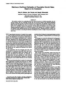
Figure 1: An example of the Vorono�� - Maximum Likelihood Estimator. Detection rate is 97%� False alarm rate is 4.5%. The lines indicate the true domain. Black squares indicate points detected as mines. Dots indicate points detected as clutter points. when the point process is more regular than the uniform model. In appendix we give the proof of consistency of the Vorono�� based operator on the line and we show that its e�ciency is of the order of 1=n2 . In higher dimensions, a rigorous proof seems intractable.
2 The Maximum Likelihood Estimator 2.1 De�nition of the problem
Consider a compact set K of IR d on which we observe a random sample fXi g from a mixture of two uniform random variables: UK with support K and UA0 with a support A0 included in K . We will assume that A0 is simply connected, that is, it is in one piece and without holes. A random point X is either a point of UA0 with probability p or a point of UK with probability 1 ; p. Both A0 and the mixture parameter p are unknown and are to be estimated simultaneously. The density associated of a point x 2 K is f (x) = p 1 (x) + 1 ; p � x 2 K
a0
A0
k
where a0 and k denote respectively the Lebesgue measure of A0 and K (length, area, volume for d = 1� 2� 3 respectively). Without loss of generality, we assume that k = 1. Hence, the �nal 4
form of f (x) is
(1) f (x) = ap 1A0 (x) + 1 ; p� x 2 K 0 Note that this mixture is always identi�able if p > 0, which we will assume henceforth. If p = 1,
there is no background noise, and the problem is the estimation of the boundary of a point process. This problem has been widely addressed, see for example Ripley and Rasson (1977). For a sample size n, the likelihood is then � �n n Y L(X� � A� p) = f (Xi ) = ap 1A (Xi ) + 1 ; p = ( ap + 1 ; p)M (1 ; p)n;M (2) i=1
where
M=
m X i=1
1A(Xi )
is the number of points in A. The likelihood is not directly workable since the mixture parameter p is not known, and has to be estimated with A0 . We will therefore replace the likelihood approach by a partial likelihood approach as de�ned in Cox (1975). In the situation that A0 is known, the MLE for p is well known and given by M ; an p^ = (1 ; a)n Since it is a linear function of M , the counting variable in A, it is well known that p^ is the UMVU estimator for p. In particular, it is unbiased and has variance V ar(^p) = p0 (1 ; p0 )(1 ; a20 );2 n;1 , with p0 being the probability of a point to belong to A0 : p0 = P (X 2 A0 ) = p + a0 (1 ; p). When A0 is not known, the �nal estimate for p will have to use the estimate for A0 . The latter is found by considering the partial likelihood, obtained when p is replaced by p^. After rearranging the terms, this yields to a very simple expression for the likelihood � �n � M �M � n ; M �n;M Lp(X� � A) = n1 a 1;a or more conveniently for the log-likelihood � A) = ;n ln n + M ln M + (n ; M ) ln n ; M `p(X� a 1;a
(3) (4)
In one dimension, if K and A0 are intervals of IR with A0 � K , it is well known that the MLE A^ is an interval whose endpoints are one of the n + 2 following points: 0, 1 or one of the data points Xk . Cherno� and Rubin (1954) showed that this estimator is consistent and that its variance is of order of 1=n2 . In two dimensions, if A0 is a rectangle included in K , the 5
MLE A^ is a rectangle de�ned by two, three or four data points: two if they are at two opposite corners of the rectangle, three if 1 data point is at a corner and two data points are on the opposite sides and four if the data points are on the four sides of the rectangle. The reason is that given m data points, the rectangle maximizing the likelihood and containing these m points is the smallest possible, de�ned by the two opposite corners whose coordinates are equal to the smallest abscissa and ordinate and the largest abscissa and ordinate respectively. There are C4n+4 of those rectangles to test. The MLE A^ will be the one maximizing `0p. In general, if A0 is a parallepiped in dimension d, there are C2nd+2d likelihood to compute. By generalizing Cherno� and Rubin's argument, it can be shown that the MLE is consistent and that the estimators of the bounds of the intervals de�ning A0 have a variance in 1=n2 . Our goal however is to �nd an estimator for A0 in the most general case, that is i) for an arbitrary dimension of the space, ii) for an arbitrary and unknown shaped A0 . In this case, the partial likelihood (3) does not provide a way to �nd a MLE without additional constraints on A, as is always the case when using a MLE approach for a density estimation. This can be seen by putting a spike of arbitrary large magnitude and correspondingly narrow width at each observation xi , thus creating a likelihood that is arbitrary large. One approach is then to consider a restricted class of candidate estimators on which a maximum is well de�ned, and �nd the candidate within that class maximizing the likelihood. We propose to consider for A a �nite class of template sets given by the data themselves: the Vorono�� cells.
2.2 The Vorono�� tessellation
A collection C of points fxi g in a compact set K of IR d induces a natural subdivision of K into disjoint \territories": we assign to xi the part of K closer to xi than to any other xj . This subdivision of K , denoted V (C ), is referred to as the Vorono�� tessellation (or sometimes as the Dirichlet tessellation). Clearly, in this construction each cell contains one and exactly one point xi called the \nucleus" of the cell. Equivalently, each cell is the intersection of the n ; 1 half-spaces closer to xi than to xj . As a consequence, the cells are convex polytopes: line segments for d = 1, convex polygons for d = 2, convex polyhedra for d = 3, and son on. This property gives also an easy algorithm to compute the Vorono�� tessellation, although it is not the most e�cient with a computational cost proportional to n2 . Preparata and Shamos (1985) give an algorithm that is O(n ln n). The Vorono�� tessellation has been used to model natural phenomena in many diverse �elds, for example in agriculture, astrophysics, metallurgy, biology and physics where they provide an appealing description of the concept of \area of in�uence" and because it contains all the proximity information de�ned by a set of points. However, to the best of our knowledge, Vorono�� polygons have not been used yet in estimation problems in statistics. When the particles of C are in mutual general quadratic position, that is when i) no more 6
than d points lie on d ; 1-plane of IR d , ii) no more than d + 1 points lie on the boundary of a dball, it can be shown (see e.g. M ller (1994)) that under these conditions a vertex of the Vorono�� tessellation is the vertex of exactly d + 1 cells, and that the intersection between two Vorono�� cells is either empty (if they are not adjacent) or a d ; 1 convex polytope (as an intersection of two convex polytopes). Hence, for d = 3, the intersection of two cells is either empty or a convex polygon� for d = 2, each vertex of V (C ) is the vertex of exactly three polygons, and if two cells are adjacent, they share an edge. If C is a random point process absolutely continuous with respect to the Poisson point process, any realization will almost surely satisfy conditions i) and ii). This will not always be the case in the examples seen later. For instance, if C is the 2-d square grid, the Vorono�� tessellation of C is the set of contiguous squares with half- integer coordinates. In this case, each vertex is the vertex of exactly four of these squares. Clearly, a regular grid violates condition i). In two dimensions, quantities of interest for V (C ) include the distribution of the number of vertices, the distribution of the perimeter, the area, the angles and the lengths of the sides of the polygons. Unfortunately, almost nothing is known for general point processes, and only a few theoretical results are known for the homogeneous Poisson point process. In this last case, let V be a typical Vorono�� cell and let jV j and j@V j be its volume and perimeter. Then,
E (N (V )) = 6� E (j@V j) = 4�;1=2 � E (jV j) = �;1 where � is the Poisson intensity and N (V ) is the number of vertices of V . The Poisson intensity plays only the role of a scale factor. The number of vertices (or equivalently, number of edges and number of neighbors) is insensitive to �, whereas the area of the cells depends on �;1 . In particular, the higher the density of points, the smaller the cells. It is therefore clear that the contrast between the densities within and outside A0 will be determinant for the performances of the estimator. Hinde and Miles (1980) performed Monte-Carlo simulations to estimate higher moments and the distribution of some quantities of interest. A theoretical review of random Vorono�� tessellation can be found in M ller (1994).
2.3 The template MLE
The template maximum likelihood estimator of A, denoted A^, is thus de�ned as the union of Vorono�� polygons maximizing the likelihood (3) and (4). The power set of the Vorono�� cells contains 2n possible choices for A, and it is clear that it is not possible to scan them all to �nd the template MLE. If no restrictions are made on the shape of A, there is actually no need to do so because the following result holds:
Proposition 1 For a mixture of two uniform random variables on A0 and K with A0 � K , the Vorono�� based MLE is the union of the m ^ smallest Vorono�� cells, for some m^ .
7
Proof: First �x the number of cells, say m. Then, the log-likelihood is a function of the area
of the domain, a. Let consider the function f (a) given by the log-likelihood (4), when m is considered as a constant
whose �rst derivative is
f (a) = ;n ln n + m ln ma + (n ; m) ln n1 ;; m a�
;m f 0 (a) = aan (1 ; a)
The second derivative is always positive indicating that f (a) reaches a minimum for a = m=n is decreasing on (0� m=n) and increasing (m=n� 1). Since the density of points is higher in A0 than in K , a0 is always less than M (A0 )=n (where M (Ao ) is the number of points in A0 ). Hence, we are only interested in the solutions for a � n=m. Therefore, because f (a) is decreasing for these values of a, the choice of A maximizing the likelihood is the one minimizing the area a. Since we restrict ourselves to union of Vorono�� cells, the solution is eventually the m smallest cells. As a consequence, the MLE for A will be the union of the m^ smallest cells, where m^ is such that it maximizes the log-likelihood (4). 2 In summary, the MLE �nds the solution separating the cells in two groups, the group of the smaller cells and the group of the larger cells, by maximizing the contrast between the two groups, in the sense of maximizing the log-likelihood (4). But by doing so, the MLE will not necessarily be connected since it could �nd a (relatively) small Vorono�� cell outside A0 . How to overcome this problem and to end up with a connected solution depends on the dimension of the problem. For a 1-dimensional problem, since the line is a fully ordered set, it is possible to prove the consistency of the estimator and we can compare its performance with Cherno� and Rubin's estimator. In higher dimension, we have to �nd approximative ad-hoc solutions, and no formal proofs are available.
3 Results of Simulations in 1d Since we assumed that A0 is connected, the MLE is restricted to the subset of solutions having this property. A^ will be a segment whose endpoints are the midpoints between the data (except at the two extremities). It is shown in appendix that this estimator is also consistent and has also a variance of the order of 1=n2 . In order to compare the relative performances of the two approaches, simulations have been performed for a mixture of a uniform random variable on A0 = !0:25� 0:50] (probability p = 1=3) and a uniform random variable on !0� 1]. 500 simulations have been carried out for various values of the number of data points n. In this simulation exercise, the two estimators have been computed on the same set of simulations, allowing direct comparison. 8
n = 60
n = 120
n = 180
n = 240
n = 300
MLE Vor. MLE Vor. MLE Vor. MLE Vor. MLE Vor.
E !^a] �(^a) E !^b] �(^b) E !^p] �(^p)
0.315 0.274 0.260 0.255 0.252 0.253 0.253 0.253 0.252 0.252 0.149 0.095 0.064 0.049 0.028 0.023 0.021 0.014 0.015 0.014 0.481 0.492 0.490 0.494 0.497 0.498 0.498 0.498 0.498 0.498 0.127 0.097 0.062 0.043 0.026 0.022 0.019 0.018 0.013 0.013 0.277 0.328 0.330 0.333 0.336 0.334 0.335 0.334 0.334 0.332 0.186 0.133 0.094 0.071 0.054 0.049 0.044 0.039 0.038 0.038 Table 1: Some statistics for 500 simulations of a mixture of uniform random variables on the line (p = 1=3. A0 = !0:25� 0:50]). The convergence of the estimators is experimentally quite clear on Table 1. They both tend to be unbiased and have a standard deviation behaving roughly as 1=n. Surprisingly, the Vorono�� approach leads always to better results than the absolute maximum likelihood approach, both in terms of variance and bias. It seems that the Vorono�� estimator is more stable than the true MLE estimator using the data points. These results are really encouraging because they give good support to the use of the Vorono�� cells as a template sets in higher dimensions.
4 Simulations in 2d - The mine�eld detection problem
4.1 Presentation of the problem
The method described in section 2.3 is valid for any dimension of the space. In this section, it will be illustrated in the plane, having in mind the mine�eld detection problem. It arises when an area has been surveyed using some imaging system, and it is thought that there may be one or several mine�elds contained within the surveyed area. The aim of the analysis is to determine whether there are mine�elds present, and what their boundaries are. Often, the area surveyed includes shallow water, beach area and a surface zone with vegetation. This area may include several di�erent mine�elds (or none). Processed images that return a list of putative mine locations are corrupted by clutter, due to objects that may look like mines at the image's level of resolution. It is anticipated that in the mine�eld there may be as many as one false alarm for every mine. We illustrate the Vorono�� based estimator for the mixture of uniform random variables 9
0.0
0.4
. .
. .. . ..
.
. . . . .
. ..
.
.
.
. . .. .
. .
. . .
..
. . . ..
.
.
0.6
.
. . .
.
. .
...
..
.
. . .
0.8
.. . .
. .
. .
.
.
. . . . ... .. ... . ..
.
.. .. .
.
. ..
. . ..
. 1.0
. 0.0
.. . . . . . .. .. . . . .. . . . . . . . . .. . . . . . . . . . . .. . . . . .. .. . .. . . . .. . .. . . . . .. . . . . . . .. . . .. . .. . . .. .... . . . . .. .. . . . . . . . .. .. . . . . . . . . . . . . .. .. . .. . .. . . . . . .. . .. .. . . . .. . . . . .. . . . . . . . . .. . . .. . . . ... . . . . . ... . . .. .. . . . . . . . . . . . . . . . . .. . . . . .. . . . . . . . . .. . .. . .. .. . .. . . .. . . . . . . . . . . . . .. ..... . . .. . . . . ... . . .. . . . . .. . . .. .. . . . . . .. . . . . .. . . . . . . . . ... . . . . . ..... .. . . ... . . . .. .. . . . . . . . . . . . . . . . . .. . ... . ...... . . . . . . .. .. . .. .. . ... .... .. . . . .. . . .. . . . . . . . . . . . . . . . . . .. . .. .. . . . . .... . . .. . .. . . . . . .. .. . . . . . . . . . . . . . . . . . . ... .. . . . . . .. . . ... . . .. .. . . . . . . .. . .. . . . . . .. . . . .. . . . .. .
.
.
.
.
.. .
.
. . .. .
.
.
.
.
..
1.0
. . .. . .
. .
.
. . . . . . .
. .
.
. . . .
. .
.
0.8
. .
.
.
.
.
.
.
0.2
.
.
0.6
. .. . . . . .. . . ... . . . .. . . . . . . . . . ... . . . . . . .. . . .. . . . . . . . . . .. ... .. .. .... .. .. .. . . .. . . .. . . . .. . . . . . .. . . . .. . .. . . .. . . . . . . . . . . .. ... . . . . .. . .. .. . . .. . . . . . . .. . . . . . . . .. . ... . . .... . . .. . . .. . . . . . ... . . .. .. . .. . . . . . . . . . . .. .. . .. .. . . . .. . . . . . . ... . . . . . .. .. . . . . .. .
..
. .
0.4
. .
0.2
0.8 0.6 0.4 0.2 0.0
.
0.0
1.0
. .
.
. . . . .. . . . . . .
.
.
0.2
0.4
0.6
0.8
.
.
.. . . . .
. .
. . .. . . . .
.
. . . . . .
.
.
.. . ... . .
. . .
. . ..
.. . . .. .
. 1.0
Figure 2: Examples of unrestricted MLE. The true area is indicated by the rectangle� black squares indicate points detected as mines. in this context. Clutter points on the image and mines within the mine�eld are assumed to be uniformly distributed. Some sort of inhibition process presenting a more regular pattern than pure randomness would perhaps be more appropriate. Choices of models are for example deterministic regular grids, hard-core processes or random Markov point processes. We will show experimentally later (in section 4.3) that the algorithm proposed for the uniform case is robust in the sense that it has very good performance on more regular point processes.
4.2 Approximate MLE algorithms
The complete solution of the mine�eld problem requires of course to test the existence of a mine�eld, and in the positive case to select the optimal number of pieces for A0 . These problems are not addressed in the present paper, but we will give some indication of how to solve it in our discussion. We assume for the moment that A0 is connected, and without holes. Under these assumptions the MLE of section 2 is no longer acceptable, as it can be seen on �gure 2. This �gure shows the unconstrained MLE solution for a rectangular domain A0 in the unit square with di�erent values of n and the signal/noise ratio, de�ned as r = p=a0 (1 ; p) (in the mine�eld terminology, the number of mines per clutter point in the mine�eld). The MLE is largely con�ned to A0 but includes also small polygons far away from the area of interest, since small polygons are likely to occur even outside A0 . A second typical pattern is quite visible on the right side image: the algorithm seeks the 10
best partitioning between small and large cells, regardless of the regularity of the solution. If A0 is know to be regular, as it is the case in the mine�eld problem, regular solutions should be preferred. Two strategies at least are possible: one can consider a penalized likelihood, in which a term penalizing irregular solutions is included through some quantitative measurements on these solutions. Possible choices are: penalizing a high perimeter/area ratio, penalizing cells with a high number of neighbors outside A over number of neighbors within A ratio. Another strategy is to restrict the MLE to be a union of Vorono�� polygons sharing the same properties as those assumed for A0 . This is equivalent to say that A^ belongs to the subset of the power set of V (C ) for which all the geometrical constraints are veri�ed. For example, in the mine�eld detection problem in addition to the connectivity constraints that A is: i) made of one piece� and ii) simply connected (that is without holes) it is imposed that iii) the border is regular enough in the following sense: a border cell of Ac is a cell not belonging to A, but which is adjacent to at least one cell belonging to A. Among the border cells, some are in contact only with either another border cells or a cell inside A. Let call these cells the \surrounded" border cells. The regularity condition requires that the border of A contains no \surrounded" cells. This condition ensures that there will be no narrow bay in the domain A. Finding A^ Unfortunately, the only certain way to �nd A^ is to try all order 2n possible solutions. This is completely unrealistic for large n, so that one has instead to �nd good approximate solutions. We tried two methods and two combinations plus one extension of them. Method # 1 uses as �rst guess the unconstrained solution for A^. More precisely, for each m from 1 to n, consider the maximum likelihood set (denoted Am ) which includes exactly m cells (hence it is the set of the m smallest polygons). Transform Am in the following way, thereby de�ning A~m : small connected components are removed, the holes are �lled, and \surrounded" border cells are merged to form A~m . The approximate MLE is then the set A~m with the highest likelihood. This algorithm is called the morphological algorithm since it uses the morphological operations of opening and closing on graphs� see for example Heijmans et al. (1992), Heijmans and Vincent (1993) and Serra (1988). Method # 2 is a greedy algorithm de�ned as follows. A is initialized as the empty set. Until all the cells are merged to A, at each iteration a cell is merged such that the likelihood is maximized at this iteration. Care is taken of the \surrounded" border cells, so that A has always a border without any \surrounded" cells. Then the iteration at which the likelihood is maximized is selected. In general these two methods lead to di�erent solutions for A^. Method # 3 is the �rst combination of these two methods. The morphological algorithm is �rst run, and its output is used as input for the greedy algorithm. This may or may not succeed in �nding a higher likelihood solution. In any case, the solution with the maximum likelihood is retained. 11
A second combination is to select among the three solutions above the one with the highest likelihood. This de�nes method # 4, referred to as the maximum likelihood solution. Method # 5 is an extension of the morphological method. It is very much related to the mine�eld detection problem. In this problem, and for obvious reasons, the estimator should be very conservative. It must detect mines with a high probability and accurately estimate the mine density within the mine�eld. False alarms are not so serious, but should be avoided if possible. As a general rule, the four estimators above will detect very accurately the core of the mine�eld, but will have some problems with the border, for reasons depending of the ratio of the densities of points.
� If the signal/noise ratio is low, random clumps of the noise process may have a density
close to the density of points in A0 . If one of these clumps is close to A0 , the MLE solution will include it. On the other hand, random voids of the mine process may easily have a local density comparable to clutter point density, and this part of the mine�eld will not be recognized. � If this ratio is high, the distributions of the area of the Vorono�� polygons inside and outside A0 will be very di�erent. Around the border, the cells will have an intermediate size, and in general will not be included in the MLE. Therefore, A0 will be underestimated, although it will be asymptotically unbiased. In both cases, an obvious way of de�ning a safety area around the mine�eld is to include the outside border as part of the mine�eld. This is referred to as the border method. These 5 methods will be compared on simulations, for various values of the sample size n and the signal/noise ration r. Assessing the performances of the approximate Vorono�� MLE
We need now to de�ne a way to asses the performances of our method. The estimator A^ is de�ned to be consistent if jA0 &A^j !p 0 as n ! 1 where jA0 &A^j is the area of the symmetrical di�erence of A0 and A^. In the mine�eld detection problem we are actually more interested in the classi�cation of the points (within or outside the mine�eld). Hence, let N1 be the number of points within A0 belonging to A^ and N2 be the number of points in A^ not in A0 : N1 = M (A^ \ A0 ) N2 = M (A^ \ Ac0 ) (complementation is with respect to K ). In the mine�eld problem, N1 is the number of detected mines and N2 is the number of false alarms. Then r1 = N1 =M (A0 ), the detection rate, and r2 = N2 =M (Ac0 ) the false alarm rate are de�ned. If the estimator is consistent according to the de�nition above, one has to have r1 ! 1 and r2 ! 0 as n ! 1. This follows since 12
jA0 &A^j = jA0 \ A^cj + jAc0 \ A^j. As n ! 1, because of the law of large numbers and because the
expectation of the area of a typical Vorono�� cell is equal to the inverse of the density of points, this is asymptotically equal to � M (A0 \ A^c) + M (Ac0 \ A^) = 1 � M (A0 ) ; N1 + N2 (p + a0 (1 ; p))n (1 ; a0 )(1 ; p)n n p + a0 (1 ; p) (1 ; a0 )(1 ; p) Therefore, jA0 &A^j ! 0 is equivalent to r1 ! 1 and r2 ! 0. The total misclassi�cation rate rm is de�ned as follows: rm = 1 ; r1 + r2 . If the estimator is constant, rm ! 0 as n ! 1. Other statistics of interest are the area of A^, denoted a^ and the estimate number of mines, (M (A^) ; a^n)=(1 ; a^). Results of simulations
Table 2 and 3 show the in�uence of the signal/noise ratio and sample size parameters on 200 simulations carried out on a rectangular �eld A0 = !0:2� 0:4] !0:2� 0:8]. As one could expect, performance improves as n and r increase. On table 2, the detection rate (DR) ranges from 80% to 92% and the false alarm rate (FAR) ranges from 12% to 2% for the morphological algorithm. Including the border increases dramatically the detection rate (it ranges from 97% to 99%), at the cost of a higher false alarm rate (ranging from 31% to 8%). The total misclassi�cation rate rm = 1 ; r1 + r2 (Err) is not very sensitive to the algorithm chosen to �nd A^. It is however very sensitive to the sample size and to the signal/noise ratio. From 33% for n = 150 and r = 2, the misclassi�cation rate drops to 12% for n = 816 and r = 3. It is quite remarkable that by including the border, rm is not a�ected. All the error is just transfered from r1 to r2 . Removing the inside border of A^ (instead of merging the outside border) would lead to a transfer of all the misclassi�cation error on r1 while r2 would be close to 0. The four �rst methods lead to intermediate results between these two extremes. The choice of the algorithm for �nding an approximate solution for A^ is then a matter of how one wants r1 and r2 to be shared for a given rm . Table 3 shows the in�uence of the signal/noise ratio in the case of very few data points: n = 150. The worst case we considered is a ratio r = 1, for which there are only 16 mines for 134 clutter points. Figure 3 shows a simulation and the Vorono�� - MLE (morphological algorithm). As it can be seen, even for a human eye it is very di�cult to detect a mine�eld. In this case, the algorithm detects an average of 71% of the points within the mine�eld with and average false alarm rate of 21%. The total misclassi�cation rate is about 50%. When the signal/noise ratio increases, performance improve of course dramatically. For r = 4, the detection rate is as high as 84% and 99% when including the border. The misclassi�cation rate is 21%. The number of mines is generally accurately estimated, for all methods. The area of the mine�eld is usually overestimated. This is a direct consequence of the use of the Vorono�� 13
1.0 0.8
1.0 0.8
.
.
. .
.
.
0.6
0.6
. .
. .
. . .
. .
.
0.2
0.2
.
.
0.0
0.0
.
1.0
.
..
. 0.0
.
0.2
.
.
..
.
. .
. .
. .
. .
..
.
.
.
. .
.
.
.
.
. .
.
.
.
. .
0.6
.
.
. . ..
. 0.4
.
.
.
.
.
.
.
. ..
.
. .
. ..
.
.
.. .
. .
. .
. ..
.
. . .
.
..
.
.
. . . .
. .
.
. .
.
.
.
0.8
.
. .
.
.
.
.
. .
0.6
. . . .
.
0.4
0.4
.
0.4
. . . .
. .
.
.
.
.
.
.
0.2
.
.
.
0.0
.
.
..
.
.
. .
0.8
1.0
Figure 3: Simulation and morphological MLE for 16 mines and 134 clutter points tesselation. It is di�cult to recommend one of the four algorithms. We tend to prefer the morphological solution (method # 1), possibly followed by a greedy algorithm (method # 3). The morphological algorithm leads generally to the lowest total misclassi�cation rate (although it is very similar for all the methods) and to less biased estimators for the number of mines and the area (except when both n and r are very high). If it is followed by a greedy algorithm, the area will be increased (or left unchanged), the detection rate will be increased along with the false alarm rate, but the misclassi�cation rate will in general remain constant. If we are looking for a conservative algorithm, this is probably the best combination. The morphological algorithm is also the fastest. On a usual workstation, the algorithm takes about 10 seconds for 500 points. A safe area, containing on average more than 98% of the mines can then be drawn by including the outside border.
14
SNR = 2 Morph. Greedy n = 150 M. + G. 29 mines Max. Lik. Border Morph. Greedy n = 250 M. + G. 50 mines Max. Lik. Border Morph. Greedy n = 500 M. + G. 100 mines Max. Lik. Border
DR (%) FAR (%) Err (%) # Mines 80 82 85 82 97 84 84 88 84 98 89 87 91 87 98
12 16 17 15 31 7.3 9.4 10.5 9.2 22 5.6 7.7 8.4 7.1 16
32 34 32 33 34 23 25 23 25 24 17 21 17 20 18
30 33 34 33 33 49 51 53 51 53 99 102 107 102 105
92 90 93 90 99
2.0 2.5 2.6 2.2 7.9
10 12 10 12 9
202 202 206 201 213
area
a0 = 12 0.15 0.17 0.19 0.17 0.37 0.13 0.14 0.15 0.14 0.30 0.13 0.14 0.15 0.13 0.25
r=3 Morph. Greedy n = 816 M. + G. 216 mines Max. Lik. Border
0.12 0.11 0.12 0.11 0.19
Table 2: In�uence of the signal/noise ratio (SNR) on the detection rate (DR), the false alarm rate (FAR), the total error rate (Err), the estimated number of mines, and the area of the mine�eld. The sample size is constant: n = 150. Statistics have been computed on 200 simulations, carried out on a rectangular mine�eld A0 = !0:2� 0:4] !0:2� 0:8].
15
n = 150 SNR=1 16 mines SNR=2 29 mines SNR=3 40 mines SNR=4 50 mines
Morph. Greedy M. + G. Max. Lik. Border Morph. Greedy M. + G. Max. Lik. Border Morph. Greedy M. + G. Max. Lik. Border Morph. Greedy M. + G. Max. Lik. Border
DR (%) FAR (%) Err (%) # Mines 71 76 82 78 93 80 82 85 82 97 84 83 86 83 99 84 84 86 84 99
21 30 33 30 47 12 16 17 15 32 7.5 8.7 10 8.2 23 4.6 5.1 5.9 5.0 21
50 54 51 52 54 32 34 32 33 35 24 26 24 25 24 21 21 20 21 22
25 30 33 31 28 30 33 34 33 33 37 37 39 37 41 43 43 45 43 49
area
a0 = 12 0.20 0.26 0.30 0.26 0.50 0.16 0.17 0.19 0.17 0.37 0.13 0.14 0.15 0.13 0.31 0.13 0.12 0.13 0.31 0.31
Table 3: Same statistics as in Table 2, computed on similar simulations, for increasing values of the sample size n and the signal/noise ratio (SNR).
16
DR (%) FAR (%) Err (%) Unif. 87 7.3 20 Morph. Inhib. 90 9.4 20 88 13 25 Grid Unif. 98.1 21 23 Border Inhib. 99.6 28 28 Grid 98.5 33 34
p^
0.20 0.20 0.20 0.21 0.22 0.22
area 0.14 0.16 0.19 0.29 0.35 0.39
Table 4: Robustness of the morphological estimator, without and with including the border. The statistics are computed on 200 simulations with 65 mines and 270 clutter points (n = 335, r = 2 and p = 0:194.). The same mine�eld as in Table 2 and 3 was used.
4.3 Robustness of the estimator
Robustness is de�ned as the sensitivity of the estimator to changes in the model. In the mine�eld detection problem, robustness is crucial since the mines are usually laid out in a more regular way than the uniform distribution. More accurate models include Markov point processes, or even a regular grid. In this section, we test the estimator for the regular grid and for a special case of the Markov point process: a pure inhibition process. This last process is de�ned in the following way: conditionally to the number of points inside A0 , the joint density of the n points is uniform provided that no two points are closer than some distance . Simulations were done using Ripley's algorithm (Ripley, 1987 p.112). A typical realization of the mines point process (with noise) is shown on �gure 2, with the morphological estimator. Results are summarized on Table 4 for the morphological method, with and without inclusion of the border. In this table, only the results of the morphological estimator are shown, for clarity results. The results for the other methods are similar. In general the morphological algorithm performs remarkably well for these two non-uniform processes. The detection rate is even better than in the uniform case, but at the cost of a higher false alarm rate and a higher total misclassi�cation rate (a very slight increase in the case of the inhibition process). The number of mines is well estimated in the 3 cases, but the area of A0 is overestimated. This is consistent with the high false alarm rate. When including the borders, the detection rate increases up to 99:6% for the inhibition process, with a false alarm rate of 28%. These results show that the algorithm is quite robust if the point process is more regular than a uniform point process, specially with regard to the detection rate and the estimate of the number of mines, which are the two quantities of most interest in the mine�eld detection problem. We would not expect the algorithm to be as robust for point processes less regular than uniform point processes (like cluster processes), since the situation would be in this case more similar to the presence of several mine�elds. 17
1.0
1.0
.
.
..
0.8 0.6 0.4 0.2 0.0
0.0
0.2
0.4
0.6
0.8
..
0.4
0.6
0.8
1.0
.
0.8 0.0
0.2
0.4
0.6
0.8 0.6 0.4 0.2 0.0
0.6
0.8
1.0
.
0.2
.
0.8 0.0
0.2
0.4
0.6
0.8 0.6 0.4 0.2 0.0
0.2
0.4
0.6
0.8
1.0
.
.
..
. .
.
.
.
.. . .
.
.
.
.
.. .
.
. . .
. . . . . . . . . . . . . . . . .. . . . . . . . .. . . . .. . .. . . . . .. . . . . . . . . . . . . .. . ... . . . .. . . . . .. . .. . . . .. . . . . . . .. . . . . . . . .
.
0.0
.
0.2
.
0.4
.
.. .
.
.
..
. .
.
.
.
.
.
. .
.
. ..
. .
.. .
.
.
.
.
. .
.
.
.
. . .
. .
. . . . . .
.
. . . . . . .
..
. . . . . .
..
.
. .
.
..
. .
1.0
. . . . ... .
.. . .
0.6
.
. . .
0.8
..
.
. .
. . . .
..
.
.. . . .. . . . . . . . . . . . . .
.
.
.
.
.
.
. . . .
.
. . .
.
. . . . . . . .
.
. . .
..
.
. .
.
..
.
.
. 1.0
. . . . ... .
.. . .
.
.
. . .
0.8
..
.
. .
. . . . .
.
.. . . .. . . . . . . . . . . . . .
.
.
.
.
.
.
. . . .
.
. . .. . .. .. . .. . . . . . . . . . . . . .. .. . . . . . . . .. ... . . . . .. . .. ... . . . . . . . . . .. .. . . . . . . . . .. . . . . . . .. . . . . . . . . . . . ... . . . . . . .. . .. . . . . . . . .
..
. .
. . .
.
.
0.6
. ..
.
. .
.
0.4
.
.
. . . . . .
.
. . .
..
.
. .
.
..
.
.
. . . . .. . . . . . .. . . . . . . . . . .. . . .. . . . . . . . . . . . .. . . . . . . . . .. . . . .. . . . . . . . .. . . . . .. . . . . . . . . . . . .... . . . . .. . . . . . . . . . . ... .. . . . . . . . . .. .. . . . . . . . . . . . . . . .. . . . ... .. . . .. . . .. . .. . . . . . . . . .. . .. . . . .. . . . . . . . . . . .. . . .. . . . . . . . . .. . . . . . . . . . .
. .
. . . . ... .
0.6
..
0.2
.
..
.
.
..
0.0
0.4
..
0.0
1.0
0.4
1.0
0.2
. .
..
. . . . .. . . . . . . . . . .. . . . . . . .. . . . .. . . . . . .. . .. . . . . . . . .. . . .. . . . . . . . . . . .. . . . .. . . . .. . .. . . . .. . . .. . . .. . . . .. . . . . . . . . . . . . . ... . . . .. . . . .. . . . . .. . . . . . .. . . . . . .. ... . .. . . . . .. .. . . . . . . . .. . . . . . . .. . . .. . . .. . . .. . . . . . . . . .. . . . . . . . . . . .
..
0.0
.
. . .
.
.
0.0
1.0
0.2
1.0
0.0
.
.
.
.. . . .. . . . . . . . . . . . . . .
.
.
.
.
. . . . . .. .
. 0.8
.
. . .
. . 1.0
Figure 4: Morphological Estimator for three di�erent mine point processes: uniform (above), inhibition with = 0:035 and regular grid. 65 Mines and 270 clutter points. 18
5 Discussion We proposed a maximum likelihood algorithm based on the natural tesselation of the space given by the data themselves to �nd the boundaries of a point process in presence of background noise. The likelihood is based on the mixture of uniform point processes and work for any dimension of the space and for any shape of A0 . We assumed that A0 is connected. We discuss hereafter how to select the number of connected components of A0 when it is not known. The method is accurate and computationally e�cient. It requires no control parameters, is robust to more regular point processes and is non parametric in the sense that it does not need any assumption about the shape of the support domain. It gives an alternative to the gaussian clustering approach by Ban�eld and Raftery (1993) usually used for these problems. In our implementation of the algorithm, we approximated the MLE using mainly two algorithms: a greedy algorithm merging cells so as to maximize the likelihood at each iteration, and the morphological approach which uses the unconstrained solution as starting point. The total misclassi�cation rate seems to be relatively insensitive to the choice of the algorithm. The morphological algorithm leads to a natural generalization enabling to select the number of connected components of A0 . The procedure is just sketched. A natural criterion is to use the likelihood of the data associated to various number of connected components. We have seen in section 4.2 that the unconstrained MLE is the union of the m^ smallest Vorono�� cells. This solution is made of a certain number of connected components, say N . Let assume for example that the solution is now required to be without holes and with a regular border, but that the number of connected component of A0 is not known. The morphological algorithm used for a connected A0 can be generalized to �nd an approximate MLE with k = 1� : : : � N ; 1 connected components: for all number of cells m, remove all but k connected components, �ll them and merge the \surrounded" border cells. If by this last operation the number of connected components has been reduce, add as many connected components as necessarily in order to end up with k connected components and no \surrounded" border cells. Then select for k the solution with the highest likelihood. Since the overall MLE solution has N connected components, the higher k, the higher the likelihood. The idea is then to run the morphological algorithm for k = 1� : : : N , look at the di�erences of the log-likelihood `(Ak ) ; `(Ak;1 ) and select k for which this di�erence is \significantly" higher than the other di�erences (the log-likelihood for k = 0 being equal to 0). What \signi�cant" means exactly should be assessed by further studies.
6 Example The algorithm is now illustrated on a geological example. We consider the problem of extracting geological faults from an earthquake record. The basic idea is that earthquakes occur usually 19
• •
• •
• •••••••••• • •••• ••••• •••• •
•• • • • • • • • •• •• ••••• • • ••• • • •••• • • • • • • •• • • ••••••••••• •••••••••••• •••• •• • • •••••••••••• ••••••••••••••••••••• ••• •••••••••••• • •• •• • •• ••• ••••• •••••••• • • • • • • • • • ••••• • •• •• • ••••••••• • • • ••••••• • • ••• •••• •• ••••••• • • •••••••••• •••• ••• •• • •• • • •••• • ••• ••• ••••••••••••• • • • • • • • • • • • ••••••••••••• • •••••••• • ••• • • • • • • •• ••••••• ••• ••••••••••• • •• ••••••• • • • ••• ••••••• • • • •••• •••••••• • • • • • • ••••• • • • ••••••••••••••••••••••• •••••••••••••• •• • •••• • ••••••••••••••••••••••••••••••••••••••••• ••••• • •• • • • • • • • • • •••••• • •• • • •• • • • ••••••••••••••••••••••• • ••••••••••• • • • • • • •• •••• • ••••••••••••••••••• •• ••••• •••• • •••••••••••••••••••••••••••••••••••• ••• ••• • •••••• • ••• •• • •• • • • ••• • • •• • •••••••••• •• • •• ••• ••••••••••••••••••••••• ••••••••• •••••••••••• • •• ••• • • • • • • • • • • • • • ••• ••••••• • •• • • ••• •••••••••••••••••••••••• ••••••• •••••••••• •••• •••••• ••••••••• • • • • • • • • •••• • • • •• • ••• •••••••• • • • ••••••••••••••• ••• • ••• ••• • • • • • •••• • • •• •• • ••••••••• •• • • ••• • ••• • • • • • • •••••• • • • •••••••••• • • • • • • • • • • • • •• • • •
••••• •• •••• •••••••••• •• • •••••••••• ••••••••• •••••••• •• ••••• ••••••••••••••••• •••••••••• • •••• • ••••• ••••• • • ••••• • •••• •• •••••• •••••••••• ••• •••••• • • ••••••••••••• • • ••••••••••• ••••••••• • • •• •••••••••• •••••••••••• ••• ••••••• ••••••••••••••••••••••••••• ••••••••••••• • • ••••••••••••••••••••••••• •• •••• •• •••••••••••••••••••••••••••••••••••••••••••••• • ••••••••••••••••••••••••••••••• •••• ••••• •• ••••••••••• • •• • •••••••••••••••••• •••••••• •• •••••• •• ••••••••••••••••••••••••••••••••• • •••••••••• ••••••••• ••• ••••• •••••••• ••••• ••
Figure 5: (a)Earthquake data� (b) Solution given by the morphological method of the Vorono�� based MLE. on active faults and are clustered along them. Figure 5 (a) shows the location of all earthquakes with a Richter intensity above 2.5 in the Central California area from 1962 to 1981 (Bulletin of the Seismological Stations, University of California-Berkeley). The Bay area is visible in the upper-left part. There are a total of 2049 data, indicating time, longitude, latitude, depth and intensity. We only used the longitude and latitude variables, ignoring the other ones. We had to change slightly our algorithm, allowing here that several data points can have the same coordinates. In that case they share the same Vorono�� cell. The counting variable M (A) is the number of data points in A (and not the number of Vorono�� cell anymore). The data show that there are probably several faults, and that there are connected. We will apply the algorithm to �nd the cluster de�ning the faults. Figure 5 (b) shows the morphological solution (with one connected component) of the Vorono�� based MLE. The algorithm detects quite e�ciently the main faults by removing all the data not organized along them, in spite of the non uniformity of the point process. This example illustrates that Vorono�� based MLE is a quite e�cient algorithm to extract features from noisy point processes.
20
Appendix: consistency and e�ciency of the method in 1 dimension In this appendix, we give a rigorous argument that in one dimension the Vorono�� template MLE is consistent and has a variance of the same order as the variance of the absolute MLE. We will prove this result in the case where K = !0� 1] and A0 = !0� a0 ]. Considering the more general interval !a0 � b0 ] introduces nothing new under a theoretical standpoint, but merely makes the equations more complex. In this simpli�ed case, maximizing `p is equivalent to maximizing
Fn(a) `0 (a) = Fn (a) ln Fna(a) + (1 ; Fn(a)) ln 1 ;1 ; a
where Fn (a) is the empirical c.p.f. The function `0 is maximized for a = 0, a = 1 or one of the data points xi . Let F (x) denote the theoretical cumulative distribution function F (x) = p + p(x ; a0 ) 1 (x) + (1 ; p)x 0 � x � 1
a0
�o�a0 ]
It can easily be checked that the function `0(x) = F (x) ln F (xx) + (1 ; F (x)) ln 1 ;1 ;F (xx) 0 � x � 1 reaches a maximum at x = a0 (see �gure 6). Both right-hand and left-hand derivatives exist at x = a0 , but in general they are not equal, and not equal to 0. The maximum likelihood estimator a^ is consistent for a combination of two reasons: 1) the maximum of `0 is precisely the parameter we seek to estimate� 2) the empirical cpf Fn (x) converges to the theoretical cpf F in the sense that (see e.g. Shorack and Wellner (1986), section 10.5) �� �� sup �� Fn (xx) ; x �� !p 0� (5) an