Steven C. Thompson, John G. Proakis and James R. Zeidler. Center for Wireless Communications. University of California, San Diego. 9500 Gilman Drive, MC ...
Noncoherent Reception of Constant Envelope OFDM in Flat Fading Channels Steven C. Thompson, John G. Proakis and James R. Zeidler Center for Wireless Communications University of California, San Diego 9500 Gilman Drive, MC 0407 La Jolla, CA 92093-0407
Abstract— A noncoherent constant envelope orthogonal frequency-division multiplexing (CE-OFDM) receiver is proposed. It is shown that CE-OFDM is naturally noncoherent since the effect of an unknown phase shift at the receiver is eliminated by the matched-filter bank following the front-end phase demodulator. The noncoherent receiver demodulates continuous phase CE-OFDM signals—which produce less adjacent channel interference—with no added complexity. Performance is evaluated in flat fading channels having both Rayleigh and Ricean statistics. Simulation results are compared to analytical approximations1 .
The peak-to-average power ratio (PAPR) problem associated with orthogonal frequency-division multiplexing (OFDM) has received much attention in the research literature (see [1]–[5] and the references therein). The large amplitude fluctuations of the OFDM signal makes it susceptible to system nonlinearities, such as the transmit power amplifier (PA) [6]–[8]. The various techniques in the literature aim to reduce the required input power backoff (IBO), which increases PA efficiency and reduces overall system degradation. Constant envelope OFDM (CE-OFDM) is a modulation format that is based on OFDM, but has a constant envelope, and is therefore well suited for nonlinear power amplification [9], [10]2 . CE-OFDM can be viewed as a transformation technique: the OFDM signal is transformed to a low-PAPR signal prior to the PA; and, at the receiver, the inverse transform is performed prior to demodulation. Other techniques based on this principle have been suggested. For example, in [13] the transform is a signal compander. The transform for CE-OFDM is a phase modulator and the inverse transform is a phase demodulator. In [10] the CE-OFDM signal space and additive white Gaussian noise performance is investigated. In this paper, a noncoherent receiver is proposed which uses a finite impulse response (FIR) filter to limit out-of-band noise, an arg(·) operation to calculated the phase of the received samples, and a phase unwrapper to eliminate of phase ambiguities. This receiver is shown to be insensitive to phase shifts caused by the channel. 1 This
work was supported by the UCSD Center for Wireless Communications under the CoRe research grant 00-10071, by SPAWAR Systems Center, San Diego, and by the Office of Naval Research code 313. 2 Similar techniques have been suggested independently in [11], [12].
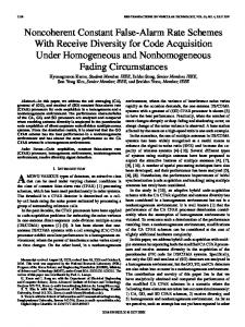
OFDM
CE-OFDM
Fig. 1. The CE-OFDM waveform is derived from mapping the conventional OFDM signal to the unit circle. For this example the modulation index is 2πh = 0.7. 5 Instantaneous signal power
I. I NTRODUCTION
⇒
OFDM CE-OFDM
4 3 2 1 00
0.2
0.4 0.6 Normalized time
0.8
1
Fig. 2. This figure compares the instantaneous power of a conventional OFDM signal, which has large fluctuations, to a CE-OFDM signal which has constant envelope power.
It is shown that with the introduction of memory, CE-OFDM is made phase-continuous and, consequently, has a more compact spectrum. An additional bonus of the noncoherent receiver is it demodulates continuous phase CE-OFDM signals with no added complexity. II. CE-OFDM S IGNAL D ESCRIPTION The CE-OFDM signal can be viewed as a mapping of the OFDM signal onto the unit circle, as shown in Fig. 1. The resulting signal has a constant envelope, thus a 0 dB PAPR, as depicted in Fig. 2.
100 CE-OFDM: w/ Memory w/o Memory OFDM
(a) L = 1
(b) L = 100
Fig. 3. Continuous phase CE-OFDM signal samples on the complex plane. The modulation index is 2πh = 0.7. This figure illustrates that with L = 1 signaling interval, a little less than one-third of the unit circle is used for mapping; viewing L = 100 intervals shows that the entire circle is used.
Fractional out-of-band power
10−1
2πh 0.7
10−2 10−3
0.5 0.3
10−4 0.1
10−5 10−6
The baseband representation of the CE-OFDM waveform is s(t) = Aejφ(t) ,
(1)
where A is the amplitude and the phase, φ(t), is the OFDM waveform φ(t) = 2πhCN m(t), (2) where m(t) =
∞ X N X
n=−∞ k=1
In,k qk (t − nT ).
(3)
The modulation index is h; CN is a normalizing constant; and m(t) is a real-valued OFDM waveform where N is the number of subcarriers, {In,k = ±1} represent binary data symbols, T is the signaling interval3 , and {qk (t)} represent the set of subcarrier waveforms, expressed as (0 ≤ t < T ; k ≤ N2 ) cos 2πkt/T qk (t) = sin 2π(k − N/2)t/T (0 ≤ t < T ; k > N2 ) (4) 0 (otherwise). Notice that the subcarriers are full-wave, orthogonal cosine and sine functions. Such an OFDM waveform can be generated by taking the real part of an discrete Fourier transform (DFT)4 . The normalizing constant CN is set to r 2 . (5) CN = N Consequently, the phase variance is " Z # T 1 σφ2 = E φ2 (t)dt T 0 Z N N (2πh)2 2 T X X = E [Ik Il ] qk (t)ql (t)dt (6) T N 0 k=1 l=1 N Z (2πh)2 2 X T 2 qk (t)dt = (2πh)2 , = T N 0 k=1
3 The
guard time, Tg , is excluded from this discussion since it relates to issues—namely frequency-selective fading—which are beyond the scope of this paper. 4 This is equivalent to taking a 2N -point DFT of a conjugate symmetric vector. In [10] both full-wave and half-wave sinusoids are studied.
10−7 0
0.5
1 1.5 Normalized frequency f Tb
2
Fig. 4. The fractional out-of-band power of CE-OFDM signals for various modulation index. The smaller the modulation index, the more spectrally contained the signal. Continuous phase CE-OFDM signals (those with memory) have lower out-of-band power.
thus independent of the number of subcarriers N . During each signaling interval, the bit energy is Eb =
A2 T , N
(7)
and the bit time is
T . (8) N To reduce adjacent channel interference, the CE-OFDM signal is made phase-continuous with the introduction of memory. The phase signal, as defined by (2), has phase jumps at each signaling interval boundary. By including memory terms, {θn }, these jumps are eliminated and the resulting CEOFDM phase signal is Tb =
φ(t) = θn + 2πhCN
N X
k=1
In,k qk (t − nT ),
(9)
for nT ≤ t < (n + 1)T , where θn = φ(nT − �) − φ(nT + �),
� → 0.
(10)
Therefore θn is a function of all data symbols during and prior to the nth signaling interval. The first consequence of continuous phase CE-OFDM is shown in Fig. 3. Viewing L = 1 signaling interval, a little less than one-third of the unit circle is used for mapping. But viewing signal samples for L = 100 intervals, Fig. 3(b) shows that the entire circle is used. This illustrates that the distribution of {θn } spans the interval [0, 2π). The second consequence of continuous phase operation is shown by the fractional out-of-band power curves in Fig. 4. The CE-OFDM signals with memory are shown to have lower out-of-band power for f Tb > 0.5. Notice that the modulation
Transmitter OFDM Mod
Channel
exp(·)
PA
αejφ0 n(t) Receiver A/D
FIR
arg(·)
unwrap
OFDM Demod
Fig. 5. Simplified block diagram of CE-OFDM system. The exp(·) block transforms the OFDM signal to a constant envelope signal, minimizing the nonlinear effects of the PA; the “unwrap” block makes the receiver operate noncoherently; and the FIR improves the performance of the arg(·) block.
index controls the spectral containment. For example, at normalized frequency f Tb = 0.5 the spectral containment of the 2πh = 0.1 signal is better than 99.99%; for the 2πh = 0.5 signal, the containment is 99%. Compared to the conventional OFDM signal, the CE-OFDM spectrum has better containment at all frequencies when 2πh ≤ 0.5. For the 2πh = 0.7 signal, the containment is better for all frequencies except the range 0.5 < f Tb < 0.85. The CE-OFDM signal could be filtered (which will result in a non-zero PAPR) but this topic isn’t considered for this paper. A potential problem with the continuous phase operation is the need to determine the set of memory terms, {θn }, at the receiver. As shown in the next section, the noncoherent CE-OFDM receiver circumvents this issue. III. N ONCOHERENT R ECEIVER
IN
FADING C HANNEL
Figure 5 shows a simplified block diagram of the CE-OFDM system. The exp(·) block represents the phase modulator at the transmitter and arg(·) represents the phase demodulator at the receiver. This figure illustrates how CE-OFDM can be considered a “transform technique”: the OFDM signal is transformed prior to the PA, then the inverse transform is performed at the receiver prior to OFDM demodulation. The channel is comprised of the complex additive Gaussian noise term n(t), which has bandwidth Bn and spectral height N0 , and the multiplicative fading term αejφ0 . Four channels are considered: 1) Coherent AWGN: α = 1, φ0 = 0. 2) Noncoherent AWGN: α = 1, φ0 ∈ [0, 2π)5 . 3) Rayleigh fading: α Rayleigh distributed, φ0 ∈ [0, 2π). 4) Ricean fading: α Rice distributed, φ0 ∈ [0, 2π). The received signal is r(t) = αejφ0 s(t) + n(t).
(11)
The angle of the received signal is arg[r(t)] = θn + 2πhCN
N X
k=1 5 “φ
0
In,k qk (t − nT ) + φ0 + ξ(t),
for nT ≤ t < (n + 1)T , where ξ(t) represents the nonlinear “additive” noise term. As described in [10], the power density spectrum of ξ(t), conditioned on high SNR and low modulation index, is Φξξ (f ) ≈ N0 /A2 over the in-band signal frequency range. The “OFDM Demod” block in Fig. 5 is comprised of N matched-filters, one for each subcarrier. The kth matched-filter computes the correlation6 Z (n+1)T arg[r(t)]qk (t − nT )dt = Sn,k + Nn,k + Θn,k , (13) nT
where the signal term is Z (n+1)T N X In,l ql (t − nT )qk (t − nT )dt Sn,k = 2πhCN nT
l=1 p = In,k × 2πh 1/2N,
and the noise term is Z Nn,k =
(14)
(n+1)T
nT
ξ(t)qk (t − nT )dt.
(15)
The third term, Θn,k , takes into account the channel phase and the memory term: Z (n+1)T Θn,k = [φ0 + θn ]qk (t − nT )dt. (16) nT
But since qk (t) has an integer number of oscillations over [0, T ], Θn,k = 0. (17) In other words, the presence of the (unknown) phase shift φ0 +θn has no impact on the demodulation of the data symbols since only non-DC subcarriers are modulated. This makes CEOFDM naturally noncoherent. Ideally the output of the arg(·) block in Fig. 5 is comprised of samples of (12). However, due to the phase offset terms, the received CE-OFDM phase signal will cross the π radian boundary. The resulting phase ambiguities cause phase jumps at the output of the arctangent calculation which severely degrades performance. Thus the motivation for the phase unwrapper: the “unwrap” block adds multiples of 2π radians as appropriate to remove jumps greater than π radians [14]. In noise-free operation, the phase unwrapper works perfectly. However, when noise is added, phase unwrapping is susceptible to errors. Oversampling, i.e. sampling at a rate Fs = bN/T , where b > 1 is the oversampling factor, can improve performance of the phase unwrapper. But this increases the noise power7 (σn2 = N0 Bn = N0 Fs ), which, in turn, degrades the performance of the arg(·) block. The purpose of the finite impulse response (FIR) filter is to limit out-of-band noise power. It has been
(12)
∈ [0, 2π)” denotes “uniformly distributed over the range [0, 2π)”.
6 For convenience, the correlator is viewed as a continuous-time integral. In practice this is computed as a discrete-time summation. 7 Sampling n(t) at the sampling rate F is assumed to yield independent s noise samples; therefore, Bn = Fs .
100
100 2πh = 0.1 2πh = 0.2 2πh = 0.3 2πh = 0.6 Approx (19)
Coherent Noncoherent Approx (18)
10−2
10−2 BER
10−1
BER
10−1
2πh
10−3
0.7
0.5
0.3
0.2
10−3
0.1
10−4
10−4
10−5 0
5
10
15 Eb /N0 (dB)
20
25
30
Fig. 6. Additive white Gaussian noise performance for coherent and noncoherent CE-OFDM. This figure demonstrates that phase coherence at the receiver isn’t important for 2πh ≤ 0.5. For larger modulation index, the system reaches performance limitations.
found that the oversampling factor b = 8 with a length M = 11 Hamming window filter, having a normalized cut-off frequency fcut = 0.2 cycles per sample [15, ch. 8], delivers good results. IV. A NALYTICAL BER A PPROXIMATIONS As shown in [10], the coherent AWGN performance of CEOFDM using binary data symbols is approximated as √ (18) BER ≈ Q (a γ) , √ where a = 2πh 2 and γ = Eb /N0 . Therefore, the performance for Rayleigh flat fading is approximated as [16, p. 101] s ! 1 a2 γ¯ /2 BER ≈ 1− , (19) 2 1 + a2 γ¯ /2 where γ¯ = E(α2 )γ is the average SNR per bit. For Ricean flat fading [16, p. 102] Z 1 π/2 (1 + K) sin2 θ BER ≈ × π 0 (1 + K) sin2 θ + a2 γ¯ /2 (20) � � Ka2 γ¯ /2 dθ, exp − (1 + K) sin2 θ + a2 γ¯ /2 where K is the Ricean factor [17], i.e., the ratio between the line-of-sight (LOS) component and the scattered component [18]. V. S IMULATION R ESULTS The simulation results are performed with an oversampling factor b = 8 and, as describe above, with the M = 11 length Hamming window FIR with fcut = 0.2. The code used to generate all the figures in this paper can be found in [19].
10−5 0
10
20 30 Eb /N0 (dB)
40
50
Fig. 7. Performance of noncoherent CE-OFDM receiver for Rayleigh flat fading. The analytical approximation, (19), closely matches simulation results for 2πh ≤ 0.3. For 2πh = 0.6 the limitation of the receiver is demonstrated.
Figure 6 shows the AWGN performance for both coherent and noncoherent reception. For 2πh ≤ 0.5, phase coherence at the receiver is shown to be unimportant: the coherent and noncoherent systems have equivalent performance for Eb /N0 ≥ 8 dB. For the larger modulation index case of 2πh = 0.7 the noncoherent system is shown to have a 1 dB degradation compared to the coherent system. In which case, the analytical approximation, (18), is shown to be overly optimistic. This demonstrates the limitation of the nonlinear CE-OFDM receiver. For larger values of modulation index, the front-end phase demodulator—a nonlinear device—fails to perform properly, passes additional (non-AWGN) noise to the matched-filter bank, and the resulting performance is worse than the analytical approximation predicts. Figure 7 shows the performance of the noncoherent receiver for Rayleigh flat fading. Simulation results are shown to closely match (19) for 2πh ≤ 0.3. For the 2πh = 0.6 case, the simulation results is about 3 dB worse than the analytical approximation. As for the AWGN case, this is an illustration of the phase demodulator limitation. The Rayleigh fading exacerbates the problem. Figures 8 and 9 show the performance of the receiver for Ricean flat fading channels. The Ricean factors are K = 0 dB (equal LOS and scatter components), K = 3 dB (the LOS has 2× more power than the scatters), K = 10 dB (LOS has 10× more power), and K = 20 dB (LOS has 100× more power). The K = 0 dB case yields performance slightly better than the Rayleigh channel; the K = 20 dB channel is essentially equivalent to noncoherent AWGN. For the 2πh = 0.3 example shown in Fig. 8, the simulation results are in good agreement with the analytical approximation in (20), especially for the K = 10 dB and K = 20 dB channels. For the 2πh = 0.6 case in Fig. 9, the K = 20 dB channel results in good agreement
100
100 K = 0 dB K = 3 dB K = 10 dB K = 20 dB Approx (20)
10−1
K = 0 dB K = 3 dB K = 10 dB K = 20 dB Approx (20)
10−1
BER
10−2
BER
10−2
10−3
10−3
10−4
10−4
10−5 0
10
20 30 Eb /N0 (dB)
40
50
10−5 0
10
20 30 Eb /N0 (dB)
40
50
Fig. 8. Performance of noncoherent CE-OFDM receiver with Ricean flat fading channels. The modulation index is 2πh = 0.3. Simulation results are in good agreement with (20), especially for K = 10 dB and K = 20 dB channels.
Fig. 9. Performance of noncoherent CE-OFDM receiver with Ricean flat fading channels. The modulation index 2πh = 0.6. The analytical approximation is shown to be in good agreement with simulation results for K = 20 dB at high SNR. For the other cases, (20) is overly optimistic.
for high SNR; for the other channels, (20) is overly optimistic for the same reasons already discussed.
[5] H. Ochiai, “A Novel Trellis-Shaping Design With Both Peak and Average Power Reduction for OFDM Systems,” IEEE Trans. Commun., vol. 52, no. 11, pp. 1916–1926, Nov. 2004. [6] E. Costa, M. Midrio, and S. Pupolin, “Impact of Amplifier Nonlinearities on OFDM Transmission System Performance,” IEEE Commun. Lett., vol. 3, no. 2, pp. 37–39, Feb. 1999. [7] D. Dardari, V. Tralli, and A. Vaccari, “A Theoretical Characterization of Nonlinear Distortion Effects in OFDM Systems,” IEEE Trans. Commun., vol. 48, no. 10, pp. 1755–1764, Oct. 2000. [8] P. Banelli and S. Cacopardi, “Theoretical Analysis and Performance of OFDM Signals in Nonlinear AWGN Channels,” IEEE Trans. Commun., vol. 48, no. 3, pp. 430–441, Mar. 2000. [9] S. C. Thompson, J. G. Proakis, and J. R. Zeidler, “Binary OFDM Phase Modulation,” in Proc. IEEE MILCOM, Boston, Oct. 2003. [10] S. C. Thompson, A. U. Ahmed, J. G. Proakis, and J. R. Zeidler, “Constant Envelope OFDM Phase Modulation: Spectral Containment, Signal Space Properties and Performance,” in Proc. IEEE MILCOM, Monterey, Nov. 2004. [11] C.-D. Chung and S.-M. Cho, “Constant-Envelope Orthogonal Frequency Division Multiplexing Modulation,” in Proc. APCC/OECC ’99, vol. 1, Beijing, Oct. 1999, pp. 629–632. [12] J. Tan and G. L. St¨uber, “Constant Envelope Multi-Carrier Modulation,” in Proc. IEEE MILCOM, vol. 1, Anaheim, Oct. 2002, pp. 607–611. [13] X. Wang, T. T. Tjhung, and Y. Wu, “On the SER and Spectral Analyses of A-Law Companding Multicarrier Modulation,” IEEE Trans. Veh. Technol., vol. 52, no. 5, pp. 1408–1412, Sept. 2003. [14] GNU Octave. [Online]. Available: http://www.octave.org/ [15] J. G. Proakis and D. G. Manolakis, Digital Signal Processing: Principles, Algorithms, and Applications, 3rd ed. Upper Saddle River, NJ: Prentice Hall, 1996. [16] M. K. Simon and M.-S. Alouini, Digital Communication over Fading Channels. New York: John Wiley & Sons, Inc., 2000. [17] C. Tepedelenlioglu, A. Abdi, and G. B. Giannakis, “The Ricean K Factor: Estimation and Performance Analysis,” IEEE Trans. Wireless Commun., vol. 2, no. 4, pp. 799–810, July 2003. [18] M. P¨atzold, Mobile Fading Channels. West Sussex, England: John Wiley & Sons, 2002. [19] S. C. Thompson, “Code for ‘Noncoherent Reception of Constant Envelope OFDM in Flat Fading Channels’.” [Online]. Available: http://elsteve.com/papers/
VI. C ONCLUSION In this paper, a noncoherent receiver is presented for constant envelope OFDM. CE-OFDM is shown to be a naturally noncoherent modulation. The matched-filter bank following the phase demodulator eliminates the effect of unknown phase shifts caused by the channel or that result from continuous phase operation. The performance of CE-OFDM in noncoherent Rayleigh and Ricean flat fading channels is studied. It is shown that, for small modulation index and high SNR, simulation results are in good agreement with analytical approximations. VII. ACKNOWLEDGMENTS The first author would like to thank Mike Geile and Mark Fischer (Nova Engineering, Cincinnati, OH) for technical discussions and suggesting Fig. 3. R EFERENCES [1] M. Friese, “On the Achievable Information Rate with Peak-PowerLimited Orthogonal Frequency-Division Multiplexing,” IEEE Trans. Inform. Theory, vol. 46, no. 7, pp. 2579–2587, Nov. 2000. [2] V. Tarokh and H. Jafarkhani, “On the Computation and Reduction of the Peak-to-Average Power Ratio in Multicarrier Communications,” IEEE Trans. Commun., vol. 48, no. 1, pp. 37–44, Jan. 2000. [3] J. Tellado, L. M. C. Hoo, and J. M. Cioffi, “Maximum-Likelihood Detection of Nonlinearly Distorted Multicarrier Symbols by Iterative Decoding,” IEEE Trans. Commun., vol. 51, no. 2, pp. 218–228, Feb. 2003. [4] M. Sharif and B. Hassibi, “On Multicarrier Signals Where the PMEPR of a Random Codeword is Asymptotically log n,” IEEE Trans. Inform. Theory, vol. 50, no. 5, pp. 895–903, May 2004.