JOURNAL OF PROPULSION AND POWER Vol. 17, No. 5, September– October 2001
Nonlinear Control of a Reusable Rocket Engine for Life Extension Carl F. Lorenzo¤ NASA John H. Glenn Research Center at Lewis Field, Cleveland, Ohio 44135 and Asok Ray† and Michael S. Holmes‡ The Pennsylvania State University, University Park, Pennsylvania 16802 The conceptual development and a design methodology are presented for life-extending control where the objective is to achieve high performance and structural durability of complex dynamic systems. A life-extending controller is designed for a reusable rocket engine via damage mitigation in both the fuel (H2 ) and oxidizer (O2 ) turbine blades while satisfying the dynamic performance requirements of the combustion chamber pressure and O2 /H2 mixture ratio. The design procedure makes use of a combination of linear and nonlinear techniques and also allows adaptation of the life-extending controller module to augment a conventional performance controller of the rocket engine. The nonlinear part of the controller is designed by optimizing selected parameters in a prescribed dynamic structure of damage compensation.
Nomenclature b D DP s W ±cyc ¾ ¾a ¾m ¾ 0f Ä
A
= = = = = = = = = = =
development of a life-extending control (LEC) system for rocket engines via damage mitigation in both the fuel (H2 ) and oxidizer (O2 ) turbine blades. The design approach presented in this paper allows adaptation of the LEC feature to augment a conventional performance controller of a rocket engine.
fatigue strength exponent (dimensionless) fatigue damage (normalized) rate of fatigue damage, s 1 Laplace transform variable, s 1 weighting transfer function damage increment in one stress cycle tensile stress, ksi stress amplitude in a stress cycle, ksi mean stress in a stress cycle, ksi fatigue strength coef cient, ksi turbine shaft speed, rad/s
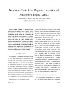
Description of the Reusable Rocket Engine A functionaldiagram for the operation and control of the reusable rocket engine under consideration is presented in Fig. 1. The propellants, namely, liquid hydrogen (H2 ) fuel and liquid oxygen (O2 ), are individually pressurized by separate closed-cycle turbopumps. Pressurized cryogenic fuel and oxygen are pumped into two highpressure preburners that feed the respective turbines with fuel-rich hot gas. The fuel and oxidizer turbopump speeds and, hence, the propellant ow into the main thrust chamber are controlled by the respective preburner pressures. The exhaust from each turbine is injected into the main combustion chamber, where it burns with the remaining oxidizer and is expanded through the rocket nozzle to generate thrust. The oxygen ow into each of the two preburners are independently controlled by the respective servocontrolled valves. The plant outputs of interest are the O2 /H2 mixture ratio and main thrust chamber pressure, which are closely related to the rocket engine performance in terms of speci c impulse, thrust ratio, and combustion temperature. A thermo uid-dynamic model of the rocket engine has been formulated for plant performance analysis and control systems synthesis.1 Standard lumped parameter methods have been used to approximate the partial differential equations describing mass, momentum, and energy conservation by a set of rst-order differential equations. The plant model is constructed by causal interconnection of the primary subsystem models such as main thrust chamber, preburners, turbopumps, fuel and oxidizer supply header, and xed nozzle regenerationcooling. The plant model has 18 state variables, 2 control inputs, and 2 controlled outputs.
Introduction
MAJOR task in the control and operation of reusable rocket engines is to achieve a tradeoff between dynamic performance and structural durability of critical components. A rocket engine has a number of critical components that operate close to mechanical design limits. These components often typify behavior of the remaining components and, hence, are indicators of the effective service life of the engine. For example, critical components of the space shuttle main engine (SSME) that are subjected to a variety of damage modes, for example, creep and fatigue, and potentially limit its service life include the following: blades of the fuel (H2 ) and oxidizer (O2 ) turbines, combustion chamber and nozzle wall, and injector tubes. Fatigue damage in injector tubes was once a source of engine failure. However, this problem has reportedly been solved by appropriate selection of materials in later versions of the SSME. Tensile rupture of the coolant channel ligaments in the combustion chamber and rocket nozzle is primarily caused by creep and creep ratcheting due to the plasticity of copper (and copper alloys) at high temperatures (for example, »1200± R). Fatigue damage in fuel and oxidizer turbine blades is primarily caused by stress cycling during startup, shutdown, and transient operations of a rocket engine. Fatigue damage in the turbine blades is one of the most serious causes for engine failure. This paper focuses on the conceptual
LEC System The concept of LEC was introduced by Lorenzo and Merrill.2 Subsequently, a growing body of literature has emerged for feedforward3;4 and feedback control5 of rocket engines for life extension. Although the life-extending control technology was developed initially for rocket engines, it has broad applications to other systems such as fossil-fueled power plants6 and mechanical structures,7 where both dynamic performance and structural durability are critical issues. The design approachpresented in this paper allows adaptationof the LEC feature to augment a conventionalperformance controller of a rocket engine.
Received 8 January 2000; revision received 19 March 2001; accepted for c 2001 by the American Institute of publication 5 April 2001. Copyright ° Aeronautics and Astronautics, Inc. All rights reserved. ¤ Distinguished Research Associate. † Professor of Mechanical Engineering;
[email protected]. Associate Fellow AIAA. ‡ Graduate Research Assistant, Mechanical Engineering; currently Research Engineer, Lockheed Martin Corporation, Moorestown, NJ. 998
999
LORENZO, RAY, AND HOLMES
Design of the Linear Performance Controller
Fig. 1
Schematic diagram of reusable bipropellant engine.
This section presents the design of a sampled-data performance controller (inner loop) for the reusable rocket engine by using the H1 (or induced L 2 norm to L 2 norm) controller synthesis technique.8 This controllerdesign method minimizes the worst-case gain between the energy of the exogenous inputs and the energy of the regulated outputs of a generalized plant which will be constructed subsequently.Bamieh and Pearson9 proposed a solution to the induced L 2 norm controller synthesis problem for application to sampled-data systems. This design procedure has subsequently been incorporated as the function sdhfsyn in the MATLAB ® mutools toolbox.10 The performancecontrollerneeds to have very good low-frequencydisturbancerejectioncapabilitiesto prevent the damage controller output u dam from causing a long settling time in the plant outputs. Figure 3 shows the con guration of the generalizedplant for synthesis of an induced L 2 norm controller.8;10 The controllersynthesis is based on a plant model of the rocket engine with two inputs (fuel preburner oxidizer valve position and oxidizer preburner oxidizer valve position) and two outputs (main thrust chamber hot-gas pressure and O2 /H2 mixture ratio). The plant model is obtained by rst linearizing the 18-state nonlinear model of the rocket engine at a combustion pressure of 2550 psi (17.58 MPa) and an O2 /H2 ratio of 6.02. The bandwidth of the valves is assumed to be nonlimiting for this study. The pressure 2550 psi (17.58 MPa) is chosen for linearization because the controller is required to operate in the range 2100– 3000 psi (14.48– 20.69 MPa). After linearization,the 18-state linear model is reduced to a 13-state linear model for the controller design via Hankel model-order reduction (see Ref. 8). A comparison of Bode plots reveals that reducing the 18-state model to 13 states does not signi cantly alter the input– output characteristicsof the original model. Because the induced L 2 norm controller synthesis procedure being used here requires a strictly proper generalized plant model, the problem of a nonzero direct coupling matrix (in the state-variable representation) is circumvented by ltering the outputs of the controller by a rst-order lter with a very-highfrequency pole at 105 rad/s: W lter .s/ D 104 =.s C 104 /
Fig. 2 Damage mitigating control system and of ine optimizer.
Figure 2 shows the architecture of the two-tier LEC system. The performance controller in the inner loop is designed to achieve a high level of dynamic performance. In the typical situation, with a linearized plant, that is, rocket engine, model, this controller can be designed using control synthesis techniques such as H1 -based ¹ synthesis to assure stability and performance robustness.8 The combination of plant dynamics and the performance controller in the inner loop becomes the augmented plant for the nonlinear damage controller design in the outer loop. The essential elements of the damage controller in the outer loop are 1) a structural model that uses appropriate plant outputs to estimate the load conditions, for example, stress at the critical locations; 2) a time-domain damage model that uses the load conditionsto determine the damage rate and accumulation at the critical point(s); and 3) the damage controller, which is designed to reduce the damage rate and accumulation at the critical points, speci cally under transient operations where the time-dependentload on the stressed structureis controllable.Salient features of this controller design approach are 1) the controller design proceduresin the two individualloops are decoupledand can be separately carried out individually by standard commercially available software; 2) unlike other reported design approaches,3;4;6 there is no need to determine an optimal feedforward control sequence that is sensitive to plant modeling uncertainties and variations in the initial conditions; and 3) for some control applications, such as military aircraft, the LEC feature can be activated or deactivated at the operator’s discretion.
(1)
The input multiplicative con guration is chosen to represent the plant model uncertainties due to parametric errors and unmodeled high-frequencydynamics. The sampler and zero-order hold associated with the controller are implicit for robust stability of the inner loop in the control architecture of Fig. 2. Each of the two components of the frequency-dependent disturbance weight Wdel in the generalized plant model of Fig. 3 is chosen to be W del .s/ D .s C 1/=.s C 10/
(2)
which implies that the amount of plant uncertainty is estimated as being approximately 10% at low frequencies and 100% at high frequencies.The uncertaintymodel is constructedbasedon the assumptions of the rocket engine design and operation and can be updated as additional analytical or experimental data become available. Because the plant model is validated with steady-state design data, it is more accurate in the low-frequency range. The plant model is a nite-dimensional lumped-parameter representationthat may not capture the dynamics of high-frequency modes. This leads to the presence of a larger amount of uncertainty in the high-frequencyregion of the model as compared to the uncertaintyat low frequencies. The frequency-dependentperformance weight Wperf consists of two components: Wpress , which penalizes the tracking error of combustion chamber pressure,and WO2 =H2 , which penalizesthe tracking error of the O2 /H2 ratio. The frequency-dependent control signal weight Wcont consists of two components: WH2 , which penalizes the fuel preburner oxidizer valve position, and WO2 , which penalizes the oxidizer preburner oxidizer valve position. The objectives of these control signal weights are 1) prevention of large oscillations in the feedback control signal that may cause valve saturationand 2) reduction of valve wear and tear due to high-frequencymovements.
1000
LORENZO, RAY, AND HOLMES
Fig. 3
Generalized plant for linear controller synthesis.
The parameters of both performance weights and control signal weights are initially selected based on the control system performance requirements and the knowledge of the plant dynamics. Subsequently, the parameters are ne tuned based on the time-domain responses of the simulation experiments. For this design, the performance weights are Wpress .s/ D 4[.s C 1:75/=.s C 1/]
(3)
WO2 =H2 .s/ D 4000[.s C 0:5/=.s C 0:1/]
(4)
The control weights for the H2 and O2 valves are chosen to be identical: WH2 .s/ D 1200[.s C 0:75/=.s C 10/]
(5)
WO2 .s/ D 1200[.s C 0:75/=.s C 10/]
(6)
Each of the two components of the frequency-dependentreference signal weight Wref in Fig. 3 is chosen to be Wref .s/ D 0:5=.s C 0:5/
(7)
With the use of the generalized plant of Fig. 3, a sampled-data controller is designed that is optimal in the induced L 2 norm sense. As guaranteedby the design method employed,the controllerhas 21 states, which is the same as the number of states in the generalized plant model, which consists of the reduced-order plant model (13 states), the control signal lters (2 states), the performance weighting matrix (2 states), the referencesignalweightingmatrix (2 states), and the controlsignalweightingmatrix (2 states). The controllerprovides acceptablereferencesignaltrackingfor the plant without using a large amount of control effort. It is found that reducing the order of the sampled-data controller from 21 states to 15 states causes no signi cant change in the controller dynamics from an input– output point of view. Therefore, this reduction causes no noticeable difference in the simulation results produced by the 21-state and 15-state controllers. The 15-state controller is used in what follows.
Fatigue Damage Modeling Damage modeling is a critically important aspect of LEC. The damage model is continuous-time based for use in the controller design procedure as well for the implementation of the controller itself. Because the model is embedded in the LEC, it should be as mathematically and/or computationally simple as possible, while representing the damage rate with suf cient accuracy for control purposes. The implication is that the absolute level of the damage rate may not be so important as the structure of the damage equation (or formulation); that is, the nonlinearity must be properly described. Furthermore, computationalsimplicity becomes especially important when optimization is used in the design process. A wide variety of damage mechanismsexist in the reusable rocket engine including fatigue and high-temperaturecreep. The objective of this paper is to establish a viable design method for LEC systems that includes the nonlinear damage characteristicsof structural materials. Fatigue damage of the oxygen and hydrogen turbopump turbine blades is selected as the damage mechanism (and critical locations). This type of damage is highly nonlinear, and damage
controller design techniques that work for it will likely be adequate for other damage mechanisms as well. The fatigue damage model used in the controller design assumes that damage only occurs during tensile loading. Three speci c damP (The mateage rate models may be used to estimate damage rate D. rial constants used in this section are de ned in the Nomenclature.) For the case of zero mean tensile stress, P /D D.t
2 b¾ 0f
³
¾ ¾ 0f
´
.1 C b/=b
d¾ ; dt
¾ > 0;
¾ increasing (8)
where ¾ is the instantaneous stress and the fatigue strength coef cient ¾ 0f and the fatigue strength exponent b are material constants. When the mean stress ¾m is not zero, the damage rate is determined as P D.t/ D
2 b
³
´
1 ¾ 0f
for
1= b
¾m
.¾
¾m /
.1 C b/=b
d¾ dt
¾ increasing (9)
¾ ¸ ¾m ¸ 0;
Finally, under certain conditions, it may be desirable to use a maximum damage rate equation, namely, .1 C b/ =b d¾ P /max D 2.1 C b/ D.t ; ¾ 0f ¾ dt
for
¾ 0f > ¾m ¸ 0
(10) This form provides an estimate of the instantaneous damage rate that is greater than the damage rate for any mean stress and is a conservative estimate for conditions when the LEC approach is to reduce peak stresses and mean stress is dif cult to estimate. For the current application, it will be seen that the damage mitigation is derived from reducing the mean stress on the turbine blades. Therefore, the damage rate in Eq. (9) has been integrated to give the damage increment in one stress cycle as ±cyc D 2[¾a =.¾ 0f
¾m /]
1 =b
(11)
The followingmaterial parametershave been selected for the turbine blade material under consideration: ¾ 0f D 223:6 ksi (1541.7 MPa) and b D 0:0858. The fatigue strength coef cient was adjusted by a factor of 0.82 to best match a more detailed model. The damage rate is calculated from the relation DP D [¾a =.¾ 0f
¾m /]
1=b
Ä
(12)
where Ä is the frequencyof vibrationof the blades in units of radian per second. This model estimates fatigue damage online and of ine for control and optimization, respectively.
Design of the Nonlinear Damage Controller The outer damage control loop is a cascaded combination of a structural estimator, a nonlinear fatigue damage model for the turbine blades, and a linear dynamic lter acting as the damage
1001
LORENZO, RAY, AND HOLMES
controller. The parameters of the dynamic lter are optimized to reduce the damage rate and accumulation at the critical points, that is, fuel and oxidizer turbine blades, speci cally under transient operations where the time-dependent load on the stressed structure is controllable. The nonlinear damage model is a simpli ed representation of the material behavior so that it can be incorporated in the outer control loop for real-time execution. The dynamic part of the nonlinear damage controller is designed as a discrete-time linear structure by directly optimizing the elements of its system, that is, A, B, C, and E , matrices in the statevariable representation.To decrease the number of parameters to be optimized,we have chosen a canonicalform in which the A matrix is constrainedto be a diagonal matrix with distinct real elements. This is equivalentto constrainingthe damage controllerto having distinct real eigenvalues. Repeated and/or complex poles can be included at the expense of computational complexity. For a damage controller with m inputs, p outputs, and n states, the number of parameters to be optimized is n (for the diagonal n £ n A matrix) C nm (for the n £ m B matrix) C pn (for the p £ n C matrix) C pm (for the p £ m E matrix) D n.1 C m C p/ C pm parameters.Note that other canonical forms of state-space representation could be applicable. The parameters of the linear dynamic lter are identi ed by minimizing a cost functional using nonlinear optimization. For each evaluation of the cost functional, a nominal computer simulation must be performed. The cost functional is evaluated by the simulation, and the simulation results are a function of the current damage controller chosen by the optimization routine. Because damage controllers designed using this method are directly based on the maneuver used in the optimization process, the maneuver should be chosen to be broadly representative of all plant operation. The resulting damage controller is then validated by examining the results of various other typical maneuvers that the plant is expected to perform with this damage controller in the damage feedback loop. The simulation on which the design of the damage controller is based is a rampup of the main thrust chamber hot-gas pressure from a level of 2700– 3000 psi (18.62– 20.69 MPa) at a rate of 3000 psi/s, followed by a steady state at the nal 3000 psi pressure for 500 ms, as shown in Fig. 4. The O2 /H2 mixture ratio for this simulation is to be kept at a constant value of 6.02. After each simulation is performed, data representing the results of the simulation is sent to the cost functional subroutine. These data consist of samples of the chamber pressure, the O2 /H2 mixture ratio, the damage rate in the O2 turbine blade, and the damage rate in the H2 turbine blade at every T D 0:002 s. Because the duration of the simulation is 0.6 s and each trajectory is sampled every T D 0:002 s, there is a total of N D 300 samples sent to the cost functional subroutine for each of the four trajectories listed earlier. In addition, the value of accumulated damage for the O2 and H2 turbines at time t D 0:6 s is also used for the calculation of the value of the cost functional. The multiobjective cost functional includes the effects of both dynamic performance,that is, referencesignaltracking,and damage in the turbine blades: J
tot
DJ
perf
CJ
dam
(13)
The performancepart of the cost functional J perf is the sum of penalties on the following two errors.
Fig. 4
Reference trajectory for chamber pressure.
1) Tracking error of the main thrust chamber hot gas pressure: Jpress D
N 1 X
Á Q press
ref ypress .kT /
ypress .kT /
!2 (14)
ref .kT / 1 C ypress
kD1
Á ss Jpress D Q ss press
ref ypress .N T /
ypress .N T /
!2
ref .N T / C 1:0 ypress
(15)
ref where ypress .²/ is the reference trajectory for the thrust chamber pressure. 2) Tracking error of the O2 /H2 mixture ratio:
JO2 =H2 D where g.kT / D
8Á > < yO2 =H2 .kT / > :
N 1 X
(16)
Q O2 =H2 g.kT /
k D1
yOref2 =H2
!2 if
1 C yOref2 =H2 0
Á JOss2 =H2 D Q ss O2 =H2
-lim yO2 =H2 .kT / ¸ yOnon 2 =H 2
otherwise yO2 =H2 .N T /
yOref2 =H2
1 C yOref2 =H2
!2
(17) (18)
where the reference yOref2 =H2 for O2 /H2 mixture ratio is held constant -lim is set at 6.04. at 6.02 and its nominal limit yOnom 2 =H 2 The need for weighting the O2 /H2 mixture ratio is to prevent thermal excursion damage of the thrust chamber. This occurs as -lim as seen in mixture ratio increases above its nominal limit yOnom 2 =H 2 Eq. (17). The fatigue damage part of the cost functional J dam is the sum of the following penalties. 1) Damage rate in the O2 turbine blades: J DP O D 2
N X kD1
Q DP O DP O2 .kT /
(19)
2
2) Damage rate in the H2 turbine blades: J DP H D
N X
2
Q DP H DP H2 .kT /
(20)
2
kD1
3) Accumulated damage in the O2 turbine blades:
¡
J DO2 D Q DO2 DO2 .N T /
DO2 .0/
¢
(21)
4) Accumulated damage in the H2 turbine blades:
¡
J DH2 D Q DH2 DH2 .N T /
DH2 .0/
¢
(22)
Both the pressure and O2 /H2 ratio components of the cost functional have extra weight on the error at the nal sampling instant, (that is, the N th sample). Adjusting these extra weights is a means to control the steady state behavior of the simulation. Increasing ss the steady-state weights Q ss press and/or Q O2 =H2 tend to decrease the settling time of the control system. Also, because it is desired to -lim during transients, the keep the O2 /H2 mixture ratio below yOnom 2 =H 2 mixture ratio is penalized only if it exceeds 6.04 for samples 1 – N -1. The nal N th sample of the O2 /H2 ratio is penalized regardless of whether its value is above or below 6.04 because it is necessary for the O2 /H2 ratio to reach the referencepoint yOref2 =H2 in the steady state. The factor of 1.0 added in the denominator of Eqs. (14), (15), (17), and (18) is a convenient way to combine the features of absolute and relative error and is often used in practice.11 The accumulated damage and damage rate components of the cost functional do not contain an absolute value operator or squared
1002
LORENZO, RAY, AND HOLMES
terms because damage rate and accumulation are always positive. In the accumulated damage components [Eqs. (21) and (22)], the initial accumulated damage is subtracted from the nal damage at time N T D 0:6 s to penalize the damage accumulated during the maneuver. The initial fatigue damage for both the O2 and the H2 turbine blades is assumed to be D(0) D 0.1. Because the governing equations and the cost functional are nonlinear in nature, a nonlinear programming technique is used to identify the optimal parameters of the damage controller. Also, to evaluate the cost functional, a time consuming simulation must be performed. Therefore, a nonlinear programming technique known as sequential quadratic programming (SQP) is employed, which has the reputation of being able to ef ciently and successfully solve a wide range of nonlinear programming problems in which the evaluation of the cost functional is a computationally intensive procedure.12 An SQP FORTRAN software package developed by Gill et al.13 at Stanford University called NPSOL is utilized to design the damage controller. Interaction effects between the damage controller and the performance controller are minimized 1) by requiring a high level of dynamic performance through the cost functional for the nonlinear optimization of the damage controller and 2) by the inherent frequency separation of the high-frequency damage loop and the lower frequency performance loop. The following set of weights are found to produce an effective damage controller: Q press D 21:0; Q ss press
6
D 10 ;
Q DP O D 719:42 2
2 sensor outputs ( p D 2). Therefore, the number of parameters to be optimized is [n £ .1 C m C p/ C m £ p] D 79. It is found that, after designing the 15-state damage controller, reducing the number of controller states to ve via Hankel model order reduction does not signi cantly change the input– output characteristicsof the controller. Therefore, the results that follow are created by using the ve-state reduced-order damage controller. This implies that it could have been more ef cient to directly optimize a controller with 5 states instead of 15 states. Unfortunately, it is not known how to choose optimally the number of controller states a priori. The damage controller is designed based on a transient that takes the chamber pressure from 2700 psi (18.62 MPa) to 3000 psi (20.69 MPa) (see Figs. 5 – 10). Each plot displays two cases: no damage control, that is, u.k/ D u f b .k/ and with damage control, that is, u.k/ D u f b .k/ C u dam .k/. The chamber pressure trajectoriesfor the two cases are compared in Fig. 5. The damage controller causes a slower rise time, a longer settling time, and less overshoot in the chamber pressure transient. The damage controller also causes the O2 /H2 ratio to deviate further from the desired value of 6.02 than the case with no damage control, as seen in Fig. 6. However, the mixture ratio settles to 6.02 at steady state and remains within acceptable bounds throughoutthe duration of the simulation for both cases. The damage rate and accumulation plots for the rst 1 s of the 2700 psi (18.62 MPa) to 3000 psi (20.69 MPa) simulation are shown in Figs. 7 and 8. Table 1 summarizes the accumulated damage after this time interval for the two simulation cases, that is, with and without damage control, for the two turbine blades.
Q DP H D 5:31 £ 104 2
Q O2 =H2 D 2:6 £ 108 ;
Q DO2 D 3:60 £ 105
8 Q ss O2 =H2 D 2:6 £ 10 ;
Q DH2 D 2:66 £ 107
Stability of the Nonlinear Damage Control System Stability of the closed-loop system is the single most important requirement of any controller design. Whereas a necessary and suf cient condition for stability is easily obtained from the eigenvalues of the A matrix in nite-dimensional linear time-invariant systems, there is no such straightforward condition for stability of nonlinear and/or time-varying systems. Analytical methods that may be successful in proving the stability and absence of limit cycles in the closed loop damage control system include describing function and the absolute stability methods of Lur’e and Postnikov (see Ref. 14). The closed-loop damage control system is nonlinear due to the structure of the fatigue damage model in the outer feedback loop. The inner control loop is guaranteed to be robustly stable with respect to the speci ed uncertainty description. The damage control signal u dam in Fig. 2 acts as an exogenous disturbance to the inner loop. However, outer-loop stability is not guaranteed by of ine optimization for parameter identi cation. If the outer-loop controller is given limited authority, that is, if bounds are imposed on u dam , it will be unable to destabilize the inner-control loop, and the system response remains bounded, although this does not establish stability in the sense of Lyapunov. For example, there is no guarantee that phenomena such as limit cycling of the control signals will not occur. Further research is needed to explore nonlinear controller synthesis techniques11 to simultaneously satisfy the requirements of stability and performance in nonlinear LEC systems. However, from the perspectives of rocket engine control, outer-loop stability is not problematic because the total ight time is very limited, for example, »420 s. Extensive simulation experiments over this nite-time horizon of active engine operation show that the two-tier control system is stable without imposition of any bounds on the damage control signal u dam .
Fig. 5
Combustion chamber gas pressure (2700– 3000 psi).
Fig. 6 O2 /H2 mixture ratio (2700– 3000 psi).
Simulation Results and Discussion For the rocket engine under consideration,the damage controller is designed using 15 states (n D 15), 2 actuator inputs (m D 2), and
Fig. 7
Fatigue damage in H2 turbine blades (2700– 3000 psi).
1003
LORENZO, RAY, AND HOLMES
Table 1
Blade H2 O2
Fig. 8
Fig. 9
Damage after 1 s for 2700– 3000 psi simulation
Without damage control 1:13 £ 10 1:21 £ 10
5 3
With damage control 6:15 £ 10 3:45 £ 10
6 5
Table 2
Ratio
Blade
1.8 35.1
H2 O2
Fatigue damage in O2 turbine blades (2700– 3000 psi).
Damage after 1.2 s for 2100– 3000 psi simulation
Without damage control 2:46 £ 10 2:48 £ 10
5 3
With damage control 9:61 £ 10 7:01 £ 10
6 5
Ratio 2.6 35.4
Fig. 11
Fatigue damage in H2 turbine blades (2100– 3000 psi).
Fig. 12
Fatigue damage in O2 turbine blades (2100– 3000 psi).
Combustion chamber gas pressure (2100– 3000 psi).
Fig. 10
O2 /H2 mixture ratio (2700– 3000 psi).
The loss of dynamic response of the chamber pressure in Fig. 5 and the modestly increased excursion O2 /H2 in mixture ratio is the cost incurred for the improved damage performance. The slope of the accumulated damage in Fig. 7 at about 1.0 s for the H2 turbine blade in Fig. 7 indicates that there is a relatively large steady-state damage rate. If this is found to be the case for a prolonged period, then the steady-statedamage accumulationwould outweighthe transient damage. However, due to the different structural design and uid ow conditions, the steady-state damage rate in the O2 turbine blade is insigni cant, as seen in Fig. 8. The quality of the control designed here is now tested on a transient maneuver that takes the chamber pressure from 2100 psi (14.48 MPa) to 3000 psi (20.69 MPa) at a rate of 3000 psi/s as seen in Figs. 9– 12. This maneuver involves a larger pressure increase than the nominal maneuver used to design the damage controller and, therefore, is expected to produce a larger damage accumulation. A comparison of the chamber pressure trajectorieswith and without the damage controller is shown in Fig. 9. As in the 2700– 3000 psi (18.62– 20.69 MPa) case, the damage controlleracts to slow down the transient as it approaches the nal pressure of 3000 psi.
Although the damage controller causes the O2 /H2 ratio to deviate from the desired value of 6.02 more than it did during the 2700– 3000 psi simulation, as seen in Fig. 10, it settles to 6.02 at steady state and remains within acceptable bounds throughout the simulation. The mixture ratio is important in this application as an indicator of chamber temperature (as well as propellant utilization) because the damage model does not contain temperatureeffects. Future implementationsof the damage model should incorporate such effects. The damage rate and accumulation plots for the rst 1.2 s of the 2100– 3000 psi (14.48– 20.69 MPa) simulation are shown in Figs. 11 and 12. Table 2 summarizes the accumulated damage for this transient.
Summary and Conclusions This paper presents a methodology of LEC system design that separates the design of the performance controller and the damage controller. A two-tier architecture has been proposed for the LEC system that consists of a linear performance controller in the inner loop and a nonlinear damage controller in the outer loop. The performance controller in the inner loop is designed using standard
1004
LORENZO, RAY, AND HOLMES
(linear) techniques (H1 and/or ¹) to achieve an acceptabledynamic responsefor a reusablerocketenginethat is similar to the SSME. The linear tracking controller is designed based on a given robustness bound in which the inner-loop controller is synthesized to provide stability and performance robustness. The combination of rocket engine dynamics and the linear controller in the inner loop becomes the augmented plant for design of the nonlinear damage controller, in the outer loop, which is a cascaded combination of a nonlinear model of fatigue damage rate in the O2 and H2 turbine blades and a linear dynamic lter. Parameters of the lter are optimized to reduce the damage rate and accumulationat the critical points, that is, fuel and oxidizer turbine blades, speci cally under transient operations in which the time-dependent load on the stressed structure is controllable. Bene ts of this controller design approach are as follows. 1) The controllerparameter identi cation in the two individual loops is decoupled and can be carried out by standard commercially available software. 2) There is no need to determine a feedforward control sequence that is sensitive to plant modeling uncertainties and variations in the initial conditions. The results of simulation experiments demonstrate that fatigue life of turbine blades in a rocket engine can be substantially extended with no signi cant degradation in the dynamic performance. An important observation from the simulation experiments is that LEC is potentially capable of yielding substantial increase in service life of rocket engine components. This is a clear message that the considerationof damage in the control of upthrust transients, to which the rocket engine is subjected, can have a signi cant impact on the life of its critical components. If one is willing to pay a small price in loss of dynamic performance, much larger gains in structural durability can be achieved. However, it should be recognized that the physics of fatigue damage in the hot sections of the rocket engine is, in most cases,signi cantly more complex at elevated temperatures and (possibly) corrosive environment of an operating engine. Further research on multiple sources of damage, for example, three-dimensionalthermomechanicalfatigue analysis and effects of hydrogen embrittlement, is necessary for achieving the nal goal of implementing LEC systems in operating rocket engines.
References
1 Ray, A., and Dai, X., “Damage-Mitigating Control of a Reusable Rocket
Engine,” NASA CR 4640 NASA Lewis Research Center Grant NAG 3-1240, Jan. 1995. 2 Lorenzo, C. F., and Merrill, W. C., “An Intelligent Control System for Rocket Engines: Need, Vision, and Issues,” IEEE Control Systems Magazine, Vol. 12, No. 1, 1991, pp. 42 – 46. 3 Ray, A., Dai, X., Wu, M.-K., Carpino, M., and Lorenzo, C. F., “DamageMitigating Control of a Reusable Rocket Engine,” Journal of Propulsion and Power, Vol. 10, No. 2, 1994, pp. 225– 234. 4 Dai, X., and Ray, A., “Damage-Mitigating Control of a Reusable Rocket Engine: Parts I and II,” Journal of Dynamic Systems, Measurement, and Control, Vol. 118, No. 3, 1996, pp. 401– 415. 5 Holmes, M., and Ray, A., “Fuzzy Damage MitigatingControlof Mechanical Structures,” Journal of Dynamic Systems, Measurement, and Control, Vol. 120, No. 2, 1998, pp. 249– 256. 6 Kallappa, P., Holmes, M. S., and Ray, A., “Life Extending Controlof Fossil Power Plants for Structural Durability and Performance Enhancement,” Automatica, Vol. 33, No. 6, June 1997, pp. 1101– 1118. 7 Zhang, H., and Ray, A., “Robust Damage-Mitigating Control of Mechanical Structures: Experimental Validation on a Test Apparatus,” Journal of Dynamic Systems, Measurement, and Control, Vol. 121, No. 3, 1999, pp. 377– 385. 8 Zhou,K., Doyle, J. C., Glover, K., Robust and Optimal Control, Prentice – Hall, Upper Saddle River, NJ, 1996, pp. 449– 473. 9 Bamieh, B. A., and Pearson, J. B., Jr., “A General Framework for Linear Periodic Systems with Applications to H1 Sampled-Data Control,” IEEE Transactions on Automatic Control, Vol. 37, No. 4, 1992, pp. 418– 435. 10 Balas, G. J., Doyle, J. C., Glover, K., Packard, A., and Smith, R., ¹-Analysis and Synthesis Toolbox, MUSYN, Inc., and MathWorks, Natick, MA, 1993. 11 Gill, P. E., Murray, W., and Wright, M. H., Practical Optimization, Academic, New York, 1981, p. 7. 12 Schittkowski, K., Software for Mathematical Programming, Computational Mathematical Programming, Springer– Verlag, Berlin, 1985, pp. 383– 451. 13 Gill, P. E., Murray, W., Saunders, M. A., and Wright, M. H., User’s Guide for NPSOL (Version 4.0): A Fortran Package for Nonlinear Programming, Stanford Of ce of Technology Licensing, Palo Alto, CA, 1986. 14 Vidyasagar, M., Nonlinear Systems Analysis, 2nd ed., Prentice– Hall, Upper Saddle River, NJ, 1992, pp. 219– 235.