Internal Report Department of Electrical and Information Engineering
Nonlinear Control of Electromagnetic Valves for Camless Engines C. Acosta Lua∗ , B. Castillo–Toledo∗ , M. D. Di Benedetto∗∗ , and S. Di Gennaro∗∗∗ ∗ Centro
de Investigaci´ on y de Estudios Avanzados – CINVESTAV del IPN, Unidad Guadalajara Av. Cientif´ıca, Col. El Baj´ıo, Zapopan, 45010, Jalisco, M´ exico E.mail: {cacosta, toledo}@gdl.cinvestav.mx
∗∗ Department
of Electrical and Information Engineering and Center of Excellence DEWS University of L’Aquila, Poggio di Roio, 67040 L’Aquila, Italy E.mail: {dibenede, digennar}@ing.univaq.it
Abstract Conventional internal combustion engines use mechanical camshafts to command the opening and closing phases of the intake and exhaust valves. The lift valve profile is designed in order to reach a good compromise among various requirements of the engine operating conditions. In principle, optimality in every engine condition can be attained by camless valvetrains. In this context, electromagnetic valves appear to be promising, although there are some relevant open problems. In fact, in order to eliminate acoustic noises and avoid damages of the mechanical components, the control specifications require sufficiently low impact velocities between the valve and the constraints (typically the valve seat), so that “soft–landing” is obtained. In this paper, the soft-landing problem is translated into a regulation problem for the lift valve profile, by imposing that the valve position tracks a desired reference, while the modeled disturbances are rejected. Both reference and disturbance are generated by an autonomous system, usually called exosystem. The submanifold characterized by the zeroing of the tracking error and the rejection of the disturbance, is determined. Finally, the stabilization problem of the system trajectory on such a manifold is solved. Key words:
Camless electromagnetic valves, regulator problem, hybrid systems
∗ Correspondence
to: S. Di Gennaro, Department of Electrical and Information Engineering and Center of Excellence DEWS, University of L’Aquila, Poggio di Roio, 67040 L’Aquila, Italy, e.mail:
[email protected] Contract/grant sponsor: This work was partially supported by European Commission under Project IST NoE HyCON; contract/grant number: 511368
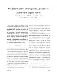
2 1. Introduction Camless valvetrains have potential advantages with respect to conventional mechanical camshafts, commanding the opening and closing phases of the intake and exhaust valves. In fact, in principle these new devices allow for optimizing every engine operating conditions. Their main advantages are fuel saving, increase of maximum and low speed torque, flattening of the toque characteristic and driveability improvement, pollution and energy consumption reduction, increase of the burn rate, possible variability of the compression rate, combustion stability improvement at low speed [11], [3], [18], [16], [1]. Nonetheless, the control of these devices represents a difficult task, and is currently an open problem. The main problems arise from the stringent specifications and from the lack of state measurement. In fact, the control specifications require that impact velocities between the valve and the constraints be sufficiently low to eliminate acoustic noises and avoid damages of the mechanical components. These problems are complicated by the short time available at high engine speed to make a transition between the two valve’s terminal positions. Moreover, in order to minimize the actuator cost and space occupancy, valve position and velocity sensors should not be considered. Some previous works on the subject are given in [4], [19], [20], [21], [13], [12], [17], [14], [15]. More recently, in [2], a state feedback controller has been proposed. It has been designed on the basis of the regulation theory and using a Lyapunov function. Generalizing that approach to the case of output feedback, the soft–landing problem is here solved with an output feedback. The problem is first translated into a regulation problem for the lift valve profile, by imposing that the valve position tracks a desired reference, while the modeled disturbances are rejected. Both reference and disturbance are generated by an autonomous system, usually called exosystem. The submanifold characterized by the zeroing of the tracking error and the rejection of the disturbance, is then determined. Finally, the stabilization problem of the system trajectory is solved using a Lyapunov function to design the state feedback. 2. Mathematical Model of the Electromagnetic Valves In this section we present the mathematical model of an ElectroMagnetic Valve System (EMVS), represented in Figure 1. This valve is composed of an anchor moving between two electromagnets. Thanks to the attractive forces applied by the electromagnets on the anchor rigidly connected with the stem of the valve, this latter can be opened or closed. In what follows we first present the dynamics of the electromagnets, then the mechanical dynamics. 2.1. Flux and Eddy Current Dynamics We first consider the equation describing the dynamics of the electric windings of the electromagnetic valve, which are [12], [17] 1 m = 1, 2 φ˙ m = (Vm − Rm Im ), (1) N where φm are the magnetic fluxes, Rm is the electrical resistances, and N is the number of turns of the windings, which is the same for both windings for each magnet. Moreover, Vm , Im are the voltages and currents of the electric circuits.
3 The currents Im can be given as a function of φm by expressing the magnetomotive force ˆ m as the sum of two terms [17] M ˆ m (ξm , φm ) = Nm (φm ) + R ˆ m (ξm )φm , M m = 1, 2 (2) with Nm (φm ) a nonlinear function of the flux φm , describing the nonlinear effects in the iron, ˆ m (ξm ) takes into account the air–gap portion, with ξm the while the magnetic reluctance R air–gap thickness. In what follows, we assume that the forces closing the valve are positive. It is worth noting that we suppose that on the anchor no magnetic material (permanent magnets) is present; therefore, each electromagnet can only attract the anchor. In the following, we will suppose that only one electromagnet is active at each time instant, with the purpose of minimizing the control effort. The functions Nm (φm ), m = 1, 2, can be described by some exponential functions obtained by a best fit procedure from experimental data Nm (φm ) = Nm0 enm φm ,
m = 1, 2.
ˆ m (ξm ) is a nonlinear function of ξm . We assume that the anchor The magnetic reluctance R is connected with the valve stem tip, and that the arc can be approximated by the cord. If xa , xv ∈ [−ρ, ρ] are the anchor tip and the valve tip positions (ρ is the maximal displacement with respect the intermediate position), with xv = xa , hence ξm can be expressed as functions of the ³ ´ ξm = ρ + (−1)m xv rl,m , m = 1, 2 (3) where 2ρ is the anchor tip displacement (coinciding with the valve vertical stroke), 0 < rl,m = dm /d < 1, m = 1, 2, are the lever ratios, and xv is positive in the same direction of xv , see Figure 1. Experimentally, one obtains the following expressions ˆ m (ξm ) = pm1 (1 − e−pm2 ξm ) + pm3 ξm , R m = 1, 2 where pm1 , pm2 , pm3 are parameters obtained by identification. It is worth noting that ˆ m (ξm ) ≥ 0 for all ξm . R Denoting by Ip,m the eddy currents in parasitic circuits with resistance Rp,m and inductance Lp,m coupled with the magnetic circuits, having dynamics [12] −Rp,m Ip,m = φ˙ m + Lp,m I˙p,m , m = 1, 2 (4) one obtains the expression of the magnetomotive forces [12] ˆ m (ξm , φm ) = Nm (φm ) + R ˆ m (ξm )φm N Im + Ip,m = M
(5)
m = 1, 2, where (2) has been used. Therefore, by substituting (5) into (1), one gets the flux dynamics ´ 1 Rm ³ φ˙ m = Vm − Mm (xv , φm ) − Ip,m , m = 1, 2 (6) N N2 where using (3) Mm (xv , φm ) = Nm (φm ) + Rm (xv )φm , m = 1, 2 ¯ ˆ m (ξm )¯¯ = − am e−bm xv + cm xv + dm Rm (xv ) = R ξm bm −pm2 rl,m ρ am = bm pm1 e , bm = (−1)m rl,m pm2 cm = (−1)m rl,m pm3 ,
dm = pm1 + rl,m pm3 .
4 Moreover, using (4), (6), one works out the eddy current dynamics, for m = 1, 2 µ ¶ 1 Rm I˙p,m = − Rp,m + Ip,m Lp,m N2 +
Rm Lp,m N 2
Mm (xv , φm ) −
1 Lp,m N
(7)
Vm .
2.2. Mechanical Dynamics The mechanical dynamics of the actuator can be obtained by writing the balance of the forces acting on the anchor, of mass Ma , and on the valve, of mass Mv . In order to consider a specific situation, as anticipated, we suppose that the anchor remains always connected with the valve during its stroke. Moreover, the contribution due to the gravity is supposed to be negligible, and all the mechanical parts of the valve are considered rigid bodies. Anchor dynamics. One first considers the (attractive) forces developed by the electromagnets on the moving anchor. Choosing the magnetic axis as reference, these magnetic forces can be written as ˆ m (ξm ) 1 dR Fˆm (ξm , φm ) = −(−1)m φ2m , m = 1, 2 2 dξm with φm the flux and ξm the air–gap thickness. Here we considered positive the force Fˆ1 , closing the valve, and negative Fˆ2 , opening the valve (see Figure 1). In order to write all the mechanical equations in the same reference, these forces can be replaced by the forces Fm , m = 1, 2, acting on the anchor’s tip, i.e. along the valve stem axis (see Figure 1), made equivalent to the forces Fˆm by equating the generated momenta ¯ 1 ¯ Fm = rl,m Fˆm (ξm , φm )¯ = − R0m (xv )φ2m , m = 1, 2 (8) ξm 2 where (3) has been considered, with R0m (xv ) =
dRm (xv ) dxv
= am e−bm xv + cm ,
m = 1, 2.
Clearly R01 (xv ) < 0 and R02 (xv ) > 0, so that F1 > 0 (closing the valve) and F2 < 0 (opening the valve), accordingly to the convention on the force signs. Obviously, both electromagnets may be supplied at the same time but, for the sake of the simplicity and without loss of generality, we assume to supply only one electromagnet at each time instant. A torsional spring keeps the anchor in an intermediate position. This force can be rendered equivalent (by equating the momenta) to a force Fel,a = −ka (xv − x◦v ) acting on the tip of the anchor, with x◦v the intermediate position, and ka the elastic coefficient for the torsion bar. Hence, considering the (equivalent) spring elastic force Fel,a (acting on the anchor’s tip), the viscous friction force Ff r,a = −ba x˙ v , the net magnetic force F = F1 + F2 , and the constraint force Fc,a due to the electromagnet surface, each considered with its sign, the anchor motion equation is given by Ma x ¨v = Fel,a + Ff r,a + F + Fc,a (9) = −ka (xv − x◦v ) − ba x˙ v + F + Fc,a
5 where ba is the viscous friction for the anchor. Note that Fc,a is always zero except for xv = ±ρ. Valve dynamics. The valve has two springs, one closing it and another opening it, which can be modeled equivalently by a single linear spring, preloaded to keep the valve in the center of its stroke x◦v when the two electromagnets are not supplied, so that the elastic force Fel,v , due to the (equivalent) valve spring is Fel,v = −kv (xv − x◦v ), with kv the elastic coefficient of the (equivalent) linear spring. Considering the other forces acting on the valve of mass Mv , namely the viscous friction Ff r,v = −bv x˙ v , the disturbance force Fd due to the exhaust gases exiting the cylinder, and the force Fc,v due to constraint given by the valve seat, the valve dynamics are Mv x ¨v = Fel,v + Ff r,v + Fd + Fc,v (10) = −kv (xv − x◦v ) − bv x˙ v + Fd + Fc,v with bv the viscous friction for the valve. The force Fd is a disturbance acting on the valve. It depends on the cam angle ϑc and parameters, such as the valve equivalent area, the load, the gas turbulence, etc. A typical behavior of Fd is given in Figure 3 as function of ϑc , along with a valve lift reference. The model of Fd in a specific case will be given in the following sections. Note that Fc,v is always zero except for xv = ρ. Mechanical dynamics. By combining (9), (10) one gets the mechanical dynamics Mx ¨v = −kxv − bx˙ v + F + Fd + Fc ´ 1³ F = − R01 (xv )φ21 + R02 (xv )φ22 2
(11)
where (8) has been considered, with M = Ma + Mv , b = ba + bv , k = ka + kv , Fc = Fc,a + Fc,v . Here we have set the center of the valve stroke x◦v as the origin for xv . Equation (11) holds for xv ∈ [−ρ, ρ]. It is worth noting that Fc is always zero except for xv = ±ρ, in which ´ 1³ 0 Fc (xv ) = kxv + R1 (xv )φ21 + R02 (xv )φ22 − Fd , xv = ±ρ. 2 2.3. Output of the System The measured variables are typically the winding currents Im and the fluxes φm . It is worth noting that while the winding currents are measured via shunt resistors, some problems could arise for the measurements of the fluxes. In fact those could be directly measured using Hall sensors inserted into the magnetic circuit. However, this solution is expensive and difficult to realize industrially due to hostile working conditions. Alternatively, the indirect measurements of the fluxes could be obtain by integrating (1). In this case the voltages are known since they are imposed by the controller, while the currents are measured. Clearly one needs to know the winding resistances Rm and the number of turns N . Unfortunately, this method suffers from resistance and power stage parameter variations. In fact, the coil resistance varies with the temperature, so we could have an unknown bias. In order to avoid these problems, the fluxes φm are determined using sensors constituted by coils, coaxial with the power coils (see Figure 1), for which Vs,m φ˙ m = , m = 1, 2 Ns
6 where Vs,m is the measured voltage and Ns is the number of sensor windings, so that Z t 1 φm = φm (t0 ) + Vs,m (τ ) dτ, m = 1, 2 N s t0 with φm (t0 ) integration offsets. The integrator circuits are reset at time t0 in order to avoid some possible offset accumulation.
3. Hybrid Model of the System and Problem Formulation In this section we present the hybrid model of the EMVS. We have seen that the attractive forces applied by the electromagnets move the valve. In order to reduce the control effort and for the sake of simplicity (but without loss of generality) we will suppose that only one electromagnet is supplied at each time instant. This means that only one flux dynamic equation is forced by the (nonzero) input, while the other is in free evolution. The system is hence described by an hybrid system Hs composed of four states qs ∈ Qs = {qs,1 , qs,2 , qs,3 , qs,4 } (see Figure 2): one for the closing phase, one when the valve is completely close, one for the opening phase, and finally one when the valve is completely open. The transitions among these models ¡ ¢T depend on the value of the system state x = xv vv φm Ip,m , so that the resulting system dynamics are x˙ =
fis (x, w, u)
(12)
e
his (x, w)
(13)
=
for is ∈ Is = {1, 2, 3, 4}, with his = xv − xr . When is = 1, 3 fis ,1 = vv fis ,2 = fis ,3 =
1 ³ M Rm
´ − kxv − bvv + F + Fd + Fc à Ip,m − Mm (xv , φm ) +
N2
fis ,4 = −
1 Lp,m +
µ ¶ Rm Rp,m + Ip,m N2 Rm
Lp,m N
2
Mm (xv , φm ) −
N Rm
! um
1 Lp,m N
um .
For the sake of clarity (see the appendix for the list of symbols), we repeat that xv ∈ [−ρ, ρ], vv are the valve position and velocity (ρ is the maximal displacement with respect the intermediate position x◦v = 0), φm is the flux of the electromagnet, Ip,m is the eddy current in the parasitic circuit, um = Vm is the voltage (control input) applied to the electromagnet, and m = 1, 2 is the supplied electromagnet. Moreover, M is the moving mass, b, k are the viscous friction and elastic coefficients, Rm is the resistance of the electromagnet circuit, N the number of turns
7 of the electromagnet windings, Rp,m , Lp,m are the resistance and inductance of the parasitic circuit. Finally, F is the (attractive) magnetic force given by (11) ´ 1³ F = − R01 (xv )φ21 + R02 (xv )φ22 2 Fd is the disturbance force (due to the exhaust gases exiting the cylinder), Fc is the constraint force (due to the valve seat and the electromagnet surfaces) given in Table 1, with 1 1 Fc,2 = kρ + R01 (ρ)φ21 − Fd , Fc,4 = −kρ + R02 (−ρ)φ22 − Fd 2 2 Mm is the magnetomotive force, which can be written as a sum Mm (xv , φm ) = Nm (φm ) + Rm (xv )φm of a nonlinear term Nm (φm ) = Nm0 enm φm (Nm0 , nm obtained experimentally) and a linear one, with Rm (xv ) = −am e−bm xv /bm + cm xv + dm the magnetic reluctance (am , bm , cm , dm experimental parameters). When is = 2, 4, fis ,1 ≡ 0, fis ,2 ≡ 0, while fis ,3 , fis ,4 are the same (with xv = ±ρ). q1
q2
q3
q4
m=1
m=1
m=2
m=2
u 1 = V1
u1 = V1
u1 = 0
u1 = 0
u2 = 0
u2 = 0
u2 = V2
u2 = V2
Fc = 0
by
Fc = Fc,2 Fc = 0 Table 1
Fc = Fc,4
The transitions among these four models are forced when the invariant conditions, given ¯ Is,1 : x ¯ xv ∈ (−ρ, ρ), F ≥ 0, for qs,1 ¯ Is,2 : x ¯ xv ≡ ρ, F ≥ 0, for qs,2 ¯ Is,3 : x ¯ xv ∈ (−ρ, ρ), F < 0, for qs,3 ¯ Is,4 : x ¯ xv ≡ −ρ, F ≤ 0, for qs,4
are violated [10]. Moreover, the transitions leaving a state qs ∈ Qs are regulated by the so– called guard conditions, namely rules stating when a certain transition can take place. Referring to Figure 2, the guard conditions are Gs,ik : x satisfies Is,k ,
j, k = 1, 2, 3, 4.
Finally, after a transition x can possibly undergo a reset of (some of) its components. In the case under study the reset functions Rjk are the identities. It is easy to incorporate in this model also valve bounces due to collisions of the valve in its seat or of the anchor with the electromagnets. The control problem is to determine a controller such that the valve is opened and closed following a desired valve lift reference trajectory (see Figure 3), while the disturbance due to
8 Fd is rejected. It is possible to translate the control problem into a regulation problem for the valve stem, imposing that the valve position xv tracks a desired reference xr , while the disturbance due to Fd is rejected. At the same time, it is important to ensure the so–called soft landing of the valve in the valve seat and on the electromagnet surfaces. Typical values of the valve velocity approaching the mechanical constraints (seating velocity) is 0.05 – 0.1 m/s.
4. The Regulation Problem for Hybrid Systems A regulation problem can be formulated for the electromagnetic valve under study, as explained in [2]. Resuming here the salient aspects, we recall that the reference and perturbation signals are generated by autonomous nonlinear dynamics w˙ = sie (w), ie ∈ Ie = {1, · · · , Ne }, assumed Poisson stable, called exosystem [5]. The reference, assumed known, is such that the soft landing of the valve in its seat and of the anchor on the surfaces of the electromagnets are ensured. A reference of this type is that depicted in Figure 3, which is composed of four parts, given by xr,1 (ϑc )=
7 X
cr,1i
ϑic
i=0
ϑc ∈ [ϑc0 , ϑc1 )
i!
xr,2 (ϑc )= −ρ
ϑc ∈ [ϑc1 , ϑc2 )
xr,3 (ϑc )= −xr,1 (ϑc − ϑc2 )
ϑc ∈ [ϑc2 , ϑc3 )
xr,4 (ϑc )= ρ
ϑc ∈ [ϑc3 , ϑc0 + 2π)
(ϑc = ω0 t is the cam’s angle, and ω0 is the crankshaft’s nominal angular velocity). 2 The coefficients in cr,1i , i = 0, 1, · · · , 7, are determined imposing some regularity conditions (so that the reference is a C 4 function – this will imply the continuity of the applied input). More precisely, at ϑc = ϑc0 = 0 the closed valve starts to open with velocity, acceleration and jerk (namely up to the third derivative) equal to zero, and is closed (with zero velocity, acceleration and jerk) at ϑc = ϑc1 (8 conditions)
xr,1 (ϑc0 ) = ρ =
7 X
cr,1i
i=0
ϑic0 i!
,
X dk xr,1 ¯¯ ϑi−k =0= cr,1i c0 , ¯ dϑkc ϑc0 (i − k)! i=k 7
xr,1 (ϑc1 ) = −ρ =
7 X
cr,1i
ϑic1
i! i=0 7 ¯ X ϑi−k dk xr,1 ¯ cr,1i c1 , =0= ¯ dϑkc ϑc1 (i − k)! i=k
k = 1, 2, 3.
9 Hence, one obtains cr1,0 cr1,1 cr1,2 cr1,3 cr1,4 cr1,5 cr1,6 cr1,7
µ ¶ ϑ40 ϑ50 ϑ60 ϑ70 = ρ −1 + 70 + 168 + 140 + 40 ∆4 ∆5 ∆6 ∆7 µ ¶ 280 ϑ30 ϑ0 ϑ2 ϑ3 =− ρ 1+3 +3 0 + 0 ∆ ∆3 ∆ ∆2 ∆3 µ ¶ ϑ0 ϑ2 ϑ3 840 ϑ20 ρ 1+4 +5 0 +2 0 = ∆2 ∆2 ∆ ∆2 ∆3 µ ¶ 1 680 ϑ0 ϑ0 ϑ2 ϑ3 ρ 1+6 =− + 10 0 + 5 0 ∆3 ∆ ∆ ∆2 ∆3 µ ¶ 1 680 ϑ0 ϑ20 ϑ30 = ρ 1 + 12 + 30 + 20 ∆4 ∆ ∆2 ∆3 µ ¶ 20 160 ϑ0 ϑ2 =− ρ 1+5 +5 0 ∆5 ∆ ∆2 µ ¶ 100 800 ϑ0 = ρ 1+2 ∆6 ∆ 201 600 ρ =− ∆7
with ∆ = ϑc1 − ϑc0 . The reference can be generated by the linear system w˙ r = sr (wr ) with
w0 . . wr = . , w7
0 0
1 0 ω0 0 1 sr (wr ) = 2 .. .. . . 0 0
···
0 0
··· .. .
0 0 0 0 wr .. .. . .
···
1 0
···
(14)
and xr,j (w) =
7 X
cr,ji wi ,
j = 1, · · · , 4.
(15)
i=0
The hybrid system Hr generating the references is depicted conditions are ¯ Ir,1 : ϑc ¯ ϑc ∈ [ϑc0 , ϑc1 ) ¯ Ir,2 : ϑc ¯ ϑc ∈ [ϑc1 , ϑc2 ) ¯ Ir,3 : ϑc ¯ ϑc ∈ [ϑc2 , ϑc3 ) ¯ Ir,4 : ϑc ¯ ϑc ∈ [ϑc3 , ϑc0 + 2π)
in Figure 4, where the invariant for qr,1 for qr,2 for qr,3 for qr,4
10 qr ∈ Qr = {qr,1 , qr,2 , qr,3 , qr,4 }, with guard and reset conditions Gr,12 : ϑc ≥ ϑc1 ,
Gr,23 : ϑc ≥ ϑc2 ,
Gr,34 : ϑc ≥ ϑc3
Gr,41 : ϑc ≥ ϑc0 + 2π Rr,12 , Rr,23 , Rr,34 , Rr,41 : w0 = 1, w1 = · · · = w7 = 0. As disturbance we consider the gas pressure Fd during the combustion phase in the cylinder. This disturbance is assumed unknown and generated by the linear system w˙ d = sd (wd ), with µ ¶ µ ¶ w8 ω0 0 0 (16) wd = , sd (wd ) = wd w9 2 1 0 and Fd,h (w) = Fd0 w8 + cd,h ( cd,h =
pa w8 1 + (w9 − pc )2 /pb
,
h = 1, 2
(17)
0 if ϑc ∈ [ϑc4 + ∆d − 2π, ϑc4 ) 1 if ϑc ∈ [ϑc4 , ϑc4 + ∆d ).
The hybrid system Hd generating the disturbance is depicted in Figure 5, where the invariant conditions are ¯ Id,1 : ϑc ¯ ϑc ∈ [ϑc4 + ∆d − 2π, ϑc4 ) for qd,1 ¯ Id,2 : ϑc ¯ ϑc ∈ [ϑc4 , ϑc4 + ∆d ) for qd,2 qd ∈ Qd = {qd,1 , qd,2 }, while the guard and reset conditions are Gd,12 : ϑc ≥ ϑc4 ,
Gd,21 : ϑc ≥ ϑc4 + ∆d
Rd,12 : w8 = 1, w9 = 0,
Rd,21 : Id
with Id the identity map. The exosystem is finally given by systems (14), (16) µ ¶ µ ¶ wr sr (wr ) w˙ = s(w), w= , s(w) = wd sd (wd ) with outputs (15), (17) switching where the invariant conditions are ¯ Ie,1 : ϑc ¯ ¯ Ie,2 : ϑc ¯ ¯ Ie,3 : ϑc ¯ ¯ Ie,4 : ϑc ¯ ¯ Ie,5 : ϑc ¯ ¯ Ie,6 : ϑc ¯
(18)
according to the hybrid system He depicted in Figure 6, ϑc ∈ [ϑc0 , ϑc1 )
for qe,1
ϑc ∈ [ϑc1 , ϑc4 )
for qe,2
ϑc ∈ [ϑc4 , ϑc2 )
for qe,3
ϑc ∈ [ϑc2 , ϑc4 + ∆d )
for qe,4
ϑc ∈ [ϑc4 + ∆d , ϑc3 )
for qe,5
ϑc ∈ [ϑc3 , ϑc0 + 2π)
for qe,6
11 while the guard and reset conditions are Ge,12 : ϑc ≥ ϑc1 ,
Ge23 : ϑc ≥ ϑc4 ,
Ge,45 : ϑc ≥ ϑc4 + ∆d ,
Ge34 : ϑc ≥ ϑc2
Ge56 : ϑc ≥ ϑc3
Ge,61 : ϑc ≥ ϑc0 + 2π µ ¶ Rr,12 (wr ) Re,12 (w) = , wd µ ¶ Rr,23 (wr ) Re,34 (w) = , wd µ ¶ Rr,34 (wr ) Re,56 (w) = , wd
µ
¶ wr Re,23 (w) = Rd,12 (wd ) µ ¶ wr Re,45 (w) = wd µ ¶ Rr,41 (wr ) Re,61 (w) = . wd
Note that ie ∈ {1, · · · , 6} remains associated to a certain pair (j, h), j = 1, · · · , 4, h = 1, 2. Finally, from Hs , He it is possible to determine the hybrid system H describing the dynamics of the EMVS plus the exosystem. It can be determined for instance as the shuffle product of Hs , He [?]. The generic discrete state of H is q = qi ∈ Q = {q1 , · · · , qN }, and to i ∈ I = {1, · · · , N } there corresponds a triple ` = (is , j, h) denoting the system describing the EMVS, the reference xr,j to follow, and the disturbance Fd,h to reject. Let T` the time interval during which H is in qi ∈ Q. One can introduce the so–called time basis for H [10], as the sequence of such time intervals T` . In order to solve the control problem, one needs first to solve the so–called regulator equations. Let H be in q = qi , and let ` = (is , j, h) be the corresponding triple. When is = 1 or is = 3, they are Ls πxv = πvv Ls πvv = Ls πφm =
1 ³ M Rm N
Ls πIp,m = −
2
´ − kπxv − bπvv + πF + Fd,h
πIp,m − 1
Lp,m +
Rm N
Ã
2
Mm (πxv , πφm ) +
Rp,m + Rm
Lp,m N
2
Rm
!
N2
1 N
cm (19)
πIp,m
Mm (πxv , πφm ) −
0 = πxv − xr,j where L stands for the classical Lie derivative [5], and 1 πF = − R0m (πxv )πφ2 m . 2
1 Lp,m N
cm
12 Here xr = xr,1 , Fd = Fd,1 if the system is in q = qs,1 , and xr = xr,3 , Fd = Fd,2 if the system is in q = qs,3 . As shown in [2], the solution is ½√ α if α ≥ 0 πxv = xr,j (w), πvv = Ls πxv , πφm = 0 otherwise α = −2
Fd,h − βj R0m (πxv )
βj = kπxv + bLs πxv + M L2s πxv
,
(α = αis ,j,h ). Note that if qs = qs,1 , R0m = R01 < 0, while R0m = R02 > 0 if qs = qs,3 (namely, note that πφ depends on the state qs of the system, and not only on the state qe of the exosystem). Moreover, πIp,m is solution of the fourth of (19), which admits solution because the corresponding differential equations (4) have eigenvalues −Rp,m /Lp,m with negative real parts. The analytic expression of πIp,m can not be given. Furthermore, πIp,m can not be given in a numeric form because the initial conditions are unknown. Therefore, one can consider the following observers for πIp,1 , πIp,2 Ls π ˆIp,m = − where π ˆIp,m (0) is known and where ½√ α ˆ π ˆ φm = 0
Rp,m Lp,m
π ˆIp,m −
if α ˆ≥0 otherwise
1 Lp,m
Ls π ˆ φm
α ˆ = −2
(20)
Fˆd,h − βj R0m (πxv )
is an estimate of πφm . It will be shown that the error dynamics of eIp,m = πIp,m − π ˆIp,m are exponentially stable, i.e. π ˆIp,m tend exponentially to πIp,m . Finally, from the third equation of (19) R R cm = N Ls πφm − π ˆIp,m + Mm (πxv , πφm ). N N If is = 2 (x = ρ) or is = 4 (x = −ρ), the regulator equations are Ls π x v = 0 Ls πvv = 0 Ls π φ m = Ls πIp,m
Rm ³ N2
πIp,m − Mm (±ρ, πφm ) +
N Rm
´ cm
µ ¶ 1 Rm Rp,m + πIp,m =− Lp,m N2 +
Rm Lp,m N
2
Mm (±ρ, πφm ) −
(21)
1 Lp,m N
cm
0 = ±ρ − xr (the last equation is identically verified) and the solutions are πxv = ±ρ, πvv = 0, while πφm , cm have the same form. For πIp,m one considers the estimate π ˆIp,m converging to πIp,m .
13 5. State Feedback Regulation Suppose that H is in qi ∈ Q for a certain time interval T` . We have already noted that i ∈ I corresponds to a triple ` = (is , j, h). In this section we will determine a control law ensuring that the reference is followed, rejecting the disturbance. This control will need the knowledge of the whole state. Let us first consider the following Lyapunov function candidate µ ¶ xv − πxv 1 2 V`,1 = kzm kPs , zm = , Ps = PsT > 0 vv − πvv 2 2
T where kzm kPs = zm Ps zm . Considering the mechanical subsystem (first two equations of the EMVS model), and the equations µ ¶ µ ¶ Ls πxv πxv =A + B(πFm + Fd ). Ls πvv πv v
with
Ã
the derivative of V`,1
! Ã ! 0 1 0 A= , B= 1 −k − b M M M along the trajectories of this subsystem is 2 V˙ `,1 = − kzm kQs + B T Ps zm (Fm − πFm )
with Ps solution of (Ps A + AT Ps )/2 = −Qs , Qs = QTs > 0. Since R0m (xv ) 6= 0, ∀ xv , we can write ³ ´ 1 Fm − πFm = − R0m (xv ) φ2m − κ2s πφ2 m 2 p with κs (xv , w) = R0m (πxv )/R0m (xv ). Therefore, let us consider the subsystem given by the mechanical plus the flux dynamics (first three equations of the EMVS model) and the following Lyapunov function candidate V` = V`,1 + If the control law is u = κs cm +
" Rm 1 N
2
N2 2R
zφ2 ,
zφ = φm − κs πφm .
¡ ¢ R0m (xv ) φm + κs πφm B T Ps zm − k3 zφ #
− zI + Mm (xv , φm ) − κs Mm (xv , πφm ) + κ˙ s πφm ¡ ¢ b κ˙ s = − j κs vv − πvv , j = 1, 2, zI = Ip,m − κs π ˆIp,m tends ˆIp,m , k3 > 0, where we recall that π 2 exponentially to πIp,m , one finally obtains ° ° ° z m °2 2 2 ˙ ° ° . V` = − kzm kQs − k3 zφ ≤ −λs ° zφ °
(22)
14 This shows that xv , vv , φm exponentially tend to πxv , πvv , πφm , since κs tends to 1. Finally, the easiest way to check that Ip,m exponentially tends to πIp,m is to consider that, from equations (7) one gets ´ ´ 1 ³˙ Rp,m ³ Ip,m − πIp,m − φm − Ls πφm I˙p,m − Ls πIp,m = − Lp,m Lp,m which are exponentially stable dynamics forced by a term going to zero (ISS stability). The stability of the whole switching system (12), (13) can be stated on the basis of the assumption of existence of the so called dwell time [9]. In fact, let τd,i be the dwell time of the `th system in the state q` , with τd = min τd,` . Moreover, for the `th ∈ I system we have `
determined a Lyapunov function V` such that ° ° ° °2 ° zm °2 ° ° ° ≤ V` ≤ k2,` ° zm ° , k1,` ° ° zφ ° ° zφ °
° ° ° zm °2 ° V˙ ` ≤ −k3,` ° ° zφ °
for appropriate values k1,` , k2,` . Note that k3,` can be fixed arbitrarily large. Therefore, k V˙ ` ≤ − 3,` V` , so that k2,` k3,` − τd V` (t`+1 ) ≤ V` (t` + τd ) ≤ e k2,` V` (t` ) t`+1 = t0` . When in the state q`+1 V`+1 (t`+1 ) ≤ k` =
k2,`+1 k1,`
V` (t`+1 ) ≤ k` e−λ` τd V` (t` ).
k2,`+1 k , λ` = 3,` . If H is again in q` after ν switches, it is easy to check that k1,` k2,` Vs,`+ν (t`+ν ) ≤ k` k`+1 · · · k`+ν−1 e
−
`−1 P
λ`+h τd
h=0
V` (t` ).
It is now sufficient to show that for every pair of time intervals T` , T`+ν , in which the switching system is in q` , one has V` (t`+ν ) − V` (t` ) ≤ −W` (t` ) for a (family) of positive definite continuous functions W` , ` ∈ I. For instance, if one considers ° ° ° zm °2 ° ° , for an arbitrarily small ² > 0, the stability of the switching system is W` (t` ) = ²k1,` ° zφ ° ensured taking λ` = · · · = λs,`+ν−1 = λ and λ>
1 τ d ∆`
³ ´ ln k` k`+1 · · · k`+ν−1 ,
∆` =
`−1 X
1
h=0
k2,`+h
.
6. Simulation Results The control low has been implemented on a digital computer to test the performance. A seating velocity of 0.05 m/s, a transition time of 3 ms, maximal current of 30 A, and a maximal
15 dissipated power of 1 kW have been considered. In the following we give the values of the system’s parameters. k= 117000 N/m M = 0.1054 Kg
b = 6 Ns/m N = 50
Lp,1 = 4.8000 × 10⁻⁶ Rp,1 = 0.0451 Ω R1 = 0.2040 Ω rl,1 = 0.57813
Lp,2 Rp,2 R2 rl,2
= 8.0745 × 10⁻⁶ H = 0.0234 Ω = 0.2440 Ω = 0.452
nm = 8.64 × 10³
H0j = 31.66 am = bm pm1 e−pm2 rl,m ρ cm = (−1)m rl,m pm3 ρ= 0.004 m
bm = (−1)m rl,m pm2 dm = pm1 + rl,m pm3
m = 1, 2, and (in Nm/Wb2 ) p11 = 1.5167 × 10⁶
p21 = 1.5330 × 10⁶
p12 = 1.1473 × 10³
p22 = 996.5755
8
p13 = 3.8869 × 10
p23 = 1.8226 × 10⁸ .
The following figures summarize the simulation results. The tracking error is of the order 10−6 m. Moreover, the maximal seating velocity results to be 0.0018 m/s. This implies the respect of the control requests.
Conclusions In this paper a controller has been designed for a camless engine, in which the main control problem is represented by the so–called soft landing. The approach follows the regulation theory. The main limitation of the derived controller is the use of the whole state. In fact, a technological request is the elimination of the valve position sensor. Nevertheless, works are in progress to extend the present controller to a dynamic one, using only output measurements.
References 1. M. S. Ashhab, A. G. Stefanopoulou, J. A. Cook, and M. Levin, Camless Engine Control for Robust Unthrottled Operation, Society of Automotive Engineers, Paper 960 581, 1996. 2. S. Di Gennaro, B. Castillo Toledo, and M. D. Di Benedetto, Nonlinear Regulation of Electromagnetic Valves for Camless Engines, Proceedings of the 45th IEEE Conference on Decision and Control, San Diego, CA, USA, to appear , December 13–15, 2006. 3. C. Gray, A Review of Variable Engine Valve Timing, Society of Automotive Engineers, Paper 880 386, 1988. 4. W. Hoffmann, K. Peterson, and A. G. Stefanopoulou, Iterative Learning Control for Soft Landing of Electromechanical Valve Actuator in Camless Engines, IEEE Transactions on Control Systems Technology, Vol. 11, pp. 174–184, March 2003. 5. A. Isidori, Nonlinear Control Systems, Third Edition, Springer Verlag, Berlin, Germany, 1995.
16 6. J. E. Hopcroft and J. D. Ullman, Introduction to Automata Theory, Languages and Computation, Addison–Wesley, 1979. 7. J. Huang, Nonlinear Output Regulation: Theory and Applications, SIAM, Philadelphia, Pennsylvania, USA, 1995. 8. H. K. Khalil, Nonlinear Systems, Third Edition, Prentice Hall, Upper Saddle River, New Jersey, USA, 2002. 9. D. Liberzon, Switching in Systems and Control, Birkh¨ auser, Boston, USA, 2003. 10. J. Lygeros, C. Tomlin, S. Sastry, Controllers for reachability specifications for hybrid systems, Automatica, Special Issue on Hybrid Systems, Vol. 35, pp. 349–370, March, 1999. 11. M. Monatnari, F. Ronchi, C. Rossi and A. Tonielli, Control of a Camless Engine Electromechanical Actuator: Position Reconstruction and Dynamic Performance Analysis, IEEE Transactions on Industrial Electronics, Vol. 51, No. 2, pp. 299–311, April 2004. 12. M. Marchi, A. Palazzi and M. Panciroli, Innovative Valve Control (IVC) Model, Variable Ventilsteuerung: Ein Verfahren zur Reduzierung von Kraftstoffverbrauch und Emissionen, Stefan Pischinger Ed., Expert Verlag, Renningen, pp. 114–129, Expert Verlag, Renningen, 2002. 13. K. Peterson, A. Stefanopoulou, Y. Wang, M. Haghgooie, Nonlinear Self–Tuning Control for Soft Landing of an Electromechanical Valve Actuator, Proceedings of 2002 IFAC on Mechatronics, 2002. 14. K.Peterson, A. Stefanopoulou, T. Megli, M. Haghgooie, Output Observer Based Feedback for Soft Landing of Electromechanical Camless Valvetrain Actuator, Proceedings of the 2002 American Control Conference, Vol. 2, pp. 1413–1418, 2002. 15. K. Peterson, A. Stefanopoulou, Y. Wang, Control of Electromechanical Actuators: Valves Tapping in Rhythm, Kathy Peterson, Yan Wang, Anna Stefanopoulou, in Multidisciplinary Research in Control: The Mohammed Dahleh Symposium 2002, Eds. L. Giarr` e and B. Bamieh, Lecture Notes in Control and Information Sciences, No. 289, Springer–Verlag, Berlin, 2003. 16. M. Pischinger, W. Salber, F. van der Staay, H. Baumgarten, and H. Kemper, Benefits of Electromechanical Valve Train in Vehicle Operation, Society of Automotive Engineers, Paper 2000-01-1223, 2000. 17. F. Ronchi, C. Rossi and A. Tilli, Sensing Devices for Camless Engine Electromagnetic Actuators, IEEE Conference of the Industrial Electronics Society, Vol. 2, pp. 1669–1674, 2002. 18. M. Schechter, M. B. Levin, Camless Engine, Society of Automotive Engineers, Paper 860 581, 1996. 19. C. Tai, A. Stubbs, T.-C. Tsao, Modeling and Controller Design of an Electromagnetic Engine Valve, Proceedings of the American Control Conference, Arlington, VA June 25–27, 2001. 20. Y. Wang, A, Stefanopoulou, M. Haghgooie, I. Kolmanovsky, and M. Hammoud, Modeling of an Electromechanical Valve Actuator for a Camless Engine, Proceedings of the 2001 American Control Conference, Arlington, VA June 25–27, 2001. 21. Y. Wang, T. Megli, M. Haghgoogie, K. S. Peterson and A. G. Stefanopoulou, Modeling and Control of Electromechanical Valve Actuator, Society of Automotive Engineers, 2002.
Appendix – List of Symbols H I qi q Q Gjk Rjk Hs Is qs,is qs Qs Gs,jk Rs,jk x
Hybrid system, composition of Hs and He Set of indexes of the discrete states of H, I = {1, · · · , N } Discrete state of H Generic discrete state of H, q ∈ Q Discrete state set of H Guard condition from qj to qk Reset from qj to qk Hybrid system describing the EMVS Set of indexes of the discrete states of Hs , Is = {1, · · · , Ns } Discrete state of Hs Generic discrete state of Hs , qs ∈ Qs Discrete state set of Hs Guard condition from qs,j to qs,k Reset from qs,j to qs,k Continuous state of the system x˙ = fis (x, w, u), is ∈ Is
17 u Input of the system x˙ = fis (x, w, u), is ∈ Is e Error output e = his (x, w), is ∈ Is fis Dynamics of the system x˙ = fis (x, w, u), is ∈ Is his Output of the system x˙ = fis (x, w, u), is ∈ Is Hr Reference hybrid system Hd Disturbance hybrid system He Exosystem hybrid system qe,ie Discrete state of He qe Generic discrete state of He , qe ∈ Qe Qe Discrete state set of He Ge,jk Guard condition from qe,j to qe,k Re,jk Reset from qe,j to qe,k w State of the exosystem w˙ = sie (w), ie ∈ Ie seie (w) Dynamics of the exosystem w˙ = sie (w) Ie Set of indexes of the discrete states of the exosystem He , Ie = {1, · · · , Ne } xv Valve position vv Valve velocity xa Anchor position (here xa = xv ) m Generic magnet, m = 1, 2 φm Flux of the electromagnet circuit, m = 1, 2 Im Current of the electromagnet circuit, m = 1, 2 Vm Voltage of the electromagnet circuit, m = 1, 2 Rm Electrical resistance of the electromagnet circuit, m = 1, 2 N Number of turns of the windings of the electromagnet circuit, m = 1, 2 ˆ m Magnetomotive force of the electromagnet, m = 1, 2, expressed as a function of ξm M ˆ m Magnetic reluctance, i.e. the linear term of the magnetomotive force, m = 1, 2, expressed R as a function of ξm ˆ m = pm1 (1 − e−pm2 ξm ) + pm3 ξm , m = 1, 2, ` = 1, 2, 3 pm` Parameters of R ξm Air–gap thickness for the electromagnet, m = 1, 2 Mm Magnetomotive force of the electromagnet, m = 1, 2, express as a function of xv Rm Magnetic reluctance, i.e. the linear term of the magnetomotive force, m = 1, 2, express as a function of xv Nm Nonlinear term of the magnetomotive force, m = 1, 2 Nm0 Constant term of the magnetomotive force, m = 1, 2, Nm = Nm0 enm φm nm Exponential of the magnetomotive force, m = 1, 2, Nm = Nm0 enm φm Ip,m Eddy currents in the parasitic circuit, m = 1, 2 Rp,m Resistance of the parasitic circuit, m = 1, 2 Lp,m Inductance of the parasitic circuit, m = 1, 2 Ip,m Eddy currents in parasitic circuits, m = 1, 2 rl,m Lever ratio, m = 1, 2 d Distance between the valve axis and the anchor pivot d1 Distance between the axis of the force F1 and the anchor pivot d2 Distance between the axis of the force F2 and the anchor pivot Fˆm Magnetic force (attractive) developed by the electromagnet m on the moving anchor, m = 1, 2, expressed in the magnetic axis reference as a function of ξm Fm Magnetic force (attractive) developed by the electromagnet m on the moving anchor,
18 m = 1, 2, expressed in the valve axis reference as a function of xv F Net magnetic force F = F1 + F2 Fel,a Elastic force acting on the anchor Ff r,a Viscous friction force acting on the anchor Fc,a Constraint force acting on the anchor and due to the electromagnet surface x◦v Intermediate position for the anchor and the valve (set equal to zero) Ma Anchor mass ba Viscous friction coefficient for Ff r,a ka Elastic coefficient for the torsion bar of the anchor Fel,v Elastic force acting on the valve Ff r,v Viscous friction force acting on the valve Fc,v Constraint force acting on the valve and due to the valve seat Fd Disturbance force due to the exhaust gases exiting the cylinder Fd,h Part h of the disturbance force due to the exhaust gases exiting the cylinder Mv Valve mass bv Viscous friction coefficient for Ff r,v kv Elastic coefficient for the (equivalent) linear spring of the valve ϑ Crankshaft’s angle, ϑ ∈ [0, 4π) ω Crankshaft’s angular velocity ω0 Crankshaft’s nominal angular velocity ϑc Cam’s angle, ϑc = ϑ/2 ∈ [0, 2π) M Total mass (anchor plus valve), M = Ma + Mv b Total viscous coefficient, b = ba + bv k Total elastic coefficient, k = ka + kv Fc Total constraint force, Fc = Fc,a + Fc,v Vs,m Sensor voltage (measured) Ns Number of the sensor windings xr Reference valve position xr,j Part j of the reference valve position crj,i Generic coefficient i = 0, · · · , 7 for xr,j λQ min the minimum eigenvalue of the matrix Q λQ max the maximum eigenvalue of the matrix Q
19 xv d d1 Electromagnet 1
Coils
Vs,1
Anchor
Torsion bar
Vs,2 Coils
F1
F^1
V1 F^2
½
F2
0
Valve Stem
¡½ V2
Electromagnet 2 d2
Valve spring
Engine Head Valve
Fd
Figure 1. Scheme of a Electromagnetic Valve System
20
Gs,21
Rs,21 .
qs,1
x = f1(x,w,u) e = h1(x,w) Is,1
Rs,12
Gs,12
.
x = f2(x,w,u) e = h2(x,w) Is,2
qs,2
Gs,13 Rs,41
Gs,23 Rs,31 Rs,13
Gs,41
Rs,23 Gs,31
.
qs,4
x = f4(x,w,u) e = h4(x,w) Is,4
Rs,34
Gs,34
.
x = f3(x,w,u) e = h3(x,w) Is,3
Figure 2. Hybrid system Hs modeling the EMVS
qs,3
21
xr,j(#c) j =2
½
j =3
j =1
j =4 ¡½ #c #c0
#c1
#c2 #c3 #c0+2¼
Fd,h(#c)
h=2
Fd0
h=1 #c
#c4+¢d¡2¼
#c4 #c0
#c4+¢d #c0+2¼
Figure 3. Reference trajectory xr and disturbance Fd as functions of the cranckshaft’s angle ϑc
22
Gr,12
qr,1
Rr,12
. wr = sr(wr) xr = xr,1 Ir,1
. wr = sr(wr) xr = xr,2 Ir,2
qr,2
Rr,41
Gr,23
Gr,41
Rr,23
qr,4
. wr = sr(wr) xr = xr,4 Ir,4
Rr,34
Gr,34
. wr = sr(wr) xr = xr,3 Ir,3
qr,3
Figure 4. Reference hybrid system Hr
Gd,12
qd,1
Rd,12 . wd = sd(wd) Fd = Fd,2
. wd = sd(wd) Fd = Fd,1
Id,2
Id,1 Rd,21
Gd,21
Figure 5. Disturbance hybrid system Hd
qd,2
23
qe1 Re,23
. . w = s(w) Ge,12 Re,12 w = s(w) xr = xr,2 xr = xr,1 Fd = Fd,1 Fd = Fd,1 Ie,1 Ie,1
Ge,23 Re,23
Ge,23
qe,6
qe,2
. w = s(w) xr = xr,2 Fd = Fd,2 Ie,3
. w = s(w) xr = xr,4 Fd = Fd,1 Ie,1 Re,34
Ge,34
Ge,34 qe,5
. w = s(w) xr = xr,3 Fd = Fd,1 Ie,5
Re,12
Ge,12
. w = s(w) xr = xr,3 Fd = Fd,2 Ie,4
Figure 6. Exosystem hybrid system He
Re,34 qe,4
qe,3
24
−3
5
x 10
4
3
2
1
0
−1
−2
−3
−4
−5
0
0.02
0.04
0.06
0.08
0.1
0.12
0.14
0.16
Figure 7. Valve position xv and reference xr = πxv
0.18
0.2
25
−3
8
x 10
7
6
5
4
3
2
1
0
0
0.02
0.04
0.06
0.08
0.1
0.12
0.14
Figure 8. Tracking error of position xv − xr
0.16
0.18
0.2
26
5
4.5
4
3.5
3
2.5
2
1.5
1
0.5
0
0
0.02
0.04
0.06
0.08
0.1
0.12
0.14
Figure 9. Tracking error of velocity vv − vr
0.16
0.18
0.2