successful technology for cost effective solution because it simplifies the remote .... [10] J. H. Seo, Y. K. Seo, W. Y. Choi, âNonlinear distortion suppression in ...
Nonlinear distortion reduction in directly modulated semiconductor laser using feedforward linearisation T Ismail and A J Seeds University College London Abstract – This paper outlines an approach to optical feedforward linearisation technique to reduce nonlinear distortion generated by a directly modulated semiconductor laser diode for Wireless Local Area Network (WLAN) operating in the Industrial Scientific -Medical (ISM) band 2.4 GHz (IEEE802.11b) for Radio over Fibre (RoF). Various linearization techniques are reviewed. Results with feedforward linearis ation have shown over 10 dB reduction in Intermodulation Distortion IMD in frequency range of 2.2 GHz – 2.7 GHz. 1.
Introduction
The existing copper based telecommunication networks do not support the ni creased demand for broadband mobile services such as video-on-demand, Wireless LAN and mobile computing and this requires the need to develop high capacity mobile communication networks which are capable of delivering broadband signals to remote areas “over the air” [1]. Due to high bandwidth requirements for broadband services and congested spectrum at low frequencies this has led to research in transmission of microwave and mm wave signals using optical fibre known as Radio–over-Fibre. The principal advantages of the transmission of high frequency signals over fibre are low attenuation and cost when compared to the conventional coaxial cable and the large aggregated information capacity even when only part of the optical bandwidth is exploited. Propagation of signals at microwave and mm wave frequencies requires the radio base stations to be closely spaced in distance and use micro cellular architecture with a high degree of frequency reuse. The concept of frequency reuse is particularly beneficial in a W ireless LAN where the cells are essentially confined to small size. In order to cover a given area this requires a large number of base stations and therefore, it is desirable to have simple and low cost system. RoF concept seems to be the successful technology for cost effective solution because it simplifies the remote Antenna Unit (RAU) and allows the sharing of expensive equipment which could be located at a Central Site (CS). Direct modulation of laser diode has limited dynamic range due to intermodulation distortion products present in the laser output intensity spectrum. In this work, the use of feedforward linearization to reduce these nonlinear distortion products is demonstrated with potential applications in wireless LAN.
2.
Background
The process of modulation methods can be divided as direct and indirect modulation. Direct modulation of semiconductor lasers can be used for simple and low cost systems . In a directly modulated laser, the main source of distortion is caused by the intrinsic nonlinearities of the laser which limits the dynamic range and hence the system performance. Any non linear distortion generated by the semiconductor laser such as intermodulation distortion can also give rise to interchannel interference which degrades the quality of the received signal. These distortion products can be analyzed as follows. Considering the power series model we can see how the intermodulation products are generated in a system. Y(t) = a + b[X(t)] + c[X(t)]2 + d[X(t)]3 + …. (Higher order terms) Y is the detected electrical signal, X is the RF input signal and c, d are coefficients which specify the nature of the non-linearity If the input consists of two sinusoid signals with different frequency then third order intermodulation distortion signals are generated very close to the operating channels which are difficult to remove using filters. The magnitude of the 3rd order signals can be large and can not be ignored. These undesired output frequency components produce distortion and degrade the performance of the system and must be minimised or ideally completely removed.
Several techniques have been used to improve the linearity of semiconductor lasers using Optoelectronic Feedback technique, Predistortion and feedforward linearization. Optoelectronic feedback [2] can be used to reduce the distortion in a same way as electronic feedback but the limitations are that the loop delay must be very small and this limits the maximum frequency of operation. Predistortion is a simple linearization technique and utilizes a non linear device which generates distortion products that are equal in amplitude but opposite in phase compared to that of the transmitter. This results in the overall system that is much more linear. This technique has been widely used in linearising LEDs [3], laser transmitters for CATV [4] and radio over fibre systems for 0.4 – 2 GHz [5]. The Predistortion circuit requires the network to be matched and adjusted to the individual laser and does not reduce non linear distortion of all orders. Therefore, feedforward linearisation is preferred. Although the circuit for the feedforward compensation is more complicated and can be difficult to implement, it seems to be the most promising technique for broadband linearization and offers a number of advantages compared to other techniques such as broadband distortion reduction at microwave frequencies, reduction in all orders of distortion can be achieved, and the non linear characteristics of the lasers do not need to be known. Unlike predistortion, feedforward is able to reduce the laser relative intensity noise (RIN) [6] as well. A reduction in the intensity noise of more than 10 dB has been observed over a frequency range of 1.7 – 3 GHz [7]. Since the noise limits the dynamic range in a system, reducing the nonlinear distortion together with the RIN noise can further enhance and improve the dynamic range. Other techniques have been reported for the reduction of nonlinear distortion such as External Light Injection [8], External Optical Injection Locking [9], and Sidemode Optical Injection [10].
3.
Experimental arrangement of Feedforward Linearization
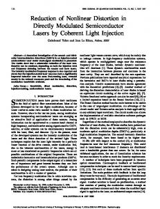
The circuit for feedforward linearization is shown in figure 1. The circuit uses two semiconductor lasers, a photodiode and microwave devices such as amplifiers, attenuators, adjustable delay line. The circuit is based on two main loops: i) The inner loop (error determination loop) ii) The outer loop (error injection loop)
F1 F2
F1 Isolator
F1 F2 2F1-F2
2F2-F1
RF Generator 1 Electrical Coupler 2 Electrical Coupler 1
F2
F1 F2 2F1-F2
Laser 1 Output
RF Generator 2 Isolator
Optical Coupler 2
Optical Coupler 1
Variable Attenuator
Path B
Photodiode
Laser 2
F1 F2 Phase shifter
2F1-F2
2F2-F1
Path A
Electrical Optical
F1 F2
Electrical Coupler 3
2F1-F2
F1 F2
2F2-F1
Delay & Attenuator
2F2-F1
Figure 1 Circuit setup for feedforward linearization 3.1. Operation RF generators are used to provide the two tone signals to the system and the two signals are combined in electrical coupler 1. Microwave isolators are used at the output of each RF generator to provide high isolation between the generators. The RF signal at the electrical coupler 2 is split into two paths A and B. Considering the inner loop first the signal at path B modulates the laser 1 (DC bias not shown) and this optical signal is detected by the photodiode. Due to nonlinearity in the laser, distortion is generated resulting in additional frequency components. The electrical signal is amplified after the photodiode to compensate for the loss in the laser path. This signal together with the signal from path A which is the error free reference signal is subtracted at the electrical coupler 3 leaving only the distortion products from the laser called the error signal. Path A is the distortion free path and consists of a variable attenuator and a microwave adjustable delay line. These components are adjusted to ensure that the delay introduced by path B is equal to the delay in path A and the two signals arrive simultaneously at coupler 3. Maximum carrier suppression will be achieved when the two signals are equal in amplitude and opposite in phase. For broadband response the two paths must also be delay matched. The error signal produced at the output of coupler 3 drives the second laser and the signal is delayed and amplified by amplifier 2. The output of laser 2 is combined with the optical signal from laser 1 at optical coupler 2 and this results in cancellation of distortion products . Again it is important to ensure that the two signals arriving at the optical coupler 2 are delay and phase matched. Perfect cancellation of the distortion can be achieved when exact matching of the signals is obtained at optical coupler 2. In theory distortion can be completely eliminated. However, in practice this does not happen due to amplitude mismatch, nonideal frequency response of components such as amplifiers and photodetectors and phase mismatch due to error in adjusting the time delay and the fibre delay in the feedforward system. Also the distortion produced by laser 2 is not compensated but this can be minimised by ensuring that the second laser is driven by a small signal. The presence of intensity noise generated by laser 2, shot noise in the photodiode and amplifier noise limits the maximum achievable improvement in dynamic range. The proportion of noise coupled to the output depends on the coupling ratio of the optical coupler 2 and this can be minimised by using a coupler which has a coupling ratio of 10 dB or more.
4.
Results
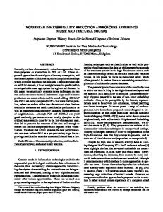
The performance of the feedforward linearization has been assessed and in figure 2 the results show approximately 20 dB suppression in IMD around 2.4 GHz with two tones spaced by 10 kHz. Further suppression of the IMD to the noise floor level can be achieved by more accurate phase and amplitude matching.
Two tones with Feedforward
Two tones without Feedforward -40
-40
-60
-60
-80
-80
-100
-100
-120
-120
-140 2.39998 10
-140 9
2.39999 10
9
2.4 10 9
2.40001 10
Frequency
9
2.40002 10
9
2.40003 10
9
2.39998 10
9
2.39999 10
9
2.4 10 9
2.40001 10
Frequency
9
2.40002 10
9
2.40003 10
9
Figure 2 Two tone results 5. Conclusion and further work In conclusion, the third order intermodulation distortion of a directly modulated semiconductor laser with and without feedforward linearization has been investigated. The experimental results show approximately 20 dB reduction in IMD around 2.4 GHz and more than 10 dB suppression over a frequency range of 2.2-2.7 GHz. The work carried out this far has been in the frequency range of 2.2 GHz to 2.7 GHz to cover the ISM band for IEEE802.11b standard. Further improvements will make the feedforward a wideband system to cover the IEEE802.11a frequency range around 5.7 GHz. The system is narrowband at the moment due to poor modulation response of the laser diode affecting the overall system performance. Ho wever, with new lasers future activities will focus on a broadband linearisation of the laser diode to cover both the IEEE802.11b and IEEE802.11a frequency bands.
References [1]
[2] [3] [4]
[5]
[6]
[7]
[8]
[9]
[10]
A. Kaszubowska, P. Anandrajah, L. P. Barry, “Optically fed microwave system using laser diodes with enhanced modulation bandwidth”, High Frequency Postgraduate Student Colloquium, IEEE, pp 59-64, Sept 2000 R. S. Tucker, “Linearization techniques for wideband analog transmitters”, LEOS 1992 Summer Topical Meeting Digest, pp 54 – 55, 29 Jul-12 Aug 1992 K. Asatani, T. Kimura, “Linearization of LED nonlinearity by predistortion”, IEEE Journal of Solid State Circuits, Vol SC-13, No 1, Feb 1978, pp 133- 138 H. Lin, Y. Kao, “Nonlinear distortions and compensations of DFB laser diode in AM-VSB lightwave CATV applications”, Journal of Lightwave Technology, Vol 14, No 11, Nov 1996, pp 2567- 2574 F. Zepparelli, L. Roselli, F. Ambrosi, R. Sorrentino, P. Faccin, A. Casini, “Modelling and design of broadband predistortion circuit for Radio-over-Fibre systems”, IEICE Trans. Electron, Vol E85-C, No3, March 2002, pp 519-526 L.S. Fock, A. Kwan, R.S. Tucker, “Reduction of semiconductor laser intensity noise by feedforward compensation: experiment and theory”, Journal of Lightwave Technology, Vol 10, No 12, pp 1919-1925, December 1992 L. S. Fock, R.S. Tucker, “Simultaneous reduction of intensity noise and distortion in semiconductor lasers by feedforward compensation”, Electron. Lett. Vol 27, No 14, pp 12971299, July 1991 M. H. Pua, M. K. Haldar, F. V. C. Mendis, H. K. Garg, “Reduction of nonlinear distortion in semiconductor lasers with external light injection”, International Conference on Information, Communications and signal Processing, pp 1153 – 1157, September 1997 X. J. Meng, T. Chau, M. C. Wu, “Suppression of intermodulation distortion in DFB lasers by external optical injection locking”, Optical Fibre Communication Conference, 1999, and the International Conference on Integrated Optics and Optical fibre Communication, OFC/IOOC 99, Technical digest, Volume 3, 21-26 Feb 1999, pp 335-337 J. H. Seo, Y. K. Seo, W. Y. Choi, “Nonlinear distortion suppression in directly modulated DFB lasers by sidemode optical injection”, IEEE MTT-S Digest, pp 555 – 558, 2001