Abstract- The differential equations of motion and their boundary conditions for a rotating beam such as a helicopter rotor blade are formulated via Hamilton's ...
0360-5450/86 $3.00 + 0.00 Copyright © 1986 Pergamon Journals Ltd
Vertica Vol. 10, No . 2, pp. 151- 169, 1986 Printed in Great Britain. All rights reserved
NONLINEAR FLEXURE AND TORSION OF ROTATING BEAMS, WITH APPLICATION TO HELICOPTER ROTOR BLADES- I. FORMULATION MARCELO R. M. CRESPO DA SILVA*' and DEWEY H . HoDGEst2 'Department of Mechanical Engineering, Aeronautical Engineering and Mechanics, Rensselaer Polytechnic Institute, Troy, NY 12181 , U.S.A. Aerofiightdynamics Directorate, U.S. Army Aviation Research and Technology Activity (AVSCOM), Ames Research Center, Moffett Field, CA 94035, U.S.A.
2
(Received December 1984)
Abstract- The differential equations of motion and their boundary conditions for a rotating beam such as a helicopter rotor blade are formulated via Hamilton's principle. The equations are valid for both extensional and inextensional beams that have a pre-cone angle and a variable pitch angle. The equations are developed with the objective of retaining contributions due to higher order non-linearities which are generally disregarded in the literature due to their complexity. The influence of these higher order nonlinearities on the motion of a helicopter rotor blade is investigated by the authors in Part II of this paper that also appears in this issue of Vertica.
INTRODUCTION
:.. .
The determination of the dynamic response and aeroelastic stability of helicopter rotor blades is an important problem that has attracted the attention of several investigators. Such problems are inherently non-linear, and special attention must be given to a systematic formulation of the differential equations of motion of the system. Recent reviews of several aspects of rotorcraft dynamics and stability research have been presented by Ormiston and by Friedmann [1- 4]. Houbolt and Brooks [5] presented a comprehensive set of linear differential equations to describe the dynamics of rotating non-uniform pre-twisted blades. Further work by several other investigators, e.g. [6- 12], established that non-linear terms not considered in [5] play a fundamental role in the response and stability of rotor blades. The non-linear differential equations of motion of a rotor blade are quite complex, and efforts are still devoted to their formulation [2, 4]. Hodges and Dowell [6] developed a comprehensive set of equations with quadratic non-linearities to describe the dynamics of slender, rotating, extensional rotor blades undergoing moderately large deformations. An ordering scheme based on a small parameter € was used in [6] to systematically neglect higher order terms in the equations. Some important linear terms of order €3 were kept in the equations, such as aerodynamic damping terms and inertia terms in the torsional differential equations of motion. Non-linear terms of order €3 were systematically neglected. The equations of motion developed in [6] were used in [7] to investigate the stability of the elastic motion of a uniform cantiliver rotor blade in the hover flight condition. The dynamics of rotor blades with quadratic non-linearities was also addressed by Friedmann and his co-investigators, e.g. [8- 10]. The authors of [8, 6] seem to be the ones who pioneered the use of ordering schemes. A set of order €3 non-linear differential equations of motion describing the flexural-flexuraltorsional motion of inextensional beams undergoing moderately large deformations was presented by Crespo da Silva and Glynn [13- 15] and used by the same authors to analyze the non-linear response of the system. They have considered non-rotating beams, and determined the effect of these non-linearities on the system's response for the case where the torsional frequencies of the beam are much larger than its bending frequencies . For such cases, the non-linearities in the differential equations of motion are cubic in€ rather than quadratic. The question that immediately *Professor. tResearch scientist and Theoretical Group Leader, Rotorcraft Dynamics Division. 151
'
152
MARCELO R. M.
CRESPO DA SILVA
and
DEWEY H . HODGES
Flight path / direction
z•
•
1-------'r-i--- y
--- -- --u,
.
--....... x
.....__ _
- - - - :!_~or'7>er:!
\
x•
Fig. I. Undeformed and deformed blade segment, and rotating unit vector triads.
'
\
. X1
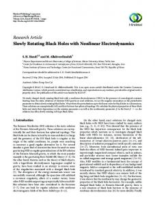
Fig. 2. Non-rotating and rotating unit vector systems.
arises for the rotating rotor blade problem is whether these higher order non-linearities can also play a significant role in the equilibrium and stability of the elastic motion of the rotating blade. In this paper, the work presented in [6, 7, 13, 15] is extended with the objective of formulating a systematic set of differential equations of motion for both extensional and inextensional rotating beams and helicopter rotor blades, with pre-cone and a pitch angle, including cubic non-linearities. The equations developed here are used in Part II of this paper to analyze the response of a helicopter rotor blade in hover and to determine the influence of several higher order non-linear terms in the equilibrium and stability of the elastic motion of the blade. THE DYNAMIC SYSTEM AND BASIC ASSUMPTIONS
Consider an initially straight, pre-twisted, rotor blade of undeformed length R, mass m per unit length, and of closed cross section. Its maximum cross section dimension is assumed to be much smaller than R so that it may be approximated as a beam. A blade segment, both in its undeformed and deformed states, is shown in Fig. 1. The Ce. 17, 0 axes, with unit vectors indicated in bold type with a~ are the principal axes at the elastic center C, of the deformed blade cross section at x = x; it is assumed that the cross section is symmetric about the 17-axis. Thee-axis is tangent at all times to the elastic axis of the blade. Prior to elastic deformations, C, is at location (x = x, y = 0, z = 0). The (x, y, z) axes, with unit vectors also indicated in bold type with a·, are a set of hub-fixed rotating reference axes as shown in Fig. 2. The x-axis is coincident with the elastic axis of the undeformed blade. These axes rotate in space with angular velocity n about a direction perpendicular to the rotor hub. The orientation of (x, y, z) relative to a set of inertial (X, Y, Z) axes, also shown in Fig. 2, may be described by first aligning (x, y, z) with (X, Y, Z) and then performing two successive rotations. The first rotation I/I = Ot (where t denotes time) about Z brings the (x, y, z) triad to its new orientation (X1, Y,, Z 1 = Z), while a second rotation P- the blade's constant pre-cone angle-aoout the negative Y, direction (i.e., a clockwise rotation) brings (X,, Y,, Z 1) to the final orientation of (x, y, z ). For simplicity, the blade root offset e, shown in Fig. 2 will be taken to be zero. The angle a., shown in this figure is the angle of attack of the rotor. The principal axes (17, 0 of the blade's cross section at C, make an angle (} (x, If;) with two cross section non-principal axes (17 3 , ( 3 ) shown in Fig. 1. It is assumed that the geometric pitch angle of the blade, (} (x, I/I), is given as
e (x, I/I) = ec + Op1 (x)
n
+ I,
[O;c cos(il/I) + O;, sin(ilf; )]
(1)
i= I
where (Jc is the constant collective pitch angle, (JP1(x) is a pre-twist angle that may be incorporated to the blade, and O;c and O;, (i = 1, 2, ... , n) are the harmonic pitch components that may be
Nonlinear flexure and torsion of rotating beams
153
x'
.
~,L· -Y'
{, x'
Fig. 3. Three-axes orientation angles rotation sequence.
introduced by a control system. When the blade is elastically undeformed, the non-principal 17 3 and ( 3 cross section axes are parallel to the rotating y and z axes, respectively. Due to elastic deformations, the elastic center of the pitched undeformed blade's cross section at x = x shown in Fig. I, moves from (x = x, y = 0, z = 0) to a new location whose coordinates relative to the rotating (x, y, z) axes are written, respectively, as Rx+ Ru(x, l/J), Rv(x, l/J) and Rw (x, I/I). Here, (u, v, w) are the (x, y, z) components of the elastic displacement vector of the blade's cross section elastic center, non-dimensionalized by R. In general, each cross section of the blade experiences the elastic displacements Ru (x, l/J ), Rv (x, l/J) and Rw(x, l/J) of its elastic center c. and a rotation about c•. The orientation of the cross section principal axes (~, 17, O centered at c. may be described by three successive rotations. The set of three-axes orientation angles shown in Fig. 3 is used here for this purpose. We begin this process by aligning((, ii,() with (x, y, z) and then performing the three successive rotations shown in Fig. 3. The first rotation 8, (x, l/J) about z brings((, ii,() to((,, ii 1 , (, = z). The second rotation By(x, l/J) about the negative direction (a clockwise rotation) of the new position iii of the ii unit vector brings (~i, iii, Ci) to ((2 , iii= iii , ( 2 ). A third rotation Bx(x, I/I) about ( 2 = (brings this triad to ((, ii 3 , ( 3 ). As indicated in Fig. 1, an additional rotation of the ((, ii 3 , ( 3 ) triad by an amount equal to the pitch angle 8 (x, l/J) about ~ brings the blade's cross section principal axes to their actual orientation in space. The elements t ij of the transformation matrix [T] between (x, y, z) and ((,ii,(), defined as (2)
may be readily obtained with the aid of Fig. 3. As pointed out in [6, 12), the advantage of incorporating the pitch angle e(x, I/I) as described above, is that it simply shows up in the equations as an additive term to the third orientation angle 8x(x, i/J ). With the position vector of the elastic center C., relative to the hub center 0, given as
r. = R[(x
+ u)x + vy + wz]
(3)
it follows that ~
= ar. /8(Rr) = [(l + u' )x + v'y + w'z] 8x /8r = (xce, + ys8, )c8y + zsey
(4)
154
MARCELO
R.
M. CRESPO DA SILVA
and
DEWEY H . HODGES
where ( )' = o ()/ox, and s() and c(J are used to denote sin() and cos(), respectively. The scalar quantity r denotes arc-length, non-dimensionalized by R, measured along the elastic axis. Since ! is a unit vector, it follows from equation (4) that ox /or= [(1
+ u' )2 + v' 2 +
w' 21- 1' 2
(5)
By letting dots denote partial differentiation with respect tot/I, i.e. ( ). = o( )jot/I, the angular velocity w (x, t/I) of the principal axis system, relative to the inertial frame Y, Z), is obtained directly from Figs 1, 2 and 3 as
ex,
w = !l[B 1 + (B, + c{J)s()Y+ s{Jc()Yc(), ]! + !l[(B, + c{J)s() 1c()Y- Byc() 1- (c() 1s(), + s() 1s()Yc(),)s{J]rj
+ !l[(B, + c{J)c() 1c8Y+ Bys() 1+ (s8 1s8, - c() 1s()Yc8, )s{J]( (6)
where () 1 = ()(x, t/I) + ()x(x, t/I), and £ denotes "equal by definition". Similarly, the components of the elastic axis curvature vector C(x, t/I ), non-dimensionalized by R, can be readily obtained from Fig. 3 and equation (6) as RC= [(} ; z - (J ~ rj 1
+ e;!J ox /or
= [(); + e; sey](ox /or)! + [e ; s81c8y- () ~ c81](ox /or)rj + [8 ; c81c8y + () ~s8i](ox /or)( £[Pe!+ p~rj
+ p,(](ox /or)
(7)
Although a total of six dependent variables (u, v, w) and (Bx, ()Y ' (), )have been introduced, only four are needed to describe the motion. As seen from equation (4), the angles 8, and ()Y are related to the spatial derivatives of u, v and w as tan
e, = v'/(1 + u')
(8a)
sin ()Y= w' (ox /or) = w' [(l
+ u' )2 + v' 2 + w' 2] - 112
(8b)
The differential equations of motion for the blade will be developed here in terms of the elastic displacements u, v and w, and of the third orientation angle ()x · The extended form of Hamilton's principle [16- 18) will be used to obtain such equations and their boundary conditions. For this, the expressions for the kinetic and strain energies of the motion are formulated next. Due to warping, the position of an arbitrary point P of the cross section through C, experiences a small axial displacement given approximately as -[RA (17, 0)( Peox /or)!, where A (17, O is the warp function, normalized by R, obtained by solving Laplace's equation for the cross section [18). In terms of the non-dimensional coordinates 17 and ( (along the 17 and ( axes, respectively), the position vector of P relative to the hub center 0 is then given as rp
= r, + R (17rj + ~!) -
RApe(ox /or)!
(9)
Assuming that the velocity of the hub center 0 is constant, which is an assumption valid for both cases of hover and non-accelerated forward flight, the kinetic energy of the motion of the blade is then calculated as 2
3
T=!n R
f=
JJp(drp /dt/l)·(drr /dt/l)d17d(dx
(10)
0
A
where pis the blade's material density at point P, and A is the undeformed blade's cross sectional area, normalized by R 2 • To simplify the formulation, it will be assumed that the blade's cross section has material symmetry about the 17-axis so that
If A
and that the warp function A ('q,
p( d17 d(
=
II
Pl'/( d17 d(
=0
(1 la)
A
O satisfies the following relations (11 b) A
A
Nonlinear flexure and torsion of rotating beams
155
With the aforementioned assumptions, and making use of the elements t ij of the transformation matrix [T] defined by equation (2), the kinetic energy may be expressed as
T /(m '1 2 R 3 ) =
1
11
vc{J) 2+[ti + (x + u) c{J - ws{J]2 + (w + vs[J )2} dx
2Jo M {(u -
f
1
+
e {(u -
vc{J)(i21 -
0
t22 c/J) + (w + vs{J)(i23 + t22s{J)
+ [ti+ (x + u)c{J - ws{J](i22 + t 21c{J
t23 s{J)} dx + T*
-
(12)
where m and M (x) are given as
mM(x) = R
2
ff
Lff 1
p d17 d(;
m = R
2
A
p d17 d( dx
(13a, b)
A
Note that if the blade is uniform [ p (x ) =constant] and with constant cross section along its span, M(x) = 1. The contribution T* to the normalized kinetic energy depends on the warping function and is given in the Appendix. The quantities e and}. (ex= 17 , 0 are cross section integrals defined as
e,
me= R
2
ff ff
Pr/ d17d(;
A
mJ, = R 2
mj~ = R 2
ff
2
p( d17 d(
A
2
p17 d17 d(;
j~ = j~ +Jc
(14a- d)
A
To obtain the expression for the strain energy of the deformed blade, a strain tensor, represented here by a matrix [£] with elements £ij is needed. As a measure of the deformation of the blade, the square of the distances between two infinitesimally close points on the blade, before and after deformation, is used [6, 18]. The nonlinear strain-displacement relations for the deformed blade are sought for the case of large displacements but small enough strains so that Hooke's law relating the stresses at any point Pis still valid. Because of the pre-twist of the blade, a strain definition and corresponding strain energy expression should be used that are appropriate for a curvilinear coordinate system [19] . However, according to the results of [19], the presentapproach (similar to that of [6]) yields nearly identical results and is considerably simpler for slender beams with thin cross sections. Since comparison with results generated from the equations derived in [6] is anticipated in Part II of this paper, it is somewhat advantageous to use the same approach. With these assumptions, the matrix [£] is determined as (15)
where rp 0 = rp(u = v = w = ()x = 0). Neglecting in-plane cross section distortion [6], the strain components are readily obtained by making use of equations (15), (9), (3) and (2). With a ij denoting the stresses acting on the blade, the strain energy is given as 3
U= R 2
f
1 J.J[a11£11
x= O
+