Indian Geotechnical Conference 2017 GeoNEst 14-16 December 2017, IIT Guwahati, India
Nonlinear Static Behavior of RC-Building Frame under Lateral Loads Considering Soil Structure Interaction Effects Nishant Sharma Kaustubh Dasgupta Arindam Dey Department of Civil Engineering, Indian Institute of Technology Guwahati, Guwahati – 781039 E-mail :
[email protected];
[email protected];
[email protected]
ABSTRACT: The present article studies the nonlinear behavior of RC building frame under lateral loads by incorporating soil structure interaction (SSI) effects. Nonlinear static pushover analysis of the frame is conducted under different soil conditions. The study highlights the importance of considering SSI into the study. It has been found that incorporating SSI alters the behavior of the super structure and results in higher super structure capacity. Keywords: Pushover; Soil Structure Interaction; RC Frame Building
sections explain the modelling and other details of the study
1. Introduction The Indian seismic design code IS 1893: Part I (2002), and past research suggests ignoring soil structure interaction effects. For the purpose of design and analysis of the structure, the present norm followed is to proceed by neglecting the flexibility provided by the soil foundation system. However, Mylonakis and Gazetas (2000) have rendered such assumptions to be over simplistic as it is imperative that the interaction effects exists and can be detrimental for the structure. In the event of an earthquake significant lateral forces are induced into the structure and the presence of the flexibility, due to the foundation soil system, significantly modifies the global and local lateral load behavior of the structure. Pushover analysis is an effective tool, which can be employed for the analysis of the lateral load behavior of structures under the influence of soil structure interaction effects. For low rise structures it is a common practice to conduct nonlinear static pushover analysis conforming to the first mode deformation shape of the structure. The objective of the present article is to study the lateral load behavior of reinforced concrete building frames supported on pile foundation-soil system.
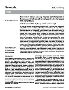
2.1 Structural System Fig. 1 shows the soil-pile-structure system considered, in which the superstructure is a five storey-five bay RC building frame having a uniform bay length and storey height. The structure has been designed and detailed using IS 456 (2000), IS 13920 (1993) considering the imposed and lateral loads using IS 875: Part 2 (1987) and IS 1893: Part I (2002). The section details of column and beams is shown in Table 1. M25 grade of concrete and Fe 415 grade of steel has been used. The frame members have been modelled using two noded force based beam column elements. Table-1 RC frame section details Member Size (mm2) Beam
250×400
Column
400×400
Main r/f Shear r/f l 4@20 mm φ (+) 2 , 8 mm@ 100$ 4@20 mm φ (-) 3l, 8 mm@ 8@ 16 mm φ Uniformly distributed 75*;@200**
$Uniform
spacing of stirrup in mm; *Spacing of stirrup near ends of member in mm; **Spacing of stirrup in elsewhere in member in mm; (+) Tension reinforcement; (-) Compression reinforcement; φ=dia.
2.2 Soil foundation system Rectangular sandy soil domain of length 4 times the structural base width is considered. Bedrock is assumed to be at a depth of 30m from the surface of the ground. Four noded quadrilateral elements, with bilinear isoparametric formulation, has been used to model the soil as continuum. A non uniform meshing has been adopted to appropriately capture the soil behavior in the region of interest. In total 3636 nodes and 3500 elements have been used for the representation of the soil. The size of the smallest element used is 0.25m. Fig. 1 shows the discretized numerical model of the soil-pile-structure system. As in the entire study, dynamics of wave propagation is not being considered therefore radiation boundaries are not being assigned to the model. The horizontal base boundaries are assigned with vertical and horizontal restraints. The vertical boundaries however cannot be assigned with restraints, as this would not allow the system to be pushed
Fig. 1 Numerical model of the soil-pile-structure system 2. Modelling and Input Two-dimensional modelling of the RC building frame has been carried out in OpenSEES, a finite element based software framework, Mazzoni et al (2006). Following sub 1
Nonlinear Static Behaviour of RC-Building Frame under Lateral Loads Considering Soil Structure Interaction Effects
in the deformation shape corresponding to the first mode. Moreover, to develop sufficient strength in the soil, it is required to develop confining condition, as that would be the case on a real site. Therefore, the vertical boundaries are assigned with horizontal reactions obtained after conducting a preliminary nonlinear gravity analysis of the entire soil-pile-structure system for various soil conditions.
3.2
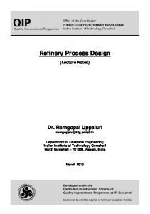
3.2.1 Material nonlinearity Stress strain data for confined and unconfined concrete has been obtained by the relationships prescribed Chang and Mander (1994) and they are shown in Fig 2. The stress strain relationship used to model the reinforcing steel is shown in Fig 3, Filippou et al (1983). These stress strain data are assigned to the fiber section used to model the RC section of beams and columns.
Pile foundations has been used for supporting of the structure on the soil medium. The lateral force estimation and design of pile group has been done using IS 2911: Part I/Sec I (1979) and other relevant Indian standards. Since, not much nonlinearity is expected to arise in the pile groups, the pile elements are assigned linear elastic sectional properties. The piles are connected to the soil elements using zero length rigid link member and interface nonlinearity has not been considered. The pile groups are connected to each other using grade beams of size 0.4m×0.4m.
. 30
Stress (MPa)
25
Table-2 Basic soil properties Soil Type
ρ(t/m3)
Soft soil (SS) Med Soil (MS) Med Dense Soil(MDS) Dense Soil (DS)
1.7 1.9 2.0 2.1
φ
ν
e Gr(kPa)
Unconfined Concrete
0.2
0.4 Strain (%)
0.6
0.8
500 400
Stress (MPa)
Length (m) 8.0 7.0 6.0 5.0
Confined Concrete
Fig. 2 Stress strain relation of concrete
n
300 200 100
3 3 3 3
Fe 415
0 0.0
0.2
0.4
0.6 Strain (%)
0.8
1.0
1.2
Fig. 3 Stress strain relation of rebar steel
n= number of piles in a group
3.2.2 Plastic hinge The nonlinearity in the building frame is considered in the form of plastic hinges that develop over a length at the ends of the member. The length of the plastic hinge for the members is obtained using the relationship shown in Equation 1 proposed by Paulay and Pristley (1992).
In the present study, four different types of soil have been considered and for each soil condition, the pile groups have been designed. In practice it is common to keep the diameter of the piles same for various locations and to adjust the length of the piles for obtaining appropriate load capacity of the pile foundation. Therefore, in the present study, the pile groups for different soil conditions have been designed keeping the diameter as 0.5m and appropriate lengths. Table 2 shows the basic soil properties considered and Table 3 shows the details of pile groups designed. 3.
10
0.0
5.5×10⁴ 7.5×10⁴ 1.0×10⁵ 1.3×10⁵
Table-3 Pile group details
Soft soil (SS) Med Soil (MS) Med Dense Soil(MDS) Dense Soil (DS)
15
0
ρ= Density; φ=Friction angle; ν= Poisson’s ratio; Gr is reference low strain shear modulus measured at 80 kPa reference pressure
Soil Type
20
5
29 0.33 0.85 33 0.33 0.70 37 0.35 0.55 40 0.35 0.45
Dia. (m) 0.5 0.5 0.5 0.5
Structural nonlinearity
l p 0.08l 0.022d b
(1)
The assignment of plastic hinge length ensures that the nonlinearity developed in the building frame members is localized in the end regions. Nonlinear pushover analysis by assigning plastic hinges is a very standard procedure and is extensively practiced in the present day research community.
Nonlinear Behaviour
3.1 Soil nonlinearity PressureDependMultiYield material has been used to simulate the nonlinear behavior of the soil. The plastic behavior in this material model follows the DruckerPrager yield surfaces (nested yield surface) criteria. The basic soil properties are shown in Table 2.
4. Eigen Analysis To conduct displacement controlled pushover analysis it is mandatory to define a lateral load pattern in which the structure needs to be pushed. For low rise structure, the participation of the first mode shape is of the order of 90% in the response. Therefore, in the event of an earthquake, 2
Indian Geotechnical Conference 2017 - GeoNEst 14-16 December 2017, IIT Guwahati, India
it is the most likely mode to get excited. Hence, in the present study the profile of the lateral load pattern corresponds to the first mode shape in which the structure will deform. For this eigen analysis of the soil-pile structure system is conducted to obtain the deformed profile of the structure. Fig. 4 shows the comparison of first mode shape of the structure for different soil conditions with that of the structure to be founded on rock (represented by R). The lateral load pattern on the structure for various soil conditions are applied in the shape corresponding to their modal deformed shapes.
510
18
SS MS MDS DS R
15
459 408
12
Shear (kN)
Height of Structure (m)
various columns locations (1 and 6 are exterior columns; 2,3,4 and 5 are interior columns). The relative settlement between the pile groups supporting the interior and exterior columns increased form 0.7 mm for dense soil to 1.2 mm for soft soil. This relative settlement gives rise to additional moments in the beams of the building frame which result into higher shear forces in them. These additional shear forces are transferred to the columns thereby increasing the axial loads in them. The increase in the axial load is proportional to the amount of relative settlement.
9
357 306 255 SS MS MDS DS R
204
6
153
3
102 0.00
0.02
0 0
0.2
0.4 0.6 0.8 Relative Displacement
1
0.04 0.06 0.08 T op storey Drift (mm/mm)
0.10
1.2
Fig. 5 Pushover curves for different soil conditions
Fig. 4 Modal shapes as lateral load pattern
5.2 Local behaviour Fig. 6 shows the axial forces developed in the ground storey columns of the structure, under gravity loads, for various soil conditions and its comparison with those developed under rocky condition. It can be observed that for the structure supported on all types of soil, the exterior columns sustain larger axial force when compared with those for rocky condition. For interior columns however the opposite is the case, i.e., the interior columns for various soil conditions sustain lesser force in comparison with those for rocky condition. This can be attributed to the vertical settlements of the pile group supporting the columns. Fig. 7 shows the vertical settlement of the soil at
200 R
150
DS MDS
100
MS 50
SS
0 1
2
3 4 Column Location
5
6
Fig. 6 Axial force in ground storey columns 1
2
Column Location 3 4
5
6
-16
Settlement (mm)
5.1 Global behaviour Fig. 5 shows the shear developed at the base of the columns, just above pile top, versus the roof displacement in the structure for various soil conditions. It can be seen from the curve that for rocky condition, the lowest capacity is observed and for soft soil highest. The percentage increase in the capacity of the structure is 8.6% for soft soil (SS), 7.6% for medium soil (MS), 6.5% for medium dense soil (MDS), and 5.2% for dense soil (DS) when compared with that for rocky condition. The initial stiffness of the structure however remains similar for all the soil conditions when compared with that of rocky condition.
250
Axial Force (kN)
5. Results and Discussion: Pushover Analysis Following the eigen analysis, pushover analysis of entire soil pile structure system is conducted for various soil conditions. The behavior of the building frame is studied by comparing the results with that obtained for the structure supported on rock.
-20
DS
-24
MDS
-28
MS
-32
SS
-36 -40
Fig. 7 Pile group settlement at column base 5.3 Increase in sectional capacity The axial force in the exterior columns is increased due to the relative settlement of the plie groups supporting the columns. Under the applied lateral load, the axial load in exterior column 1 is reduced and that in the exterior
3
Nonlinear Static Behaviour of RC-Building Frame under Lateral Loads Considering Soil Structure Interaction Effects
sections thereby increasing the global superstructure capacity. The study highlights the importance of considering the effect of soil structure interaction.
column 6 is increased greatly. This is because the lateral load tries to uplift the pile group under exterior column 6 and consequently the pile tries to balance the gravity load of the pile group by taking up higher axial forces. Fig. 8 and Fig. 9 shows the distribution of the axial load in the various ground storey columns for various soil conditions at 0.04m and 0.5m top roof lateral displacement of the structure. It can be seen that the exterior column 1 very quickly goes into tension and the rate is highest for rocky condition and lowest for soft soil. Once the exterior columns are under tension, the failure of these columns is accelerated due to a reduction of mobilized moment capacity. Fig. 10 compares the change in the mobilized moment curvature behavior (of ground storey exterior column 1) for soft soil (SS) and rocky condition (R). It can be seen that the capacity of the section is reduced due to the reduction in the axial compressive force. The same behavior is observed for columns at higher storey as well and the cumulative effect leads to higher superstructure capacity when supported by soil as compared to that when supported by rocky condition.
110
Moment (kNm)
100
Axial Force (kN)
Filippou, F.C., Popov, E.P., Bertero, V.V. (1983) Effects of Bond Deterioration on Hysteretic Behavior of Reinforced Concrete Joints, Report EERC 83-19, Earthquake Engineering Research Center, University of California, Berkeley.
MS SS
50
IS 13920 (1993) Indian Standard Ductile Detailing of Reinforced Concrete Structures Subjected to Seismic Forces- Code of Practice, Bureau of Indian Standards, New Delhi, India
0 -50
1
2
3
4
5
6
Column Location
Fig. 8 Axial force in ground storey columns for 0.04 m
IS 1893: Part I (2002) Indian standard criteria for earthquake resistant design of structures, fifth revision, Bureau of Indian Standards, New Delhi.
roof displacement
IS 2911: Part I/Sec 1 (1979) Indian standard code of practice for design and construction of pile foundations, first revision, Bureau of Indian Standards, New Delhi.
500
Axial Force (kN)
400 R
300
IS 456 (2000) Indian standard plain and reinforced concrete- code of practice, fourth revision, Bureau of Indian Standards, New Delhi.
DS
200
MDS 100
MS
0 1
2
3
4
5
6
IS 875: Part 2 (1987) Indian Standard Code of Practice for Design Loads (Other than Earthquake) for Building and Structures: Imposed Loads, Bureau of Indian Standards, New Delhi, India.
SS
-100 -200
0.45
Chang, G. and Mander, J. (1994) Seismic Energy Based Fatigue Damage Analysis of Bridge Columns: Part I – Evaluation of Seismic Capacity, NCEER Technical Report 94-0006.
MDS
100
0.15 0.30 Curvature (per m )
References
DS
150
SS R
Fig. 10 Axial force in ground storey columns
R
200
70
50 0.00
350
250
80
60
400
300
90
Column Location
Mazzoni, S., McKenna, F., Scott, M.H. and Fenves, G.L. (2006) OpenSees command language manual, Pacific Earthquake Engineering Research (PEER) Center.
Fig. 9 Axial force in ground storey columns for 0.5 m roof displacement
Mylonakis, G., Gazetaz, G. (2000) Seismic soil-structure interaction: Beneficial or detrimental?, Journal of Earthquake Engineering, 4(3), pp. 277-301.
6. Conclusions Pushover analysis of a five storeyed building frame was carried out to study its lateral load behavior considering soil structure interaction. The study highlights the effect of considering soil in the lateral load behavior of RC building framed structure. The flexibility provided by the soil alters the behavior of the structure when compared to the structure supported on rocky condition. The altered behavior is responsible for increased capacity of the frame
Paulay, T., and Priestley, M.J.N. (1992) Seismic design of reinforced concrete and masonry buildings, John Wiley & Sons Inc., USA
4