Many problems in computational science arise in unbounded domains and thus require an artificial boundary B, which truncates the unbounded ex-.
Nonreflecting Boundary Conditions for Time-Dependent Wave Propagation
Inauguraldissertation zur Erlangung der Würde eines Doktors der Philosophie vorgelegt der Philosophisch-Naturwissenschaftlichen Fakultät der Universität Basel
von
Imbo Sim aus Suwon (Südkorea)
Lausanne, 2010
Genehmigt von der Philosophisch-Naturwissenschaftlichen Fakultät auf Antrag von Prof. Dr. Marcus J. Grote Prof. Dr. Thomas Hagstrom (Southern Methodist University) Basel, den 26. Mai 2009 Prof. Dr. Eberhard Parlow Dekan
Abstract Many problems in computational science arise in unbounded domains and thus require an artificial boundary B, which truncates the unbounded exterior domain and restricts the region of interest to a finite computational domain, Ω. It then becomes necessary to impose a boundary condition at B, which ensures that the solution in Ω coincides with the restriction to Ω of the solution in the unbounded region. If we exhibit a boundary condition, such that the fictitious boundary appears perfectly transparent, we shall call it exact. Otherwise it will correspond to an approximate boundary condition and generate some spurious reflection, which travels back and spoils the solution everywhere in the computational domain. In addition to the transparency property, we require the computational effort involved with such a boundary condition to be comparable to that of the numerical method used in the interior. Otherwise the boundary condition will quickly be dismissed as prohibitively expensive and impractical. The constant demand for increasingly accurate, efficient, and robust numerical methods, which can handle a wide variety of physical phenomena, spurs the search for improvements in artificial boundary conditions. In the last decade, the perfectly matched layer (PML) approach [16] has proved a flexible and accurate method for the simulation of waves in unbounded media. Standard PML formulations, however, usually require wave equations stated in their standard second-order form to be reformulated as first-order systems, thereby introducing many additional unknowns. To circumvent this cumbersome and somewhat expensive step we propose instead a simple PML formulation directly for the wave equation in its second-order form. Our formulation requires fewer auxiliary unknowns than previous formulations [23, 94]. Starting from a high-order local nonreflecting boundary condition (NRBC) for single scattering [55], we derive a local NRBC for time-dependent multiple scattering problems, which is completely local both in space and time. To do so, we first develop a high order exterior evaluation formula for a purely outgoing wave field, given its values and those of certain auxiliary functions 1
needed for the local NRBC on the artificial boundary. By combining that evaluation formula with the decomposition of the total scattered field into purely outgoing contributions, we obtain the first exact, completely local, NRBC for time-dependent multiple scattering. Remarkably, the information transfer (of time retarded values) between sub-domains will only occur across those parts of the artificial boundary, where outgoing rays intersect neighboring sub-domains, i.e. typically only across a fraction of the artificial boundary. The accuracy, stability and efficiency of this new local NRBC is evaluated by coupling it to standard finite element or finite difference methods.
2
Acknowledgements This work was supported by the Swiss National Science Foundation under projects, Advanced Methods for Computational Electromagnetics (NF–Nr. : 200020 − 105135, 200020 − 113702). My sincere thanks go to Prof. Marcus J. Grote for his indispensable support during my doctoral studies and all his patience. His excellent knowledge and experience of computational wave propagation have always been a great source of motivation for me. I’m very grateful to Prof. Thomas Hagstrom for his interest in my work, and for his willingness to act as a co-referee for my thesis. I wish to express my warmest and deepest gratitude to my family as well for their support as for their patience during my study abroad.
3
Contents 1 Introduction to Wave Propagation in Unbounded Domains 1.1 Nonreflecting boundary conditions on planar boundaries . . . . . . . . 1.1.1 Engquist - Majda . . . . . . 1.1.2 Higdon . . . . . . . . . . . . 1.1.3 Givoli - Neta . . . . . . . . 1.1.4 Hagstrom - Warburton . . . 1.2 Nonreflecting boundary conditions on spherical boundaries . . . . . . . 1.2.1 Bayliss - Turkel . . . . . . . 1.2.2 Grote - Keller . . . . . . . . 1.2.3 Hagstrom - Hariharan . . . 1.3 Perfectly matched layers (PML) . . 1.3.1 Split formulation . . . . . . 1.3.2 Unsplit formulation . . . . .
11 . . . . .
. . . . .
. . . . .
. . . . .
. . . . .
. . . . .
. . . . .
. . . . .
. . . . .
. . . . .
. . . . .
. . . . .
. . . . .
. . . . .
. . . . .
12 12 12 12 13
. . . . . . .
. . . . . . .
. . . . . . .
. . . . . . .
. . . . . . .
. . . . . . .
. . . . . . .
. . . . . . .
. . . . . . .
. . . . . . .
. . . . . . .
. . . . . . .
. . . . . . .
. . . . . . .
. . . . . . .
13 13 13 15 17 17 18
2 On Local Nonreflecting Boundary Conditions for Time Dependent Wave Propagation 2.1 Introduction . . . . . . . . . . . . . . . . . . . . . . . . . . . . 2.2 Absorbing boundary conditions . . . . . . . . . . . . . . . . . 2.2.1 The One-dimensional Wave Equation . . . . . . . . . . 2.2.2 Absorbing Boundary Conditions in Higher Dimensions 2.2.3 High-order local nonreflecting boundary conditions . . 2.3 Multiple scattering problems . . . . . . . . . . . . . . . . . . . 2.3.1 The one-dimensional case . . . . . . . . . . . . . . . . 2.3.2 The three-dimensional case . . . . . . . . . . . . . . . . 2.4 Numerical experiment . . . . . . . . . . . . . . . . . . . . . . 2.5 Conclusion . . . . . . . . . . . . . . . . . . . . . . . . . . . . . 4
20 20 23 23 25 31 32 33 35 36 38
3 Perfectly Matched Layers for Time-Dependent Wave Equations in Second-Order Form 3.1 Introduction . . . . . . . . . . . . . . . . . . . . . . . . . . . . 3.2 PML formulation . . . . . . . . . . . . . . . . . . . . . . . . . 3.3 Stability . . . . . . . . . . . . . . . . . . . . . . . . . . . . . . 3.4 Extension to complex frequency shifted PML . . . . . . . . . . 3.5 Discretization . . . . . . . . . . . . . . . . . . . . . . . . . . . 3.5.1 Finite difference discretization . . . . . . . . . . . . . . 3.5.2 Discontinuous Galerkin Discretization . . . . . . . . . . 3.6 Numerical experiments . . . . . . . . . . . . . . . . . . . . . . 3.6.1 Point source in 2D . . . . . . . . . . . . . . . . . . . . 3.6.2 Heterogeneous medium in 2D . . . . . . . . . . . . . . 3.6.3 Point source in 3D . . . . . . . . . . . . . . . . . . . . 3.7 PML for elastodynamic equations in second-order form . . . . 3.7.1 Model problem . . . . . . . . . . . . . . . . . . . . . . 3.7.2 PML formulation . . . . . . . . . . . . . . . . . . . . . 3.7.3 Extension to complex frequency shifted PML . . . . . . 3.7.4 Discretization . . . . . . . . . . . . . . . . . . . . . . . 3.7.5 Numerical experiments . . . . . . . . . . . . . . . . . . 3.8 PML for poroelastic wave equations in second-order form . . . 3.8.1 Model problem . . . . . . . . . . . . . . . . . . . . . . 3.8.2 PML formulation . . . . . . . . . . . . . . . . . . . . . 3.8.3 Discretization . . . . . . . . . . . . . . . . . . . . . . . 3.8.4 Numerical experiments . . . . . . . . . . . . . . . . . . 3.9 Concluding remarks . . . . . . . . . . . . . . . . . . . . . . . .
41 41 43 46 50 52 52 54 55 56 56 58 59 59 61 63 65 67 75 75 76 78 81 81
4 Local Nonreflecting Boundary Conditions for Time-Dependent Multiple Scattering 86 4.1 Local boundary condition for single scattering . . . . . . . . . 86 4.2 Exterior evaluation formula . . . . . . . . . . . . . . . . . . . 87 4.3 Local boundary condition for multiple scattering . . . . . . . . 94 4.3.1 Multiple scattering in spherical coordinate . . . . . . . 94 4.4 Finite difference formulation . . . . . . . . . . . . . . . . . . . 97 4.5 Interpolation of the evaluated solution . . . . . . . . . . . . . 98 4.5.1 Akima spline interpolation . . . . . . . . . . . . . . . . 98 4.6 Numerical experiments . . . . . . . . . . . . . . . . . . . . . . 101 4.6.1 Accuracy of the evaluation formula . . . . . . . . . . . 101 4.6.2 Multiple scattering of an incident plane wave . . . . . . 103 5
5 Time-Dependent Multiple Scattering for Maxwell’s tions 5.1 Local NRBC for single scattering . . . . . . . . . . . . 5.2 Local boundary condition for multipole fields . . . . . . 5.3 Exterior evaluation formula for multipole fields . . . . . 5.4 Time-dependent multiple scattering for Maxwell’s equations . . . . . . . . . . . . . . . . . .
6
Equa105 . . . . 105 . . . . 106 . . . . 110 . . . . 111
List of Figures 1.1 1.2
2.1
2.2
2.3 2.4 2.5 2.6 2.7
2.8
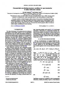
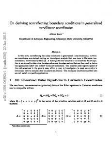
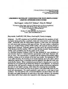
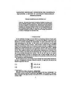
Sphere with a ball-shaped obstacle as a computational domain (the mesh was generated by DistMesh [89]). Nonreflecting boundary condtions are imposed on the outer surface of a sphere. 14 Top: a photonic crystal ([76]) with periodic dielectric holes that affect the propagation of electromagnetic waves. Bottom: numerical solution of the z-component of the time-dependent electric field, Ez , which was implemented with the PML method. The pictures show that the photonic crystal can be used to induce a 90 degree bend in the direction of propagation. . . . . . 19 A typical scattering problem consists of an obstacle, a source term f , and incoming wave ui , and a scattered wave us . The artificial boundary B defines the outer boundary of the computational domain Ω. . . . . . . . . . . . . . . . . . . . . . . . The one-dimensional wave equation: inside the computational domain, Ω = [0, L] the problem can be arbitrarily complicated, but in the exterior region, x ≥ L, we assume that f (x, t) = 0 for t > 0 and that u and ∂t u vanish at t = 0. . . . . . . . . . . A traveling plane wave with an angle of incidence θ. . . . . . . Amount of spurious reflection (in percent) caused by the use of the boundary conditions (2.14) for a plane wave with angle of incidence θ. . . . . . . . . . . . . . . . . . . . . . . . . . . . Multiple scattering in one space dimension. . . . . . . . . . . . Left: the time dependence of the Gaussian point source. Right: the velocity profile c(r). . . . . . . . . . . . . . . . . . . . . . Scattering from a spherical wave guide: snapshots of the reference solution at different times. The three circles drawn are located at r = 0.5, 1, 1.5. The Gaussian point source is located outside the computational domain at r = 0.45, θ = 0. . . . . . The numerical solutions computed using the boundary conditions (4.2) with P = 0, P = 1, and P = 5, are compared with the exact solution at r = 0.75, θ = 3π/4. . . . . . . . . . . . . 7
22
24 29 30 33 37
39 40
3.1 The damping profile ζi(xi ) given by (3.15) is shown for different values of ζ¯i , with c = 1 and Li = 0.1 . . . . . . . . . . . . 3.2 Point source in 2D: snapshots of the numerical solutions at different times in Ω = [−0.5, 0.5]2 , surrounded by a PML of width L = 0.1. . . . . . . . . . . . . . . . . . . . . . . . . . . 3.3 Point source in 2D: time evolution of the L2 –error for different damping coefficients ζ¯i . . . . . . . . . . . . . . . . . . . . . . 3.4 Heterogeneous medium in 2D: varying wave speed c given by (3.51). . . . . . . . . . . . . . . . . . . . . . . . . . . . . . . 3.5 Heterogeous medium in 2D: snapshots of the numerical solution are shown at different times in Ω = [−1, 1]2 , surrounded by a PML of width L = 0.2. . . . . . . . . . . . . . . . . . . 3.6 Point source in 3D: snapshots of the numerical solution are shown at different times in Ω = [−0.5, 0.5]3 , surrounded by a PML of width L = 0.1. . . . . . . . . . . . . . . . . . . . . . 3.7 Left: the orientation of the slowness vector s is the same as the group velocity vs with respect to the direction k1 , Right: the orientations of s and vs are different with respect to the direction k1 (see more details [15]). . . . . . . . . . . . . . . 3.8 Slowness curves for different materials. . . . . . . . . . . . . 3.9 The snapshots of kuk2 in material I . . . . . . . . . . . . . . 3.10 The snapshots of kuk2 in material II . . . . . . . . . . . . . 3.11 The snapshots of kuk2 in material III . . . . . . . . . . . . 3.12 The snapshots of kuk2 in material IV . . . . . . . . . . . . . 3.13 The snapshots of kuk2 in material V . . . . . . . . . . . . . 3.14 Numerical solution, uhs,1 with the pressure source, fp in the computational domain Ω = [−3, 3]2 surrounded by PML of width L = 0.6. It was implemented with finite difference method. . . . . . . . . . . . . . . . . . . . . . . . . . . . . . 3.15 Numerical solution, w1h . . . . . . . . . . . . . . . . . . . . . 3.16 Numerical solution, ph . . . . . . . . . . . . . . . . . . . . .
. 47
. 57 . 57 . 58
. 59
. 60
. . . . . . .
62 68 70 71 72 73 74
. 82 . 83 . 84
4.1 Wave scattering from an obstacle Γ. The computational domain, Ω, is bounded by the artificial boundary, B, where the local NRBC (4.2) is imposed. Subsequent evaluation of the solution in other sub-domains, Q1 and Q2 , is possible via (4.16) by using past values of u and wk at B. . . . . . . . . . . . . . 95 4.2 Local coordinates (r1 , θ1 ) and (r2 , θ2 ) . . . . . . . . . . . . . . 96 4.3 Evaluation of solution on the other computational domain: we evaluate the exterior solution on P2 , P3 , and P4 based on the auxiliary functions on P0 , and P1 . . . . . . . . . . . . . . . . . 98 8
4.4
4.5 4.6 4.7 4.8
We calculate the auxiliary functions, wk , k = 0, . . . , p of HagstromHariharan’s NRBC (4.2) at the green points. Then we obtain the exterior solutions at the blue points, using representation formula (4.39), and if needed, interpolate the exterior solution at the red points using the local spline interpolation (4.50) with (4.59). . . . . . . . . . . . . . . . . . . . . . . . . . . . . 101 Contour lines across B obtained either from the numerical solution for 0.5 ≤ r ≤ 1 or the evaluation formula (4.39) for r > 1; the source is located at (0.4, 0). . . . . . . . . . . . . . . 102 Evaluation of the solution at θ = π2 and t = 1 for varying p. . . 102 The total L2 -error is shown vs. the mesh size h for varying p. . 103 Plane wave scattering from two sound-soft spheres. The computation is restricted to the two disjoint regions. . . . . . . . . 104
9
Dedicated to Hyunmyung & Gyuseong
10
Chapter 1 Introduction to Wave Propagation in Unbounded Domains
Abstract Many problems in computational science arise in unbounded domains and thus require an artificial boundary B, which truncates the unbounded exterior domain and restricts the region of interest to a finite computational domain, Ω. It then becomes necessary to impose a boundary condition at B, which ensures that the solution in Ω coincides with the restriction to Ω of the solution in the unbounded region. If we exhibit a boundary condition, such that the fictitious boundary appears perfectly transparent, we shall call it exact. Otherwise it will correspond to an approximate boundary condition and generate some spurious reflection, which travels back and spoils the solution everywhere in the computational domain. In addition to the transparency property, we require the computational effort involved with such a boundary condition to be comparable to that of the numerical method used in the interior. Otherwise the boundary condition will quickly be dismissed as prohibitively expensive and impractical. The constant demand for increasingly accurate, efficient, and robust numerical methods, which can handle a wide variety of physical phenomena, spurs the search for improvements in artificial boundary conditions. In this section we give a brief review of nonreflecting boundary conditions (NRBC). 11
1.1 1.1.1
Nonreflecting boundary conditions on planar boundaries Engquist - Majda
In the late 1970s, Engquist and Majda [32, 33] contributed to the construction and analysis of a hierachy of local boundary conditions, whose second-order version is still widely used. By using the Laplace-Fourier transform in time and in the plane tangential to the artificial boundary, they derived the exact boundary condition in terms of a pseudo-differential operator, which in practice needs to be localized through a Padé approximation.
1.1.2
Higdon
Higdon [71, 72] derived a Nonreflecting Boundary Condition (NRBC) of the form � p � Y ∂ ∂ cos αj − c u = 0. (1.1) ∂t ∂x j=1 This boundary condition is exact for any linear combination of plane waves whose angles of incidence are ±αj with wave speed c, i.e., each term of the product in (1.1) annihilates the two plane waves u = u(t − cos αj x − sin αj y) and u = u(t − cos αj x + sin αj y). These plane waves leave the computational domain without reflections, but all other waves produce some reflections. Its reflection coefficient is � p � Y cos αj − cos θ (1.2) cos αj + cos θ j=1 for plane waves propagating at the angle of incidence θ. This implies that the reflection coefficient becomes smaller as the order p is increased. The Higdon NRBCs can be applied to a variety of wave problems including those in dispersive or in layered media. We note that Engquist-Majda ABC’s are equivalent to (1.1) for αj = 0, j = 1, . . . , p.
1.1.3
Givoli - Neta
Based on a reformulation of the Higdon NRBCs, Givoli and Neta [43] derive a new boundary scheme, which does not involve any high derivatives beyond second order. In contrast to the exponential computational effort in Higdon’s NRBCs, the effort with the Givoli-Neta NRBCs increases just with the order. 12
1.1.4
Hagstrom - Warburton
Hagstrom and Warburton [58] propose a new formulation of local high-order NRBC with several attractive features in comparison to the Givoli-Neta reformulation of Higdon-NRBC. They introduce new local auxiliary variables, which satisfy a symmetrizable system of second-order wave equations on the absorbing boundary and allows the straightforward derivation of the corresponding high-order corner compatibility conditions.
1.2 1.2.1
Nonreflecting boundary conditions on spherical boundaries Bayliss - Turkel
Bayliss and Turkel [12] derived an alternative sequence of local operators, which annihilate increasingly many terms in the large distance expansion of an outgoing solution to the wave equation. Their boundary condition was extended by Peterson [90] to Maxwell’s equations. The sequence of local operators, which was introduced by Bayliss and Turkel, is as follows: p � Y 1∂ ∂ 2j − 1 � Bp = + + c ∂t ∂r r j=1 �1 ∂ ∂ 2p − 1 � = Bp−1 . + + c ∂t ∂r r
1.2.2
(1.3)
Grote - Keller
The exact NRBC, which is local in time on a spherical boundary, was contributed by Grote-Keller [45, 46] in 1995. It has the following general form �
∂ ∂ + ∂t ∂r
�
N n 1 X X [ru](r, θ, φ, t) = − dn · ψ nm (t)Ynm (θ, φ), R n=1 m=−n
(1.4)
d 1 ψ nm (t) = A ψ (t) + (u(r, θ, φ, t)|r=R, Ynm (θ, φ)) en , dt R n nm ψ nm (0) = 0, 13
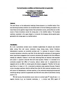
Figure 1.1: Sphere with a ball-shaped obstacle as a computational domain (the mesh was generated by DistMesh [89]). Nonreflecting boundary condtions are imposed on the outer surface of a sphere. with dn = {djn }nj=1 ,
en = {ejn }nj=1,
n An = {Aij n }i,j=1 ,
n(n + 1)j , 2 = δ1j , −n(n+1) , i=1 2 (n+i)(n+1−i) = , i=j+1 2i 0, otherwise,
djn =
(1.5)
ejn
(1.6)
Aij n
and
(u(r, θ, φ, t)|r=R, Ynm (θ, φ)) =
Z2π Zπ 0
(1.7)
u(R, θ, φ, t)Ynm(θ, φ) sin θ dθ dφ, (1.8)
0
14
for an N ≥ 1. Here Ynm are the spherical harmonics: s 2n + 1 (n − |m|)! |m| Ynm (θ, φ) := P (cos θ)eimφ 4π (n + |m|)! n
(1.9)
for m = −n, . . . , n, n = 0, 1, 2, . . . . The spherical harmonics are eigenfunctions of the Laplace-Beltrami operator: (1.10)
∆S Ynm = −n(n + 1)Ynm.
The boundary condition is exact for N → ∞ and local in time, but non-local in space. It is based on the following Fourier representation of the solution u: u(r, θ, φ, t) =
∞ X n X
unm (r, t)Ynm (θ, φ),
n=0 m=−n
unm (r, t) =
Z2π Zπ 0
u(r, θ, φ, t)Ynm(θ, φ) sin θ dθ dφ.
0
This derivation was later extended to electromagnetic and elastic waves [47] - [49].
1.2.3
Hagstrom - Hariharan
According to the expansion theorem of Wilcox [107], the scattered solution of the wave equation can be represented as a series, which converges absolutely and uniformly in r > R: ∞
1 X f k (θ, φ, r − ct) u(r, θ, φ, t) = . r k=0 rk The functions f k = f k (θ, φ, r−ct), f0 by the recursion formula 2k
(1.11)
k ≥ 1, are determined from the function,
∂f k = −(∆S + k(k − 1))f k−1, ∂t
k ≥ 1,
with the Laplace-Beltrami operator � � ∂u 1 ∂2u 1 ∂ sin θ + . ∆S = sin θ ∂θ ∂θ sin2 θ ∂φ2 15
(1.12)
(1.13)
The function f k can be represented by a Fourier series as ∞ X n X
f k (θ, φ, t) =
k fnm (t)Ynm (θ, φ).
(1.14)
n=0 m=−n
Hence, the solution u is expressed as Fourier series: u(r, θ, φ, t) =
∞ X n X
unm Ynm (θ, φ),
r > R,
(1.15)
n=0 m=−n
where the Fourier coefficients
n
k (r − ct) 1 X fnm unm (r, t) = . r k=0 rk
(1.16)
Substituting (1.16) into (1.15) with (1.9),we obtain the recursion formula k fnm k(k − 1) + n(n + 1) k−1 =− fnm , k = 1, 2, . . . . (1.17) dt 2k We consider the sequence of local operators, which was introduced by Bayliss and Turkel p � Y ∂ 2j − 1 � 1∂ + + Bp = c ∂t ∂r r j=1 (1.18) �1 ∂ ∂ 2p − 1 � = Bp−1. + + c ∂t ∂r r Set Bj unm = wjnm . We define the auxiliay functions as
wj (r, θ, φ, t) =
∞ X n X
j ξnm (r, t) Ynm (θ, φ)
(1.19)
n=j m=−n
with j ξnm (r, t)
=
n X k=j
k ajk r −k−j−1fnm (ct − r),
(1.20)
k! where ajk = (−1)j 21−j (k−j)! . Hagstrom and Hariharan [55] use the functions wj to formulate the local boundary conditions: �1 ∂ ∂ 1� u = w1 , + + c ∂t ∂r r � � �1 ∂ 1 � j + wj = 2 j(j − 1) + ∆S wj−1 + wj+1, j = 1, 2, . . . , p, c ∂t r 4r (1.21)
16
with wp+1 = 0. The boundary condition (1.21) is local in space and time and does not involve high-order derivatives. For this reason, this local boundary condition is easily combined with standard numerical methods and enables arbitrarily high order implementations. Recently, it was extended to the time dependent Maxwell equations [53].
1.3 1.3.1
Perfectly matched layers (PML) Split formulation
An alternative to nonreflecting boundary conditions are absorbing layers. We consider the wave equation as a first-order system with the wave speed c = 1 and without source terms: ∂u = ∇ · v, (1.22) ∂t ∂v = ∇u, (1.23) ∂t where v = (v1 , v2 )⊤ . Then Bérenger’s PML formulation [16] is based on splitting the solution, u = ux + uy as follows: ∂v1 ∂ux = , (1.24) ∂t ∂x ∂uy ∂v2 = , (1.25) ∂t ∂y ∂v = ∇u. (1.26) ∂t We now formulate Bérenger’s PML system with damping in the x-direction. Adding the damping terms in the equations involving ux and v1 , we obtain the PML equations: ∂v1 ∂ux + ζux = , (1.27) ∂t ∂x ∂uy ∂v2 = , (1.28) ∂t ∂y ∂u ∂v1 + ζv1 = , (1.29) ∂t ∂x ∂v2 ∂u = . (1.30) ∂t ∂y Inside the absorbing layer a damping term ζ is added to the wave equation, which acts only in the direction orthogonal to the layer. The initial formulations in [16] were based on splitting the electromagnetic fields into two parts, 17
the first containing the tangential derivatives and the second containing the normal derivatives. Damping is then enforced only upon the normal direction. Later Abarbanel and Gottlieb [2] showed that Bérenger’s approach was only weakly well-posed due to the unphysical splitting of the field variables.
1.3.2
Unsplit formulation
The Zhao-Cangellaris formulation [109] avoids splitting the solution, u. Instead, we apply the operator ∂t to (1.27) and the operator ∂t + ζ to (1.28), and add up the two equations: �� � � � � ∂ ∂ ∂ ∂ ∂v1 − +ζ u− + ζ v2 = 0. (1.31) ∂t ∂t ∂x ∂y ∂t The damping parameter, ζ, does not depend on y, and the operators ∂t + ζ and ∂y commute each other. We introduce a new variable, v2∗ , which satisfies the equation ∂v2 ∂v2∗ = + ζv2. (1.32) ∂t ∂t Finally we get the Zhao-Cangellaris formulation ∂u + ζu ∂t ∂v2∗ ∂t ∂v1 + ζv1 ∂t ∂v2 ∂t
∂v1 ∂v2∗ + , ∂x ∂y ∂v2 = + ζv2 , ∂t ∂u = , ∂x ∂u = . ∂y =
(1.33) (1.34) (1.35) (1.36)
In [14] it is shown that the Zhao-Cangellaris formulation is equivalent to the Bérenger’s formulation.
18
Figure 1.2: Top: a photonic crystal ([76]) with periodic dielectric holes that affect the propagation of electromagnetic waves. Bottom: numerical solution of the z-component of the time-dependent electric field, Ez , which was implemented with the PML method. The pictures show that the photonic crystal can be used to induce a 90 degree bend in the direction of propagation.
19
Chapter 2 On Local Nonreflecting Boundary Conditions for Time Dependent Wave Propagation Abstract The simulation of wave phenomena in unbounded domains generally requires an artificial boundary to truncate the unbounded exterior and limit the computation to a finite region. At the artificial boundary a boundary condition is then needed, which allows the propagating waves to exit the computational domain without spurious reflection. In 1977, Engquist and Majda proposed the first hierarchy of absorbing boundary conditions, which allows a systematic reduction of spurious reflection without moving the artificial boundary farther away from the scatterer. Their pioneering work, which initiated an entire research area, is reviewed here from a modern perspective. Recent developments such as high-order local conditions and their extension to multiple scattering are also presented. Finally, the accuracy of high-order local conditions is demonstrated through numerical experiments.
2.1
Introduction
Unbounded domains are often encountered in scientific and engineering applications. Examples are radar and sonar technology, wireless communication, and seismic imaging. Typically the phenomenon of interest is local but embedded in a vast surrounding medium. Although the exterior region may not be truly unbounded, the boundary effects are often negligible, so that one further simplifies the problem by replacing the vast exterior by an infinite medium. Mathematical models of natural phenomena usually consist of partial dif20
ferential equations, whose derivation is based on physical conservation laws. Many standard numerical methods, such as finite differences and finite elements, can approximately solve partial differential equations. In fact, they can even handle complicated geometries, inhomogeneous media, and nonlinearity. However, they typically require an artificial boundary, which truncates the unbounded exterior domain, to fit the infinite region on a finite computer. This immediately raises the question: Which boundary condition guarantees that the solution to the initial-boundary value problem inside the artificial boundary coincides with the solution of the original problem in the unbounded region ? If we exhibit a boundary condition, such that the fictitious boundary appears perfectly transparent, we shall call it “exact”. Otherwise it will correspond to an approximate boundary condition1 and generate some spurious reflection, which travels back and perturbs the solution everywhere in the computational domain. The resulting error in the computer simulation then consists of two independent error components: the discretization error of the numerical method used in the interior and the spurious reflection generated at the fictitious boundary. Unless both error components are reduced systematically, the numerical solution will not converge to the solution of the original problem in the unbounded region. In this article, we shall restrict ourselves to time dependent scattering problems. Typically a scattering problem consists of an obstacle, a source term f , and possibly an incident wave ui – see Figure 1. Scattering problems are common in acoustic, electromagnetic, and elastic wave propagation. Our goal is to calculate numerically the time-dependent wave field us scattered from the complex, possibly nonlinear, but bounded scatterering region. In 1974 Smith suggested perhaps the first exact method to restrict the computation to a finite region [95]. Let the computational domain Ω be bounded by a convex boundary of n line segments (or planar facets in IR3 ). Then the restricition to Ω of the solution in unbounded space consists of a linear combination of 2n solutions which satisfy all possible combinations of Dirichlet or Neumann boundary conditions. Unfortunately, this approach has but little practical value, since a rectangular domain requires 26 = 64 independent numerical solutions. This example illustrates a key aspect in the design of improved absorbing boundary conditions: it is not sufficient to construct a new boundary condition; in addition, the computational effort involved must 1
“...also called radiating, absorbing, silent, transmitting, transparent, open, free-space, and one-way boundary conditions.”, Givoli, 1992 [37]
21
ui
u
s
B
f
Figure 2.1: A typical scattering problem consists of an obstacle, a source term f , and incoming wave ui , and a scattered wave us . The artificial boundary B defines the outer boundary of the computational domain Ω. be comparable to that of the numerical method used in the interior. Otherwise it will quickly be dismissed as prohibitively expensive and impractical. In 1977, Engquist and Majda [32, 33] proposed the first hierarchy of absorbing boundary conditions, which allows a systematic reduction of spurious reflection while keeping the artificial boundary at a fixed distance from the scatterer. Their pioneering work, still very much in use even today, initiated an entire research area that led to a wide variety of different approaches, such as perfectly matched layers (PML) [16], fast integral based formulations [84], semi-local formulations [45, 46] and high-order local conditions [55, 58, 53] – see [56, 104, 39] for review articles and additional references. All these approaches lead to convergent numerical schemes while treating the open boundary at a computational cost comparable to that in the interior. In this article we shall focus on local absorbing (or nonreflecting) boundary conditions, which are completely local both in space and time. First in Section 2, we introduce the fundamental ideas underlying the derivation of nonreflecting boundary conditions by considering the simple one-dimensional case. Next, we review the original Engquist-Majda conditions [32] for wave propagation in more than one space dimensions, where we exhibit the tradeoff between exactness and locality. We also present recent developments of high-order local boundary conditions without high-order derivatives, both for acoustic and electromagnetic waves. Next, in Section 3, we consider the extension of local NBC to multiple scattering, first in one and then in three 22
space dimensions. Finally, in Section 4, we demonstrate the accuracy highorder local conditions via numerical experiments.
2.2
Absorbing boundary conditions
To illustrate the fundamental ideas underlying the derivation of absorbing boundary conditions, we begin with a simple one-dimensional problem. In this special situation many basic notions, in particular the exact boundary condition, appear in a very simple form. Nonetheless, we hasten to point out that its appealing simplicity is also misleading: the real challenges in deriving effective absorbing boundary conditions appear only in higher dimensions. Indeed a one-dimensional wave can only propagate in two directions, to the left or to the right. In two or more dimensions, however, waves propagate in infinitely many directions.
2.2.1
The One-dimensional Wave Equation
Consider the one-dimensional wave equation on the positive real axis, ∂2u ∂2u − 2 = f, ∂t2 ∂x
(2.1)
x > 0, t > 0.
At the left boundary, x = 0, we require that the solution satisfies u(0, t) = 0,
(2.2)
t > 0.
Thus, u(x, t) describes the position of an infinitely (or just very) long vibrating string, attached at its left end; hence, u = 0 corresponds to the state at rest. The one-dimensional wave equation (2.1) describes the propagation of small perturbations induced by the applied forcing f (x, t). Here we have normalized the propagation speed to one by rescaling time appropriately. The initial conditions of the vibrating string are defined by its position and velocity at t = 0: u(x, 0) = U0 (x),
∂ u(x, 0) = V0 (x), ∂t
x > 0.
(2.3)
It can be shown that the initial-boundary value problem (2.1)–(2.3) is wellposed: it has a unique solution, which depends continously on U0 , V0 , and f . We now make the following assumption, which defines the local character of the problem: let the forcing vanish outside a bounded region next to the left boundary, that is let f (x, t) = 0 for x ≥ L and for all time t > 0. Then 23
u
1 x=0
x=L
Figure 2.2: The one-dimensional wave equation: inside the computational domain, Ω = [0, L] the problem can be arbitrarily complicated, but in the exterior region, x ≥ L, we assume that f (x, t) = 0 for t > 0 and that u and ∂t u vanish at t = 0. the positive real line separates into two distinct regions: the bounded interval Ω = [0, L] and the interval [L, ∞), unbounded yet where the forcing vanishes identically. Both regions meet at the artificial boundary {x = L}, which consists only of a single point. Furthermore, we assume that the string is at rest in the exterior at t = 0: U0 (x) = 0 and V0 (x) = 0 for x ≥ L. We now wish to simulate numerically the time dependent behavior of the vibrating string in the computational domain Ω. Unfortunately, we cannot apply our favorite numerical scheme in Ω and simply ignore the new artificial boundary point. On the contrary, we must pay close attention to the new boundary point at x = L: without a boundary condition at x = L, the initial value problem (2.1)–(2.3) restricted to Ω is not even well-posed. To derive a boundary condition, we first need to better understand its role at the artificial boundary. Suppose a wave propagates to the right inside Ω and reaches the right boundary at x = L. It must not be reflected, for any spurious reflection will travel back into the computational domain and spoil the solution everywhere. This spurious reflection, caused by an inaccurate treatment of the artificial boundary, is not due to finite precision, unlike discretization errors present in any computation. If we find a boundary condition, which lets the waves hit the boundary without any reflection, the solution inside Ω, with that boundary condition imposed at x = L, coincides with the restriction to Ω of the solution in the unbounded region. Hence such a boundary condition is exact. Inside the computational domain Ω waves propagate both to the left and to 24
the right. In the exterior region, however, the absence of any forcing and the zero initial conditions preclude the appearance of any waves traveling to the left: there all waves propagate eastward towards infinity – see Figure 2. To derive the exact boundary condition at x = L we first need to separate the incoming from the outgoing waves. To do so, we let v and w be defined by v=
∂u ∂u + , ∂t ∂x
w=
∂u ∂u − . ∂t ∂x
(2.4)
Since u satisfies the wave equation (2.1) in x ≥ L, we conclude that ∂v ∂v − = 0, ∂t ∂x
∂w ∂w + = 0. ∂t ∂x
Thus we can rewrite (2.1) as the first-order hyperbolic system: � � � � � � ∂ −1 0 ∂ v v + = 0. 0 1 ∂x w ∂t w
(2.5)
Its general solution is v(x, t) = φ(x + t),
and
w(x, t) = ψ(x − t),
where φ and ψ are arbitrary functions, which are determined by initial and boundary conditions. Therefore, v is constant on the characteristics x + t = c, whereas w remains constant on the characteristics x − t = c. Thus v corresponds to incoming waves, whereas w corresponds to outgoing waves. Since there are no incoming waves in x ≥ L, we have v(L, t) = 0,
t > 0.
(2.6)
By applying the definition (2.4) of v in (2.6) we thus obtain the exact nonreflecting boundary condition for the displacement u(x, t), � � ∂ ∂ u = 0, x = L, t > 0. (2.7) + ∂t ∂x Note that the problem inside Ω can be arbitrarily complicated, since the derivation of the (exact) nonreflecting boundary condition (2.7) depends only on properties in the exterior region.
2.2.2
Absorbing Boundary Conditions in Higher Dimensions
We consider a highly complex but local scatterer in unbounded two space dimensions. Although we shall restrict ourselves to the two-dimensional 25
case, much of the present discussion carries over immediately to the threedimensional case. Thus we consider the wave equation on the two-dimensional infinite plane, ∂2u ∂2u ∂2u − 2 − 2 = f, t > 0, (2.8) ∂t2 ∂x ∂y with the initial conditions ∂ u(x, y, 0) = U1 (x, y), ∂t
u(x, y, 0) = U0 (x, y),
t = 0.
By scaling time appropriately we have normalized the speed of propagation to one. Again the phenomenon of interest is very complicated, possibly nonlinear, but local. Next, we truncate the unbounded exterior by an artificial boundary and restrict the computation to the square Ω = [−L, L] × [−L, L] – see Figure 1. Outside Ω we assume that neither source terms nor initial perturbations are present: U0 (x, y) = U1 (x, y) = 0,
and
f (x, y, t) = 0, t > 0,
(x, y) ∈ IR2 \ Ω.
Again we seek a boundary condition at (x, y) ∈ B, which ensures that all waves reach the exterior region unharmed and without generating any unphysical reflection at the fictitious interface. Because of symmetry we only need to consider a single edge of the rectangle, here the right edge at x = L. Hence the exterior region lies to the right and the computational domain Ω to the left of the artificial boundary {(x, y) ∈ IR2 |x = L}. Since the initial conditions and the forcing vanish identically in the exterior, all waves in the region x ≥ L are purely outgoing and must propagate eastward. To avoid any spurious reflection at x = L, the exact boundary condition must annihilate all incoming waves. In the previous section we easily derived such an exact nonreflecting boundary condition for the one-dimensional wave equation. Unfortunately, the same approach does not apply in two dimensions. In contrast to the one-dimensional case, any fixed location (L, y) at the artificial boundary receives incoming waves from not one but infinitely many angles of incidence, which propagate in infinitely many directions. The distinction between incoming and outgoing waves is now “infinitely more complicated”. Let uˆ(x, ξ, ω) denote the Fourier transform of the solution u(x, y, t) in time and in the tangential plane, parallel to the artificial boundary, uˆ(x, ξ, ω) =
Z∞ Z∞
u(x, y, t) ei(ωt+ξy) dy dt.
−∞ −∞
26
(2.9)
Here we have set the solution u(x, y, t) to zero for all previous time t < 0. Then u is related to uˆ via the inverse Fourier transform, which resembles (2.9) after exchanging u and uˆ. Since u satisfies the wave equation (2.8) with f = 0 for x ≥ L, its Fourier transform satisfies ∂2 uˆ = (ξ 2 − ω 2 ) uˆ, ∂x2
x ≥ L.
(2.10)
To derive an exact nonreflecting boundary condition at x = L we need to relate the normal derivative – here ∂x u – to tangential and time derivatives –p here ∂y u and ∂t u. From (2.10) we conclude that ∂x uˆ is determined by ± ξ 2 − ω 2 uˆ. The sign in front of the square root discriminates precisely incoming from outgoing waves; here the correct choice leads to the following exact boundary condition: p ∂ uˆ = −iω 1 − (ξ/ω)2 uˆ, ∂x
x = L.
(2.11)
Although this boundary condition ensures the absoute transparency of the artificial boundary, this formulation has but little value in practice. Indeed, we do not seek a boundary condition for uˆ but instead for u. In theory we can always compute the inverse transform and thus determine ∂x u. However, unlike a polynomial expression, whose inverse Fourier transform yields a local differential operator, the inverse transform of the above expression does not result in a simple differential operator because of the square root. Instead, we obtain a so-called pseudo-differential operator, which cannot be evaluated without forward and inverse Fourier transform. As a consequence, the normal derivative ∂x u at any given point on the boundary (L, y) depends on past values of u on the entire line x = L, and cannot be computed locally either in space or time. “...unfortunately, these [perfectly absorbing] boundary conditions have to be nonlocal in both space and time”, Engquist & Majda, 1977 To overcome the difficulties associated with the nonlocal nature of the exact boundary condition (2.11), we can replace the above pseudo-differential operator by an approximate differential operator. In doing so we give up on the absolute transparency of the artificial boundary and accept some spurious reflection. Such absorbing boundary conditions were proposed by Engquist and Majda [32] in 1977, and we now briefly recall the fundamental ideas underlying this popular approach. The Fourier transform of a differential operator always results in a polynomial expression in the frequency domain. For instance the Fourier transform of the 27
differential operator ∂yy yields the polynomial −ξ 2 . Conversely every polynomial in Fourier space corresponds to a (local) differential operator in physical space. Thus, the √ inverse Fourier transform of a polynomial in s = ξ/ω, which approximates 1 − s2 , will yield a differential operator, which can be used as an (approximate) absorbing boundary√condition in physical space. For s sufficiently small, we approximate 1 − s2 by the first few terms of its Taylor expansion: √
1 − s2 = 1 −
s2 + O(s4 ), 2
|s| → 0.
We now replace the√square root in (2.11) by the leading term in the Taylor expansion, that is 1 − s2 ≃ 1, and perform the inverse Fourier transform to obtain ∂ uˆ ≃ −iω uˆ ∂x � � ∂ ∂ u = 0, + ⇒ ∂t ∂x
x = L.
This is the first-order Engquist-Majda boundary condition, which contains only first derivatives of the solution. It coincides with the exact boundary condition (2.7) for the one-dimensional wave equation. Therefore, it remains exact for solutions of the two-dimensional wave equation, which depend only on x and t and thus impinge on the artificial boundary with a normal angle of incidence. Next, we √ include one additional term of the Taylor expansion in the approximation, 1 − s2 ≃ 1 − s2 /2. This yields the second-order Engquist-Majda boundary condition, ∂ uˆ ≃ −iω(1 − (ξ/ω)2/2) u ˆ ∂x � 2 � ∂ ∂2 1 ∂2 ⇒ u = 0, + − ∂t2 ∂x ∂t 2 ∂y 2
x = L.
(2.12)
Equation (2.12) remains exact at normal incidence, since we can rewrite it in the equivalent form as (∂t + ∂x ) (∂t + ∂x ) u = 0,
x = L,
(2.13)
by using (2.8). The inclusion of even higher order terms of the Taylor expansion to improve the accuracy of the approximation ceases to yield well-posed boundary conditions. Although this difficulty can be overcome by the use of rational (Padé) approximations, the high-order derivatives involved in these 28
y
�
x
Figure 2.3: A traveling plane wave with an angle of incidence θ. boundary conditions greatly complicate their use in any numerical scheme. As a result, first- and second-order boundary conditions are most commonly √ used in practice. Various other (e.g. Chebychev) approximations of 1 − s2 were proposed to design improved local boundary conditions. Eventually, Higdon [72] showed that all these boundary conditions are particular cases of the following general class of boundary operators, where α1 , . . . , αp are arbitrary parameters: � � � � ∂ ∂ ∂ ∂ . . . cos α1 u = 0, x = L. (2.14) + + cos αp ∂t ∂x ∂t ∂x For instance, the second-order Engquist-Majda boundary condition (2.13) results from setting α1 = 0◦ and α2 = 0◦ in (2.14). This general formulation, written as the product of first-order differential operators (cos αi ∂t +∂x ), provides a new, more intuitive, interpretation for the effectiveness of absorbing boundary conditions. Since any such differential operator perfectly annihilates plane waves with angle of incidence ±αi , the artificial boundary will appear absolutely transparent at the discrete angles of incidence α1 , . . . , αp . The choice of α1 , . . . , αp is arbitrary and can be adapted to any given situation. Nevertheless, all absorbing boundary conditions remain only approximations to the exact boundary condition (2.11); therefore, they generate some spurious reflection at x = L. How large is the amount of reflection for a specific boundary condition ? Recall that any solution of the (homogeneous) wave equation can be represented by the superposition of plane waves. In Figure 3 29
Re e tion oeÆ ient [%℄ 100 90 80 70
jr j
�1 = 0Æ !
60 50
�1 = �2 = 0Æ
40 30
�1 = 0Æ ; �2 = 60Æ
20 10 0 0
10
20
30
40
50
60
70
80
90
Angle of in iden e � Figure 2.4: Amount of spurious reflection (in percent) caused by the use of the boundary conditions (2.14) for a plane wave with angle of incidence θ.
we observe a plane wave, which impinges on the artificial boundary at x = L with an angle of incidence θ. The linearity of both the wave equation (2.8) and the boundary condition (2.14) imply that any reflected wave necessarily propagates with the same frequency as the incident wave. Hence the solution consists of an outgoing wave, whose amplitude we normalize to one, and an incoming spurious wave with amplitude |r|: u(x, y, t) = ei(kx+ℓy−ωt) + rei(−kx+ℓy−ωt) ,
k, ω ≥ 0,
(2.15)
Here r = r(θ; α1 , . . . , αp ) depends on the angle of incidence θ, defined by tan θ = ℓ/k, and the fixed parameters α1 , . . . , αp . In Figure 4 we compare the effectiveness of three absorbing boundary conditions by displaying the amount of reflection |r| versus the angle of incidence θ. The choice α1 = 0◦ corresponds to the first, whereas α1 = 0◦ und α2 = 0◦ corresponds to the second Engquist-Majda boundary condition. Alternatively, the popular parameter choice α1 = 0◦ and α2 = 60◦ annihilates incoming waves at normal incidence and at 60◦ angle of incidence. All other angles of incidence will generate some spurious reflection, which is very small close to normal incidence but rapidly increases as grazing incidence is approached. 30
2.2.3
High-order local nonreflecting boundary conditions
The local absorbing boundary conditions described in the previous section can be made arbitrarily accurate, but in practice the resulting increasingly higher order derivatives greatly complicate their use in any numerical scheme. As a result, first- and second-order boundary conditions are most commonly used in practice. If even higher accuracy is needed, the artificial boundary then needs to moved farther away from the scatterer. Hence the absorbing boundary conditions from Section 2 do not fully satisfy the demand for increasingly accurate and efficient modern numerical methods to solve complex time-dependent scattering problems in unbounded domains. Starting from a convergent series representation of the scattered field in inverse powers of distance, Hagstrom and Hariharan [55] derived a nonreflecting boundary condition of arbitrarily high order, in the special case when B is a sphere. Thus, let B be the sphere of radius R and assume that u satisfies the homogeneous wave equation, ∂2u − c2 ∆u = 0 ∂t2
(2.16)
with zero initial condition outside B. Starting from the convergent expansion u(r, θ, φ, t) =
∞ X fj (t − r, θ, φ)
rj
j=1
,
r > R,
(2.17)
where r, θ, φ are spherical coordinates, Hagstrom and Hariharan [55] derived the following exact local NRBC: �1 ∂ ∂ 1� u = w1 , (2.18) + + c ∂t ∂r r � �1 ∂ 1 � k� wk = k(k − 1) + ∆ + S wk−1 + wk+1 c ∂t r 4R2 for k = 1, 2, . . ., and w0 = 2u. Here, ∆S denotes the Laplace-Beltrami operator in spherical coordinates (r, θ, φ), ∆S =
∂� 1 ∂2 1 ∂� sin θ + . sin θ ∂θ ∂θ sin2 θ ∂φ2
(2.19)
In fact in 1980, Bayliss and Turkel [12] started from that same infinite series representation and derived a hierarchy of local absorbing boundary conditions in spherical coordinates. Similar to the boundary conditions of Engquist and Majda [32, 33], it also requires increasingly higher order derivatives for improved accuracy. 31
The boundary condition (4.2) is local in space and time yet does not involve high-order derivatives, but instead an infinite sequence of auxiliary variables wk defined on B. In practice, only a finite number of auxiliary functions wk , k = 1, . . . , P is used setting wP +1 = 0. Then, in general the boundary condition is no longer exact, but it remains exact for solutions which consist of a finite combination of vector spherical harmonics up to order P . Imposition of the boundary condition at any fixed radius R thus yields at least spectral accuracy for smooth wave fields with increasing P . Therefore (4.2) is exact in the same sense as the conditions proposed in [45, 46, 47], namely that P can always be chosen sufficiently large so that the error introduced at B is smaller than the discretization error inside Ω, without moving B farther away from the scatterer. However, this new boundary condition does not require any spherical harmonics or inner products with them; hence, it is somewhat easier and cheaper to implement. By combining ideas from [55] and [47], the above approach was recently extended to Maxwell’s equations in three space dimensions [53]. Again, outside B, the medium is assumed to be linear, homogeneous, isotropic, of constant electric permittivity ε, of constant magnetic permeability µ, and of zero conductivity. In addition, we assume that at t = 0 the scattered field is confined to the computational domain inside B. Then, the following exact nonreflecting boundary condition holds [53]: 1 ∂E tan = w1 , (2.20) c ∂t� r � −−→ 1 ∂w 1 w 1 1 −−→ µ 2 + = 2 curlS curlS E + rˆ × curlS curlS H + w(2.21) , c ∂t r 2r ε → 1 ∂w p p p 1 − + w = 2 ( ∆ S +p(p − 1))wp−1 + w p+1 , p ≥ 2. (2.22) c ∂t r 4r
rˆ × curl E −
Again, the boundary condition (2.20)–(2.22) is local both in space and time. It only involves first time derivatives and second tangential derivatives of E and of the (unknown) auxiliary functions w p , p ≥ 1, which satisfy (2.21)– (2.22). Since at least two scalar potentials are necessary to represent the general three-dimensional electro-magnetic field in free space, this boundary condition is optimal in the sense that the number of auxiliary variables required is minimal.
2.3
Multiple scattering problems
When the scatterer consists of several obstacles, which are well separated from each other, the use of a single artificial boundary to enclose the entire 32
scattering region becomes too expensive. Instead it is preferable to enclose every sub-scatterer by a separate artificial boundary Bi . Then we seek an S exact boundary condition on B = Bi , where each Bi surrounds a single computational sub-domain Ωi . This boundary condition must not only let outgoing waves leave Ωi without spurious reflection from Bi , but also propagate the outgoing wave from Ωi to all other sub-domains, which it may reenter subsequently. To derive such an exact boundary condition, an analytic representation of the solution everywhere in the exterior region is needed.
2.3.1
The one-dimensional case t
u1 = u − u2
u2
u1
O Ω1
u2 = u
u1 = u u1
u0
u2 = u − u1
utt − uxx = 0
u2
B1
u0 L x
B2 Ω2
Figure 2.5: Multiple scattering in one space dimension. To illustrate the basic principle underlying the NRBC for multiple scattering problems, we first consider the following simple one-dimensional Cauchy 33
problem: ∂2u ∂2u − 2 = f (x, t), ∂t2 ∂x u(x, 0) = u0 (x), ut (x, 0) = v0 (x).
−∞ < x < ∞,
t > 0, (2.23)
We assume that the initial disturbance and the forcing are supported inside the region Ω = Ω1 ∩ Ω2 , with Ω1 = [0, B1 ] and Ω2 = [B2 , L], 0 < B1 < B2 < L, that is supp{u0, v0 , f (·, t)} ⊂ Ω – see Figure 5. We now wish to restrict the computation to the sub-region Ω; therefore we need to impose appropriate boundary conditions at x = 0, B1 , B2 , and L to ensure that the solution in Ω coincides with the solution u of the original Cauchy problem for all time. Because u is purely outgoing for x < 0 and x > L, the NBC at x = 0 and x = L correspond to the standard artificial boundary conditions for single scattering (see Section 2.1), that is � � ∂ ∂ u = 0, x = 0, − ∂x ∂t � � (2.24) ∂ ∂ u = 0, x = L, + ∂x ∂t
which require no further discussion. We now focus on the two remaining artificial boundary points at x = B1 and x = B2 , where u is not purely outgoing. Because u satisfies the homogeneous wave equation in [B1 , B2 ], it is the superposition of a left and right moving wave there, that is u(x, t) = u1 (x, t) + u2 (x, t),
(2.25)
with u1 (x, t) = f (x − t),
u2 (x, t) = g(x + t).
Moreover, if we require that supp{u1} ⊂ Ω1 and supp{u2 } ⊂ Ω2 at t = 0, u1 and u2 are uniquely defined for all time (see [51]). At x = B1 , an exact NRBC is � � � � � � ∂ ∂ ∂ ∂ ∂ ∂ u= u1 + u2 + + + ∂x ∂t ∂x ∂t ∂x ∂t � � (2.26) ∂ ∂ = u2 , + ∂x ∂t
since u1 is outgoing here. Thus to impose the exact NRBC at x = B1 , we must be able to evaluate u2 there. Here we need to distinguish initial times up to t = B2 − B1 from later times t ≥ B2 − B1 : 34
• 0 ≤ t < B2 − B1 : due to the finite propagation speed (here equal to one) u2 hat not reached Ω1 yet; hence, it is still zero at x = B1 and (2.26) reduces to the standard NRBC for purely outgoing solutions. • B2 − B1 ≤ t: u2 no longer vanishes at x = B1 , however it is fully determined by its past values at x = B2 through u2 (B1 , t) = u2 (B2 , t − (B2 − B1 )).
(2.27)
How do we determine u2 at x = B2 ? Recall that we are only computing u (and not u1 or u2 ) inside Ω. Again, during initial times t < B2 − B1 we have u2 = u at x = B2 . To determine u2 at later times we recall that u(x, t) = u1 (x, t) + u2(x, t),
∀ x ∈ [B1 , B2 ], t > 0.
(2.28)
Therefore we obtain u2 at x = B2 by subtracting from u the value of u1 there, which again is determined by its past values on B1 , that is u2 (B2 , t) = u(B2 , t) − u1 (B2 , t) = u(B2 , t) − u1 (B1 , t − (B2 − B1 )).
(2.29)
Hence in every time step of the numerical scheme, we concurrently update the new values of u1 and u2 at x = B1 , B2 respectively. This requires the additional storage of past values ui at x = Bi , i = 1, 2, for the finite time window [t − (B2 − B1 ), t].
2.3.2
The three-dimensional case
For simplicity, we consider a scattering problem with two bounded disjoint scatterers, each surrounded by a sphere Bi of radius, Ri i = 1, 2. Hence, the entire artificial boundary B = B1 ∪ B2 and the computational domain Ω = Ω1 ∪ Ω2 . In contrast to the situation of single scattering in Section 2, we cannot simply expand u outside B as a superposition of purely outgoing wave fields. In fact, since part of the scattered field leaving Ω1 will reenter Ω2 at later times, and vice versa, u is not outgoing ouside Ω. Thus, the boundary condition we seek at B must not only let outgoing waves leave Ω1 without spurious reflection from B1 , but also propagate those waves to Ω2 , and so forth, without introducing any spurious reflections. Following [51], we first decompose the scattered field u in two wave fields, u = u1 + u2 , where ui is purely outgoing as seen from Ωi . The two wave fields u1 and u2 both solve the homogeneous wave equation (4.1) outside Ω, and their sum coincides with u. The outgoing field uout 1 , as seen from Ω1 , is 35
fully determined by its boundary values on B1 , while the incoming field uin 12 is fully determined by its boundary values on B2 . Hence, in uout 1 + u12 = u|B1 , in uout 2 + u21 = u|B2 ,
(2.30)
where uout is the outgoing wave field from Ωi and uin i ij is the incoming wave propagating from Ωj to Ωi . Next, we apply c−1 ∂t + ∂ri + ri−1 in local spherical coordinates (ri , θi , φi ) to u on each artificial boundary component Bi , i = 1, 2. This yields the following exact local NBC for multiple scattering [54]: �1 ∂ 1 � ∂ B1 u|B1 = + u|B1 + c ∂t ∂r1 R1 in = B1 uout on B1 , 1 + B1 u12 (2.31) � �1 ∂ ∂ 1 u|B2 + + B2 u|B2 = c ∂t ∂r2 R2 in = B2 uout on B2 . 2 + B2 u21
in To evaluate B1 uout 1 we use (4.2) at B1 , whereas to evaluate B1 u12 we use past values for u2 and the corresponding auxiliary functions on B1 . The needed past values of wk are stored on each Bi at regular time and angular intervals and calculated, as needed, via local spline interpolation [54]. Because those values are time-retarded, they are already known, so that the entire scheme remains explicit in time. Remarkably, the information transfer (of time retarded values) between sub-domains occurs only across those parts of the artificial boundary, where outgoing rays intersect neighboring sub-domains, i.e. typically only across a fraction of the artificial boundary.
2.4
Numerical experiment
We shall now illustrate the accuracy of local nonreflecting boundary conditions via the following numerical experiment. Consider a spherical inclusion of radius r0 > 0 located inside an unbounded inhomogeneous acoustic medium. At the sound-soft interface of the inclusion we impose a timedependent pressure field which corresponds to an outgoing spherical wave field, initiated by an off-centered Gaussian point source. Located on the z-axis at distance d < r0 from the origin, its time dependence is shown in Figure 6. Hence at the surface of the cavity, r = r0 , the imposed timedependent acoustic field is determined by 2 1 2 u(r0 , θ, t) = e−(rd − cmin t + 0.2) /σ , (2.32) rd 36
p √ where rd = r02 + d2 − 2 r0 d cos(θ), σ = 0.25/ − log α, α = 10−7 , and cmin = 0.5; here, rd corresponds to the distance of any point (r0 , θ) from the point source at distance d fom the origin. The sound speed in the surrounding medium varies from cmin to cmax as a function of distance only; for r ≥ 1, the velocity profile shown in Figure 6 is constant and equal to cmax normalized to one. Hence the inhomogeneous surrounding medium, initially at rest, is expected to act as a spherical wave guide around the cavity. The unbounded exterior is now truncated at R = 1, where we apply the high-order local conditions (4.2) with varying P – note that with P = 0 the boundary condition (4.2) corresponds to the firstorder Engquist-Majda condition in spherical coordinates. Although this test 1.1 20
1 18
16
0.9
0.8 12
C
g(0.5, 0, t)
14
10
0.7 8
0.6
6
4
0.5 2
0
0
0.1
0.2
0.3
0.4
0.5
0.6
0.7
0.8
0.9
0.4 0.5
1
t
0.6
0.7
0.8
0.9
1 r
1.1
1.2
1.3
1.4
1.5
Figure 2.6: Left: the time dependence of the Gaussian point source. Right: the velocity profile c(r). problem is three-dimensional, it is axisymmetric about the z-axis, that is the solution is independent of φ, so that we can restrict the computations to the two-dimensional region Ω, determined by r0 ≤ r ≤ R, 0 ≤ θ ≤ π. Inside Ω we use standard second-order centered finite differences on a 80 × 480 polar equidistant mesh, combined with the explicit second-order leap-frog scheme in time. At the artificial boundary B, located at r = R, the boundary condition (4.2) is discretized in space using centered second-order finite differences and in time as described in [55]. Since no simple analytical expression for the exact solution is available here, we shall compute a reference solution in a much larger domain. Due to the finite speed of propagation, any spurious reflection will then be postponed to later times and thus not affect the reference solution inside Ω until T = 7.5. In Figure 7 we observe how the spherical wave front penetrates the acoustic medium to the right of the cavity and then progresses around it – note the distorted wave front due to the varying velocity profile around t = 1.5. By 37
t = 3 the main wave front has left the computational domain, yet part of the wave energy remains trapped inside the wave guide which and continues to travel around the cavity. We now compare the exact (numerical reference) solution with that obtained by imposing the boundary condition (4.2) for varying P at the fixed location r = 0.75, θ = 3π/4, located well inside Ω. In Figure 8 the numerical solutions obtained with P = 0, P = 1, and P = 5 are shown. The numerical solution obtained with P = 0 strongly deviates from the exact solution past t = 2. We recall that the error observed here is solely due to the approximate nature of the boundary condition and thus cannot be improved upon by refining the mesh. The solution obtained with P = 1 clearly displays a significant improvement in accuracy. Nonetheless, we find again deviations of 5-10% around t = 3.5, for instance. As we further increase P , those spurious reflections essentially disappear and cannot be observed anymore at this scale. Hence their amplitude now lies below the discretization error. Further mesh refinement in the interior, however, would generally require further increase in P , as both error components need to be reduced systematically to achieve convergence.
2.5
Conclusion
The constant demand for increasingly accurate, efficient, and robust numerical methods, which can handle a wide variety of physical phenomena, spurs the search for improvements in absorbing boundary conditions. The frustration is all too obvious, when the gains made in the interior by using sophisticated numerical methods, such as high order and adaptive methods, are annihilitated at the artificial boundary by the use of an inaccurate boundary condition. Among the many different approaches nowadays available to truncate the unbounded exterior and achieve convergence at a reasonable computational cost, local absorbing boundary conditions remain probably the simplest and most flexible approach. Because they are completely local, they apply to all (convex) artificial boundaries and require no special functions or damping parameters in the exterior. Moreover, they are easily coupled with standard finite difference or finite element methods in the interior and have been found very accurate in practical computations. In contrast to the popular perfectly matched layer approach, high-order local nonreflecting boundary conditions can also be extended to multiple scattering problems, as they yield an efficient analytical representation of the solution everywhere outside the computational domain.
38
t= 1.5048
t= 0.6449 1.5
1
y
0.5
0
−0.5
−1
−1.5 −1.5
−1
−0.5
0
0.5
1
1.5
x t= 2.5796
t= 3.117
t= 4.7293
t= 6.1266
Figure 2.7: Scattering from a spherical wave guide: snapshots of the reference solution at different times. The three circles drawn are located at r = 0.5, 1, 1.5. The Gaussian point source is located outside the computational domain at r = 0.45, θ = 0.
39
0.8
: EXACT
:P=0
0.6
:P=1
:P=5
0.4
u
0.2
0
−0.2
−0.4
−0.6
−0.8
0
1
2
3
4
5
6
7
t
Figure 2.8: The numerical solutions computed using the boundary conditions (4.2) with P = 0, P = 1, and P = 5, are compared with the exact solution at r = 0.75, θ = 3π/4.
40
Chapter 3 Perfectly Matched Layers for Time-Dependent Wave Equations in Second-Order Form Abstract In the last decade, the perfectly matched layer (PML) approach has proved a flexible and accurate method for the simulation of waves in unbounded media. Most PML formulations, however, usually require wave equations stated in their standard second-order form to be reformulated as first-order systems, thereby introducing many additional unknowns. To circumvent this cumbersome and somewhat expensive step, we instead propose a simple PML formulation directly for the wave equation in its second-order form. Inside the absorbing layer, our formulation requires only two auxiliary variables in two space dimensions and four auxiliary variables in three space dimensions; hence it is cheap to implement. Since our formulation requires no higher derivatives, it is also easily coupled with standard finite difference or finite element methods. Strong stability is proved while numerical examples in two and three space dimensions illustrate the accuracy and long time stability of our PML formulation.
3.1
Introduction
The accurate and reliable simulation of wave propagations in unbounded media is of fundamental importance in a wide range of applications. The perfectly matched layer (PML) approach [16] has proved a flexible and accurate method for the simulation of waves. It consists in surrounding the computational domain by an absorbing layer, which generates no reflections at its interface with the computational domain; hence, it is perfectly matched. 41
Inside the absorbing layer a damping term is added to the wave equation, which acts only in the direction perpendicular to the layer. This approach is analogous to the physical treatment of the walls of an anechoic chamber and provides an alternative to absorbing or nonrelfecting boundary conditions [45, 46, 56, 55, 60]. The initial PML formulation of Bérenger [16] was based on splitting the electromagnetic fields into two parts, the first containing the tangential derivatives and the second containing the normal derivatives; damping was then enforced only upon the normal component. Later Abarbanel and Gottlieb [2] showed that Bérenger’s approach was only weakly well-posed due to the unphysical splitting of the field variables. Several strongly well-posed approaches have been suggested since, some of which were shown to be linearly equivalent [6, 109]. The PML approach has proved very successful in practice, because of its simplicity, versatility, and robust treatment of corners. Once discretized and truncated at a finite thickness, the layer is no longer perfectly absorbing and the optimal damping parameters need to be determined via numerical experiments. Stability properties of the PML approach has been analyzed in several works, such as in [29, 2, 6, 15] among others. The best implementation in the time domain is still under debate. Most PML formulations require wave equations stated in their standard secondorder form to be reformulated as first-order hyperbolic systems, thereby introducing many additional unknowns. Here we propose instead a simple PML formulation directly for the second-order wave equation both in two and in three space dimensions. Our formulation also requires fewer auxiliary variables than previous formulations for the second-order wave equation – see [8, 23, 94], for instance. Our paper is organized as follows. In Section 2 we derive a PML formulation for the wave equation in its standard second-order form. By judiciously choosing the auxiliary variables in the Laplace transformed domain, the resulting PML modified equations require only two auxiliary variables in two dimensions and four auxiliary variables in three dimensions inside the absorbing layer. Next, in Section 3 we prove stability of our PML formulation by using standard theory from [77]. In Section 4 we extend our method to complex frequency shifted PML. The finite difference and discontinuous Galerkin discretization of the PML modified wave equation is shown in Section 5. In Section 6, our numerical results both in two and three space dimensions demonstrate the accuracy and long time stability of the PML formulation. The further applications of our method to elastodynamic and poroelastic problems are shown in Section 7 and 8 with various numerical experiments. 42
3.2
PML formulation
We consider a time dependent wave field u propagating through unbounded three dimensional space and assume that all sources and initial disturbances are confined to the rectangular domain Ω = [−a1 , a1 ] × [−a2 , a2 ] × [−a3 , a3 ], a1 , a2 , a3 > 0. Outside Ω, we further assume the speed of propagation c > 0 to be constant; hence, all waves are purely outgoing in the unbounded exterior R3 \Ω. Inside Ω, the wave field u(x1 , x2 , x3 , t) satisfies � utt − ∇ · c2 ∇u = f t > 0, (3.1) u = u0
t = 0,
(3.2)
ut = v0
t = 0.
(3.3)
We wish to truncate the unbounded exterior and thereby restrict the computation to the finite computational domain Ω. In doing so, we need to ensure that all waves propagating outward leave Ω without spurious reflection. Thus we shall surround Ω by a perfectly matched layer (PML) of thickness Li , i = 1, 2, 3, in each coordinate which is designed to absorb the waves exiting Ω. Inside the absorbing layer, u then satisfies a modified wave equation whose solutions decay exponentially fast with distance from the computational domain. Following [2, 6], we let uˆ denote the Laplace transform of u, defined as Z ∞ uˆ = uˆ (x, s) = es t u(x, t) dt, s ∈ C. (3.4) 0
Outside Ω, uˆ then satisfies the Helmholtz equation, � � � � � � ∂ ∂ ∂ ˆ ˆ ˆ 2 2 ∂u 2 ∂u 2 ∂u s uˆ = c + c + c . ∂x1 ∂x1 ∂x2 ∂x2 ∂x3 ∂x3 Next, we introduce the coordinate transformation Z 1 xi ζi(x) dx, i = 1, 2, 3, xi 7→ x˜i := xi + s 0
(3.5)
(3.6)
where the damping profile ζi is positive inside the absorbing layer, |xi | > ai , i = 1, 2, 3, but vanishes inside Ω. If we now require uˆ to satisfy the modified Helmholtz equation in those stretched coordinates, � � � � � � ∂ ˆ ∂ ˆ ∂ ˆ 2 2 ∂u 2 ∂u 2 ∂u s uˆ = c + c + c , (3.7) ∂ x˜1 ∂ x˜1 ∂ x˜2 ∂ x˜2 ∂ x˜3 ∂ x˜3 43
it is well-known that u will remain unaltered inside Ω, but decay exponentially fast inside the layer; hence the absorbing layer will be perfectly matched. In fact, the (unsplit) PML modified Helmholtz equation (3.7) in the Laplace transformed domain is standard [2, 6]. The difficulty lies in transforming (3.7) back to the time domain, without introducing high order derivatives or too many auxiliary variables. From (3.6), we observe that partial differentiation with respect to x˜i is related to partial differentiation with respect to the physical coordinate, xi , through ∂ s ∂ = . (3.8) ∂ x˜i s + ζi ∂xi We now let γi = γi(ζi ; s), i = 1, 2, 3 denote γi := 1 +
ζi . s
(3.9)
Then, by replacing partial derivatives according to (3.8) and multiplying the resulting expression by γ1 γ2 γ3 , we rewrite (3.7) in physical coordinates as � � � � � � ∂ ∂ ˆ ˆ ˆ ∂ 2 γ2 γ3 ∂ u 2 γ3 γ1 ∂ u 2 γ1 γ2 ∂ u 2 c + c + c . s γ1 γ2 γ3 uˆ = ∂x1 γ1 ∂x1 ∂x2 γ2 ∂x2 ∂x3 γ3 ∂x3 (3.10) From (3.9) we derive after some algebra the following identities: (ζ2 + ζ3 − ζ1 )s + ζ2 ζ3 γ2 γ3 =1+ , γ1 (s + ζ1 )s γ3 γ1 (ζ3 + ζ1 − ζ2 )s + ζ3 ζ1 =1+ , γ2 (s + ζ2 )s (ζ1 + ζ2 − ζ3 )s + ζ1 ζ2 γ1 γ2 =1+ . γ3 (s + ζ3 )s
(3.11)
By using (3.11) in (3.10) we find � � ζ1 ζ2 ζ3 2 uˆ s + s (ζ1 + ζ2 + ζ3 ) + (ζ1 ζ2 + ζ2 ζ3 + ζ3 ζ1 ) + s � � � � � � ∂ ˆ ∂ ˆ ∂ ˆ 2 ∂u 2 ∂u 2 ∂u = c + c + c ∂x1 ∂x1 ∂x2 ∂x2 ∂x3 ∂x3 � � � � � � � ∂ uˆ � ∂ uˆ ∂ ∂ 2 (ζ2 + ζ3 − ζ1 )s + ζ2 ζ3 2 (ζ3 + ζ1 − ζ2 )s + ζ3 ζ1 c + c + ∂x1 (s + ζ1 )s ∂x1 ∂x2 (s + ζ2 )s ∂x2 � � � � ∂ (ζ1 + ζ2 − ζ3 )s + ζ1 ζ2 ∂ uˆ + c2 . ∂x3 (s + ζ3 )s ∂x3 (3.12) 44
Next, we introduce the auxiliary functions ψ and φ = (φ1 , φ2 , φ3)⊤ ,
or equivalently
1 ψb = uˆ, s � � ζ2 + ζ3 − ζ1 ∂ uˆ ζ2 ζ3 2 b φ1 = c + , s + ζ1 (s + ζ1 )s ∂x1 � � ζ3 + ζ1 − ζ2 ζ3 ζ1 ∂ uˆ 2 b φ2 = c + , s + ζ2 (s + ζ2 )s ∂x2 � � ∂ uˆ ζ1 ζ2 ζ1 + ζ2 − ζ3 2 b + , φ3 = c s + ζ3 (s + ζ3 )s ∂x3
s ψb = uˆ, � � ζ ζ ∂ uˆ 2 3 2 (s + ζ1 ) φb1 = c (ζ2 + ζ3 − ζ1 ) + , s ∂x1 � � ζ ζ ∂ uˆ 3 1 2 (s + ζ2 ) φb2 = c (ζ3 + ζ1 − ζ2 ) + , s ∂x2 � � ζ1 ζ2 ∂ uˆ 2 b . and (s + ζ3 ) φ3 = c (ζ1 + ζ2 − ζ3 ) + s ∂x3
Finally, we use the above relations in (3.12) and transform the resulting equations back to the time domain, which yields the PML modified wave equation � utt + (ζ1 + ζ2 + ζ3 ) ut + (ζ1 ζ2 + ζ2 ζ3 + ζ3 ζ1 ) u = ∇ · c2 ∇u + ∇ · φ − ζ1 ζ2 ζ3 ψ, φt = Γ1 φ + c2 Γ2 ∇u + c2 Γ3 ∇ψ, ψt = u, (3.13) where
−ζ1 0 0 ζ2 + ζ3 − ζ1 0 0 0 ζ3 + ζ1 − ζ2 0 Γ1 = 0 −ζ2 0 , Γ2 = 0 0 −ζ3 0 0 ζ1 + ζ2 − ζ3 ζ2 ζ3 0 0 0 ζ3 ζ1 0 . and Γ3 = 0 0 ζ1 ζ2
In the interior of Ω, the damping profiles ζi , i = 1, 2, 3 and the auxiliary variables φ, ψ vanish; hence, (3.13) reduces to (3.1) in Ω. Because our PML 45
formulation (3.13) requires only four auxiliary scalar variables φ1 , φ2 , φ3 , ψ inside the layer and no high order derivatives, its implementation is not only straightforward but also cheap to implement. In two space dimensions, ζ3 and φ3 and ψ vanish and our PML formulation reduces to � utt + (ζ1 + ζ2 ) ut + ζ1 ζ2 u = ∇ · c2 ∇u + ∇ · φ, (3.14) φt = Γ1 φ + c2 Γ2 ∇u, where
�
� −ζ1 0 Γ1 = , 0 −ζ2
�
� ζ2 − ζ1 0 Γ2 = . 0 ζ1 − ζ2
Remarkably only two auxiliary functions are needed here. The choice of the damping profiles ζi (x) ≥ 0, i = 1, 2, 3 is arbitrary; it can be constant, linear, or quadratic among others. In our computations, we always use for |xi | < ai , i = 1, 2, 3 0 “ ”� � 2π |xi −ai | ζi (xi ) = ¯ |xi−ai | sin Li ζi − for ai ≤ |xi | ≤ ai + Li , i = 1, 2, 3. Li 2π
(3.15) Because ζi (x) is twice continuously differentiable throughout the interface at |xi | = ai , no special transmission conditions are needed there. The constant ζ¯i depends on the discretization and the thickness of the layer, which in practice is truncated by a homogeneous Dirichlet (or Neumann) boundary condition. Then the relative reflection, R, is given by �1� c ζ¯i = log , i = 1, 2, 3. (3.16) Li R
In Figure 1 we show damping profiles for different values of ζ¯i .
3.3
Stability
We now establish the stability and well-posedness of our PML formulation, first in two and then in three space dimensions, where we assume that the absorbing layer extends to infinity. Here we follow standard stability theory for hyperbolic systems [77], which we briefly recall below. Consider a general Cauchy problem, � � ∂ Ut = P U, 0 ≤ t ≤ T, U ∈ Rp , (3.17) ∂x 46
40
ζ = 10 ζ = 25
ζ(x)
30
ζ = 40
20 10 0 0
0.02
0.04
0.06
0.08
0.1
x
Figure 3.1: The damping profile ζi (xi ) given by (3.15) is shown for different values of ζ¯i, with c = 1 and Li = 0.1 . where P (∂x ) denotes a linear differential operator, with initial conditions U(x, 0) = U0 (x),
x ∈ R3 .
(3.18)
Following [77], the Cauchy Problem is weakly (resp. strongly) well-posed, if the solution U( · , t) satisfies kU( · , t)kL2 ≤ Keαt kU( · , 0)kH s
(3.19)
with s > 0 (resp. s = 0). The Cauchy Problem is weakly (resp. strongly) stable, if the solution U( · , t) satisfies kU( · , t)kL2 ≤ K (1 + t)s kU( · , 0)kH s
(3.20)
with s > 0 (resp. s = 0). A necessary and sufficient condition for weak wellposedness (resp. stability) is that all eigenvalues λ of the operator P (ik)) satisfy ℜ{λ (P (ik))} ≤ C, k ∈ R, (3.21)
with C > 0 (resp. C = 0) independent of k. For strong well-posedness (resp. stability), the corresponding eigenvectors must also be complete. By rewriting the PML-modified wave equations (3.13), (3.14) as a first-order hyperbolic system and applying the stability theory from [77] delineated above, we can prove the following two stability results. Theorem 3.3.1 The Cauchy problem for the PML formulation (3.14) in two space dimensions is strongly stable for ζ1 , ζ2 ≥ 0. proof) For simplicity, we assume that ζ1 , ζ2 are constant; note, however, that the 47
stability theory from [77] extends to smoothly varying coefficients. We introduce the new variable v to rewrite the first equation in (3.14) equivalently as ut = −ζ2 u + div v, vt = −ζ1 v + c2 ∇u + φ . (3.22) By using (3.22), we now rewrite (3.14) as a first order hyperbolic system:
(3.23)
Ut = A Ux + B Uy + C, where Ut = (u, φ1 , φ2 , v1 , v2 )⊤ , 0 0 0 0 1 0 c2 (ζ1 − ζ2 ) c2 (ζ2 − ζ1 ) 0 0 0 0 0 0 0 0 0 0 , B= A= 2 0 c 0 0 0 0 c2 0 0 0 0 0 ζ2 0 0 0 0 0 ζ1 0 0 0 and C = − 0 0 ζ2 0 0 . 0 0 0 ζ1 0 0 0 0 0 ζ1
0 0 0 0 0
0 0 0 0 0
0 0 0 0 0
(3.24) 1 0 0 , 0 0
(3.25)
By using a symbolic algebra program we find that the eigenvalues of the principal part of P (ik) for (3.23) are λ (P (ik)) = ± i c (k12 + k22 )1/2 .
(3.26)
ℜ{λ (P (ik))} = 0,
(3.27)
Thus, while the corresponding eigenvectors are also complete for all ζ1 , ζ2 ≥ 0. Therefore, since C is a diagonal matrix with negative entries for ζ1 , ζ2 ≥ 0, we conclude that (3.14) is strongly stable. Theorem 3.3.2 The Cauchy problem for the PML formulation (3.13) in three space dimensions is strongly stable, if at least two ζj = 0, j = 1, 2, 3, and weakly stable, otherwise. proof) We introduce the new variable v to rewrite the first equation in (3.13) as vt = −ζ1 v + c2 ∇u + φ .
ut = −ζ2 u + div v − ζ3 ψ, 48
(3.28)
By using (3.28), we can rewrite (3.13) as a first order hyperbolic system: (3.29)
Ut = A Ux + B Uy + C Uz + D, where
and
Ut = (u, φ1 , φ2 , φ3 , v1 , v2 , v3 , ψ)⊤ ,
0 c2 (ζ2 + ζ3 − ζ1 ) 0 0 A= c2 0 0 0 0 0 2 c (ζ3 + ζ1 − ζ2 ) 0 B= 0 c2 0 0
0 0 0 0 0 0 0 0
0 0 0 0 0 0 0 0
0 0 0 0 0 0 0 0
1 0 0 0 0 0 0 0
0 0 0 0 0 0 0 0
0 0 0 0 0 0 0 0
0 0 0 0 0 0 0 0
0 0 0 0 0 0 0 0
0 0 0 0 0 0 0 0
1 0 0 0 0 0 0 0
0 0 0 2 c (ζ1 + ζ2 − ζ3 ) C= 0 0 c2 0
0 0 0 0 0 0 0 0
0 0 0 0 0 0 0 0
0 0 0 0 0 0 0 0
0 0 0 0 0 0 0 0
0 0 0 0 0 0 0 0
0 0 0 ζ2 ζ3 0 0 0 0 , 0 0 0 0 0 0 0 0 0 0 0 0 0 ζ3 ζ1 0 0 , 0 0 0 0 0 0 0 0 1 0 0 0 0 0 0 ζ1 ζ2 . 0 0 0 0 0 0 0 0
(3.30)
(3.31)
(3.32)
(3.33)
By using a symbolic algebra program, we find that the eigenvalues λ of P (ik) for (3.29) are λ (P (ik)) = ± i c (k12 + k22 + k32 )1/2 . (3.34)
Thus,
ℜ{λ (P (ik))} = 0,
(3.35)
while the corresponding eigenvectors are also complete, if at least two ζj = 0, j = 1, 2, 3; else, they are not complete. Therefore, since D is a diagonal matrix with negative entries for ζ1 , ζ2 , ζ3 ≥ 0, we conclude that (3.13) is strongly stable, if at least two ζj = 0, and weakly stable, otherwise. 49
3.4
Extension to complex frequency shifted PML
Based on the complex frequency shifted (CFS) PML by Kuzuoglu and Mittra [78], we introduce the new PML formulation for the second order wave equations, which is extended to the evanescent modes [17]. The stretching coefficient of the original PML is replaced by γi = 1 + e
ζi , i = 1, 2. αi + s
(3.36)
We find this causal function with Kramers-Kronig dispersion relation, which verifies that the real (or imaginary) part is the Hilbert transformation of imaginary (or real) part [74]. It can be shown that the inverse Laplace transform of γ˜i is d + ζ\ −αt . γi = δ(t) e (3.37) ie
Then the wave equation (3.1) can be written in the Laplace domain as follows: � � � � ∂ ˆ1 ˆ1 ∂ 2 (s + α2 + ζ2 )(s + α1 ) ∂ u 2 (s + α1 + ζ1 )(s + α2 ) ∂ u 2 c + c . s uˆ1 = ∂x1 (s + α1 + ζ1 )(s + α2 ) ∂x1 ∂x2 (s + α2 + ζ2 )(s + α1 ) ∂x2 (3.38) By multiplying with (s+α1s)(2s+α2 ) in (3.38) we obtain following equation � s2 + s (α1 + ζ1 + α2 + ζ2 ) + (α1 + ζ1 ) (α2 + ζ2 ) uˆ � � � � (3.39) ∂ uˆ ∂ ∂ uˆ ∂ 2 2 c η12 + c η21 , = ∂x1 ∂x1 ∂x2 ∂x2 where (s + αj + ζj ) (s + αi )2 , ηij = s2 (s + αi + ζi )
(i, j) = (1, 2), (2, 1).
(3.40)
The rational function ηij could be decomposed into partial fractions: ηij = 1 +
αi + αj − ζi + ζj αi (αi + 2 (αj + ζj )) α2 (αj + ζj ) + + 2 i . (3.41) s + αi + ζi s (s + αi + ζi) s (s + αi + ζi )
Now we introduce the auxiliary functions ψi,j , i = 1, 2, 3, j = 1, 2 such that (s + α1 + ζ1 ) ψb11 α1 + α2 − ζ1 + ζ2 0 s (s + α + ζ ) ψb ∂ uˆ 0 1 1 12 ∂x1 α1 (α12 + 2α2 + 2ζ2 ) 2 α (α + ζ ) 0 s (s + α1 + ζ1 ) ψb13 2 2 1 = 0 α1 + α2 + ζ1 − ζ2 (s + α2 + ζ2 ) ψb21 ∂ uˆ 0 α2 (α2 + 2α1 + 2ζ1 ) ∂x2 s (s + α2 + ζ2 ) ψb22 0 α22 (α1 + ζ1 ) s2 (s + α2 + ζ2 ) ψb23 (3.42) 50
.
By defining
φb11 ψb11 φb s ψb 12 12 b 2 b φ13 s ψ13 b = b , φ21 ψ21 φb22 s ψb22 φb23 s2 ψb23
(3.43)
the equation (3.42) can be rewritten as
φb11 α1 + α2 − ζ1 + ζ2 0 φb 0 12 α1 (α1 + 2α2 + 2ζ2 ) b α12 (α2 + ζ2 ) 0 φ13 s b = 0 α1 + α2 + ζ1 − ζ2 φ21 0 α2 (α2 + 2α1 + 2ζ1 ) φb22 0 α22 (α1 + ζ1 ) φb23 φb11 b (α1 + ζ1 ) φ12 φb13 − . φb21 b (α + ζ ) φ 2 2 22 φb23
∂u ˆ ∂x1
∂u ˆ ∂x2
(3.44)
Finally, we apply the inverse Laplace transformation to the time domain and obtain the complex frequency shifted PML equations for the wave equation :
� ∂u ∂2u + (α1 + ζ1 + α2 + ζ2 ) + (α1 + ζ1 )(α2 + ζ2 )u = ∇ · c2 ∇u + ∇ · Ψ , 2 ∂t ∂t ∂φ = c2 Υ1 ∇u − Υ2 φ , ∂t Dψ = φ , (3.45) 51
where
φ := (φ1 1 , φ1 2 , φ1 3 , φ2 1 , φ2 2 , φ2 3 )⊤ , ψ := (ψ1 1 , ψ1 2 , ψ1 3 , ψ2 1 , ψ2 2 , ψ2 3 )⊤ , � 3 � X ψ 1,j , Ψ := ψ 2,j j=1 α1 + α2 − ζ1 + ζ2 0 α1 (α1 + 2α2 + 2 ζ2) 0 2 α (α + ζ ) 0 2 2 1 , Υ1 := 0 α1 + α2 + ζ1 − ζ2 0 α2 (α2 + 2α1 + 2ζ1) 0 α22 (α1 + ζ1 ) Υ2 := diag (α1 + ζ1 , α1 + ζ1 , α1 + ζ1 , α2 + ζ2 , α2 + ζ2 , α2 + ζ2 ), D := diag (1, 1, ∂/∂t, ∂/∂t, ∂ 2 /∂t2 , ∂ 2 /∂t2 ). Note that the auxiliary variables in the third equation in (3.45) are satisfied by ordinary differential equations only, so that there are little computational costs.
3.5 3.5.1
Discretization Finite difference discretization
Here we show how to discretize (3.13) with standard second-order finite differences on a uniform mesh at grid points xi,iℓ = x1,0 + iℓ ∆xi , with i = 1, 2, 3 and iℓ = 0, 1, . . . , Mℓ . For the time discretization we use a constant step size ∆t and denote the time levels by tn = t0 + n∆t, n = 0, 1, . . . , N. Inside the absorbing layer, we further �introduce a space-time staggered grid at locations xi,iℓ + 1 = xi,0 + iℓ + 21 ∆xi , i = 1, 2, 3 and times tn+ 1 = 2 2 � t0 + n + 21 ∆t. Then the numerical solution uni,j,k , which approximates u at 52
grid point (x1,i , x2,j , x3,k ) and time tn , satisfies
=
n−1 n−1 n un+1 un+1 i,j,k − 2ui,j,k + ui,j,k i,j,k − ui,j,k + (ζ1 i + ζ2 j + ζ3 k ) + (ζ1 i ζ2 j + ζ2 j ζ3 k + ζ3 k ζ1 i ) uni,j,k ∆t 2 2∆t c2i+ 1 ,j,k uni+1,j,k − (c2i+ 1 ,j,k + c2i− 1 ,j,k ) uni,j,k + c2i− 1 ,j,k uni−1,j,k 2
2
2
2
2
+
∆x1 c2i,j+ 1 ,k uni,j+1,k − (c2i,j+ 1 ,k + c2i,j− 1 ,k ) uni,j,k + c2i,j− 1 ,k uni,j−1,k 2
2
2
2
2
+
∆x2 c2i,j,k+ 1 uni,j,k+1 − (c2i,j,k+ 1 + c2i,j,k− 1 ) uni,j,k + c2i,j,k− 1 uni,j,k−1
+
φ˜n1 i+ 1 ,j,k − φ˜n1 i− 1 ,j,k
2
2
2
2
2
2
2
∆x1
+
∆x3 n ˜ φ2 i,j+ 1 ,k − φ˜n2 i,j− 1 ,k 2
2
∆x2
+
φ˜n3 i,j,k+ 1 − φ˜n3 i,j,k− 1 2
2
∆x3
n+ 1
− ζ1 i ζ2 j ζ3 k
where the cell averages of the auxiliary functions φ1 , φ2 and φ3 are defined as � 1� n φ1 i+ 1 ,j− 1 ,k− 1 + φn1 i+ 1 ,j− 1 ,k+ 1 + φn1 i+ 1 ,j+ 1 ,k− 1 + φn1 i+ 1 ,j+ 1 ,k+ 1 , φ˜n1 i+ 1 ,j,k = 2 2 2 2 2 2 2 2 2 2 2 2 2 4 � � 1 φn2 i− 1 ,j+ 1 ,k− 1 + φn2 i− 1 ,j+ 1 ,k+ 1 + φn2 i+ 1 ,j+ 1 ,k− 1 + φn2 i+ 1 ,j+ 1 ,k+ 1 , φ˜n2 i,j+ 1 ,k = 2 2 2 2 2 2 2 2 2 2 2 2 2 4 � � 1 φ˜n3 i,j,k+ 1 = φn3 i− 1 ,j− 1 ,k+ 1 + φn3 i− 1 ,j+ 1 ,k+ 1 + φn3 i+ 1 ,j− 1 ,k+ 1 + φn3 i+ 1 ,j+ 1 ,k+ 1 . 2 2 2 2 2 2 2 2 2 2 2 2 2 4 Concurrently with the above discretized wave equation, we also advance the (scalar) auxiliary variables ψ, φj , j = 1, 2, 3 inside the absorbing layer by using standard finite differences. For ψ we use n+ 1
n− 1
ψi,j,k2 − ψi,j,k2 = uni,j,k , ∆t whereas for φ1 we use − φn1 i+ 1 ,j+ 1 ,k+ 1 φn+1 1 i+ 1 ,j+ 1 ,k+ 1 2
2
2
2
2
2
∆t = − ζ1 i+ 1 2
+ ζ2 j+ 1 2
+ φn1 i+ 1 ,j+ 1 ,k+ 1 φn+1 1 i+ 1 ,j+ 1 ,k+ 1 2
2
2
2
2
2
2 2
� � n+ 1 + ζ2 j+ 1 + ζ3 k+ 1 − ζ1 i+ 1 Dxh1 ui+ 12,j+ 1 ,k+ 1 2
n+ 1 ζ3 k+ 1 Dxh1 ψ1 i+21 ,j+ 1 ,k+ 1 2 2
,
2
53
2
2
2
2
n− 1
ψi,j,k2 + ψi,j,k2 , 2
2
where n+ 21
Dxh1 ui+ 1 ,j+ 1 ,k+ 1 2
2
2
1 = 2
− u˜n+1 u˜n+1 i,j+ 1 ,k+ 1 i+1,j+ 1 ,k+ 1 2
2
Dxh1 ψ
=
2
+
2
2
2
∆x1
1
1
n+ 21 1 i+ 21 ,j+ 21 ,k+ 21
2
∆x1
u˜ni+1,j+ 1 ,k+ 1 − u˜ni,j+ 1 ,k+ 1
n+ n+ 2 − ψ˜i,j+21 ,k+ 1 ψ˜i+1,j+ 1 ,k+ 1 2
2
2
∆x1
2
.
Here, the cell averages of u and ψ are defined as � 1 n ui,j,k + uni,j,k+1 + uni,j+1,k + uni,j+1,k+1 , 4 � 1 � n+ 12 n+ 21 n+ 21 n+ 12 + ψi,j,k+1 + ψi,j+1,k + ψi,j+1,k+1 . = ψ 4 i,j,k
u˜ni,j+ 1 ,k+ 1 = 2
2
n+ 12 i,j+ 21 ,k+ 21
ψ˜
The finite difference approximations for φ2 and φ3 are analogous.
3.5.2
Discontinuous Galerkin Discretization
Next, we show how to combine the above PML formulation with an interior penalty (IP) discontinuous Galerkin finite element (DG-FE) discretization [52, 9] in 2D. In contrast to standard conforming finite element methods, the IP-DG formulation immediately yields fully explicit time-stepping [28]. Let EhI denote the set of all interior edges in Th , while EhB denotes the set of all boundary edges. We define by Eh := EhI ∪ EhB the set of all edges. We ′ ′ define the jump and average of v across the edge Γe,e = ∂K e ∩ ∂K e ∈ EhI ′ shared by the two neighboring elements K e , K e ∈ Th by ′
1 ′ {{v}} := (v e + v e ) . 2
′
[[v]] := v e ne + v e ne , ′
(3.46)
′
Here, ne and ne denote the unit normal vectors on Γe,e pointing exterior ′ to K e and K e , and v e := v|∂K e . On boundary edges ∂K e ∈ EhB , we set [[v]] := v e ne , {{v}} := v e . In this case, ne is the unit outward normal vecto on ∂K e ∈ EhB . For a vectorial function v, we define analogously the jump and ′ ′ ′ average across interior edges by [[v]] := ve · ne + ve · ne , {{v}} := 21 (ve + ve ) and on boundary edges by [[v]] := ve · ne , {{v}} := ve . We introduce the local meshsize function h by � ′ min{hK e , hK e′ } if x on Γe,e ∈ EhI , (3.47) h := if x on ∂K e ∈ EhB . hK e For each edge Γ ∈ Eh , we choose the stability parameter a := αch−1 with α > 0. 54
2
!
,
The IP-DG formulation of (3.14) is ˜ v), (Luh , v) + ah (uh , v) = (f,
(3.48)
(φht , ψ) = (g, ψ), where L := and
∂ ∂2 + (ζ + ζ ) + ζ1 ζ2 , 1 2 ∂t2 ∂t
f˜ := ∇ · φh + f,
g := c2 Γ1 ∇uh − Γ2 φh .
Here the discrete DG bilinear form ah is given by XZ X Z 2 [[u]] · {{c2 ∇v}} ds c ∇u · ∇v dx − ah (u, v) = K∈Th
−
XZ
K
2
E
E∈Eh
E∈Eh
[[v]] · {{c ∇u}} ds +
X
E
γh−1 E
E∈Eh
Z
E
c2 [[u]] · [[v]] ds,
where hE denotes the diameter of edge E and γ is the interior penalty parameter. The right-hand sides of (3.73) are XZ XZ ˜ {{φ}} · [[v]] ds φ · ∇v dx + (f , v) = K∈Th
K
K∈Th
K
+ and (g, ψ) = −
3.6
XZ
XZ
K∈Th
K∈Th
K
E
f v dx,
2
K
X Z
E∈Eh
c ∇u · (Γ1 ψ) dx −
XZ
E∈Eh
E
[[u]] · {{Γ1 ψ}} ds
(Γ2 φ) · ψ dx .
Numerical experiments
Here we present numerical experiments that illustrate the accuracy, versatility and long-time stability of our PML formulation discretized with standard finite differences as in Section 4. In all cases we choose ζ¯i = 80 in the damping profile, which yields a relative reflection R ≈ 10−3 for the the typical values c = 1 and Li = 0.1. At the exterior boundary of the absorbing layer we impose homogeneous Dirichlet boundary conditions. 55
3.6.1
Point source in 2D
First, we consider the wave equation (3.1) in two space dimensions with constant speed of propagation c = 1 and zero initial conditions, u0 = v0 = 0. The source term f corresponds to a truncated first derivative of a Gaussian: f (x, y, t) = δ(x) δ(y) h(t)
(3.49)
with
2 � d 2 ε−π (f0 t−1) , f0 = 10 Hz . (3.50) dt The grid spacing is uniform in x1 and x2 , with ∆x = 0.002. In Figure 2 we display snapshots of the numerical solutions at different times in Ω = [−0.5, 0.5]2 , surrounded by a PML of width L = 0.1. We observe how the circular wave propagates outward essentially without spurious reflection from the PML. By time t = 1 the wave has essentially left the computational domain. To assess the error in the numerical solution, we compute a reference solution in a much larger domain of size [−5.5, 5.5] × [5.5, 5.5], so that boundary effects are postponed to later times inside Ω. In Figure 3, the time evolution of the L2 –error is shown for different values of the damping coefficient ζ¯i . Until t = 8 we observe a steady decrease of the error over seven orders of magnitude, regardless of the value of ζ¯i , which demonstrates the long-time stability of our method. Moreover, our formulation appears robust with respect to the parameter value ζ¯i.
h(t) =
3.6.2
Heterogeneous medium in 2D
Next, to illustrate the versatility of our PML formulation, we consider the homogeneous wave equation (3.1) in a heterogeneous medium with varying wave speed c = c(x2 ), given by if x2 < −b 0.5, � y πx2 1 c(x1 , x2 ) = 1 + 2b + 2π sin b , if |x2 | < b (3.51) 1.5, otherwise.
We set b = 0.95 which yields the vertical velocity profile shown in Figure 3.4. The initial conditions are u|t=0 = u0 (x1 , x2 ) and ut |t=0 = 0,
where u0 (x1 , x2 ) =
(
4 (x1 + 0.4) (0.4 − x1 ) 0,
�3
56
(3.52)
sin(3πx2 ), if −0.4 < x1 < 0.4, −1 < x2 < 1 otherwise.
Figure 3.2: Point source in 2D: snapshots of the numerical solutions at different times in Ω = [−0.5, 0.5]2 , surrounded by a PML of width L = 0.1.
−10
)
10
−15
10
= 20 = 40 = 60 = 80
−20
10
log
10
(|| U
ref
− U
pml
||
L2
ζ ζ ζ ζ
−25
10
0
1
2
3
4
5
6
7
8
t
Figure 3.3: Point source in 2D: time evolution of the L2 –error for different damping coefficients ζ¯i.
57
9
1.5
c(x2)
1.25 1 0.75 0.5 −1
−0.5
0
x
0.5
1
2
Figure 3.4: Heterogeneous medium in 2D: varying wave speed c given by (3.51).
Here Ω is the square domain [−1, 1]×[−1, 1], surrounded by a PML of width L = 0.2. The finite difference grid is uniform with grid spacing ∆x = 0.004. In Fig.3.5, we display snapshots of the solution at different times, where again the last frame is purposely chosen at a much later time. In spite of the varying wave speed and the glancing angle of incidence along the vertical artificial boundaries, the waves are damped without spurious reflection. Even at much later times we do not observe any instability in the numerical scheme.
3.6.3
Point source in 3D
Finally, we consider the wave equation (3.1) in three space dimensions with zero initial conditions and the same point source f as in (3.49). The grid spacing is uniform in x1 , x2 and x3 with ∆x = 0.006. In Figure 6, we display snapshots of the numerical solutions at different times in Ω = [−0.5, 0.5]2 , surrounded by a PML of width L = 0.1. We observe how the spherical wave propagates outward essentially without spurious reflection from the PML. By time t = 1 the wave has essentially left the computational domain. Again we observe no instabilities in the numerical solution even at much later times.
58
Figure 3.5: Heterogeous medium in 2D: snapshots of the numerical solution are shown at different times in Ω = [−1, 1]2 , surrounded by a PML of width L = 0.2.
3.7 3.7.1
PML for elastodynamic equations in secondorder form Model problem
We consider the second-order elastodynamic equations ρ
∂2u − div σ = f ∂t2 u = u0 ∂u = v0 ∂t
in Ω × (0, T ),
(3.53)
in Ω × {0},
(3.54)
in Ω × {0}.
(3.55)
Here u denotes the displacement field, ρ the density, and σ the stress tensor, which is related to the strain tensor � � 1 ∂ui ∂uj ǫij = , (3.56) + 2 ∂xj ∂xi by Hooke’s law σ = Cǫ, 59
(3.57)
Figure 3.6: Point source in 3D: snapshots of the numerical solution are shown at different times in Ω = [−0.5, 0.5]3 , surrounded by a PML of width L = 0.1.
60
where
σ := (σ11 , σ22 , σ12 )⊤ , and ǫ := (ǫ11 , ǫ22 , 2ǫ12 )⊤ .
(3.58)
We consider an orthotropic medium by taking principal axes coinciding with the (x, y) - axes. Then c13 = c23 = 0 so that c11 c12 0 (3.59) C = c12 c22 0 . 0 0 c33
In an isotropic medium, the components of the tensor C can be expressed in terms of Lamé’s coefficients λ and µ: c11 = c22 = λ + 2µ, c12 = λ, and c33 = µ. Christoffel tensor [15, 22] in an orthotropic medium is � � c11 k12 + c33 k22 (c12 + c33 )k1 k2 . Γ(k) = (c12 + c33 )k1 k2 c11 k12 + c33 k22
(3.60)
(3.61)
The frequency ω and the wave vector k are related by the following dispersion relation: det(Γ(k) − ρω 2 I) = 0. (3.62)
We define s = k/ω as the slowness vector and vp = ω/|k| as the phase 2 2 velocity. The values ρωQP (k), ρωQS (k) are the two positive eigenvalues of Γ(k). In an isotropic medium, the angular frequencies for the pressure and shear waves are ωQP = |k|vp , ωQS = |k|vs , (3.63) q q where vp = λ+2µ , and vs = µρ . ρ
3.7.2
PML formulation
By applying the Laplace transform in time to (3.53) by setting f = 0 , we obtain ∂ 2 uˆ1 ∂ 2 uˆ2 ∂ 2 uˆ1 + c + (c + c ) , 33 12 33 ∂x21 ∂x22 ∂x1 ∂x2 ∂ 2 uˆ2 ∂ 2 uˆ1 ∂ 2 uˆ2 . ρ s2 uˆ2 = c33 2 + c22 2 + (c12 + c33 ) ∂x1 ∂x2 ∂x1 ∂x2
ρ s2 uˆ1 = c11
(3.64)
Through the coordinate transformation P ML
x˜ : Ω → Ω
1 , xi → x˜(xi ) = xi + s 61
Z
xi
ζi(ξ) dξ, 0
i = 1, 2,
(3.65)
Unstable
Stable
k2 ω
k2 ω
vs
vs
s
s k1 ω
k1 ω
Figure 3.7: Left: the orientation of the slowness vector s is the same as the group velocity vs with respect to the direction k1 , Right: the orientations of s and vs are different with respect to the direction k1 (see more details [15]). we obtain the following modified equation of (3.64) ∂ 2 uˆ1 ∂ 2 uˆ1 ∂ 2 uˆ2 + c + (c + c ) 33 12 33 ∂x21 ∂x22 ∂x ∂x � � � 1 2 � ∂ ζ2 − ζ1 ∂ uˆ1 ∂ ζ1 − ζ2 ∂ uˆ1 + c33 , + c11 ∂x1 s + ζ1 ∂x1 ∂x2 s + ζ2 ∂x2 ∂ 2 uˆ2 ∂ 2 uˆ1 ∂ 2 uˆ2 ρ (s2 + s (ζ1 + ζ2 ) + ζ1 ζ2 ) uˆ2 = c33 2 + c22 2 + (c12 + c33 ) ∂x1 ∂x2 ∂x ∂x � � � 1 2 � ∂ ζ2 − ζ1 ∂ uˆ2 ∂ ζ1 − ζ2 ∂ uˆ2 + c33 + c22 . ∂x1 s + ζ1 ∂x1 ∂x2 s + ζ2 ∂x2 ρ (s2 + s (ζ1 + ζ2 ) + ζ1 ζ2 ) uˆ1 = c11
By defining the auxiliary variables ζ1 − ζ2 ∂ uˆ1 φb12 = c33 , s + ζ2 ∂x2 ζ1 − ζ2 ∂ uˆ2 φb22 = c22 , s + ζ2 ∂x2
ζ2 − ζ1 ∂ uˆ1 , φb11 = c11 s + ζ1 ∂x1 ζ2 − ζ1 ∂ uˆ2 φb21 = c33 , s + ζ1 ∂x1
we obtain the following equations ∂ uˆ1 , (s + ζ1 )φb11 = c11 (ζ2 − ζ1 ) ∂x1 ∂ uˆ2 (s + ζ1 )φb21 = c33 (ζ2 − ζ1 ) , ∂x1
62
∂ uˆ1 (s + ζ1 )φb12 = c33 (ζ1 − ζ2 ) , ∂x2 ∂ uˆ2 (s + ζ1 )φb12 = c22 (ζ1 − ζ2 ) . ∂x2
Finally, we apply the inverse Laplace transformation to the time domain and obtain the PML equations for the elastodynamic equations ρ
∂2u ∂u + ρ (ζ1 + ζ2 ) + ρ ζ1 ζ2 u = div σ + div φ , 2 ∂t ∂t φ t = Ψ1 (Q : grad u)⊤ − Ψ2 φ ,
(3.66)
where Ψ1 = diag (ζ2 − ζ1 , ζ1 − ζ2 ), Ψ2 = diag (ζ1 , ζ2 ), � � c11 c12 . Q = c12 c33
3.7.3
Extension to complex frequency shifted PML
We define the coefficients (s + αj + ζj ) (s + αi )2 , ηij := s2 (s + αi + ζi )
(i, j) = (1, 2), (2, 1).
(3.67)
The rational function ηij could be decomposed into partial fractions: ηij = 1 +
α2 (αj + ζj ) αi + αj − ζi + ζj αi (αi + 2 (αj + ζj )) + + 2 i . (3.68) s + αi + ζi s (s + αi + ζi ) s (s + αi + ζi )
k Now we introduce the auxiliary functions ψi,j , i = 1, 2, 3, j = 1, 2, k = 1, 2 such that 1 2 (s + α1 + ζ1 ) ψb11 (s + α1 + ζ1 ) ψb11 s (s + α + ζ ) ψb1 2 s (s + α1 + ζ1 ) ψb12 1 1 12 2 1 2 s2 (s + α1 + ζ1 ) ψb13 s (s + α1 + ζ1 ) ψb13 1 2 b b (s + α2 + ζ2 ) ψ21 (s + α2 + ζ2 ) ψ21 1 2 s (s + α2 + ζ2 ) ψb22 s (s + α2 + ζ2 ) ψb22 1 2 s2 (s + α2 + ζ2 ) ψb23 s2 (s + α2 + ζ2 ) ψb23 (3.69) α1 + α2 − ζ1 + ζ2 0 c11 ∂ uˆ1 c33 ∂ uˆ2 α1 (α1 + 2α2 + 2ζ2 ) 0 ∂x1 ∂x1 2 α (α + ζ ) 0 2 2 1 . = 0 α1 + α2 + ζ1 − ζ2 0 α2 (α2 + 2α1 + 2ζ1) c33 ∂∂xuˆ12 c22 ∂∂xuˆ22 0 α22 (α1 + ζ1 )
63
By defining
φb111 φb1 12 b1 φ13 b1 φ21 1 φb22 φb1 23
1 2 ψb11 ψb11 φb211 1 2 φb211 s ψb12 s ψb12 1 2 s2 ψb21 φb211 s2 ψb13 = , 1 2 ψb21 φb211 ψb21 1 2 φb211 s ψb22 s ψb22 1 2 φb211 s2 ψb23 s2 ψb23
(3.70)
the equation (3.42) can be rewritten as 1 φb11 φb1 12 b1 φ s b113 φ21 1 φb22 φb123
φb211 α1 + α2 − ζ1 + ζ2 0 c11 φb212 0 α1 (α12 + 2α2 + 2ζ2) 2 b φ13 α1 (α2 + ζ2 ) 0 = 0 α + α + ζ − ζ φb221 1 2 1 2 0 α2 (α2 + 2α1 + 2ζ1 ) c33 φb222 0 α22 (α1 + ζ1 ) φb223 1 b φb211 φ11 (α1 + ζ1 ) φb112 (α1 + ζ1 ) φb212 b2 b1 φ φ 13 13 − . 2 1 φb21 φb21 b2 b1 (α + ζ ) (α + ζ ) 2 2 2 φ22 2 φ22 1 b φb223 φ23
∂u ˆ1 ∂x1
c33
∂u ˆ1 ∂x2
c22
∂u ˆ2 ∂x1
∂u ˆ2 ∂x2
(3.71)
Finally, we apply the inverse Laplace transformation to the time domain and obtain the complex frequency shifted PML equations for the wave equation
ρ
∂2u ∂u + ρ(α1 + ζ1 + α2 + ζ2 ) + ρ(α1 + ζ1 )(α2 + ζ2 )u = div σ + div ψ , 2 ∂t ∂t φ t = Υ1 (Q : grad u)⊤ − Υ2 φ , Dψ = φ, (3.72) 64
where 1 2 ψ11 ψ11 φ111 φ211 1 2 ψ12 φ112 φ212 ψ12 1 1 2 ψ13 φ13 φ213 ψ13 1 ψ := 1 2 , φ21 φ221 , ψ ψ 21 21 1 1 2 ψ22 ψ22 φ22 φ222 1 2 ψ23 ψ23 φ123 φ223 � 3 � 1 X ψ1 j ψ21 j , ψ12 j ψ22 j j=1 α1 + α2 − ζ1 + ζ2 0 α1 (α1 + 2α2 + 2 ζ2) 0 2 α1 (α2 + ζ2 ) 0 , 0 α + α + ζ − ζ 1 2 1 2 0 α2 (α2 + 2α1 + 2ζ1 ) 0 α22 (α1 + ζ1 ) diag (α1 + ζ1 , α1 + ζ1 , α1 + ζ1 , α2 + ζ2 , α2 + ζ2 , α2 + ζ2 ), diag (1, 1, ∂/∂t, ∂/∂t, ∂ 2 /∂t2 , ∂ 2 /∂t2 ).
φ :=
Ψ :=
Υ1
=
Υ2 := D :=
Note that the auxiliary variables are satisfied by an ordinary differential equation only, so that there are little computational costs.
3.7.4
Discretization
Finite Difference Discretization We shall now show how to discretize the PML equations (3.66) with secondorder finite difference scheme on staggered grids. We denote by uki,j the values of the numerical solution on the spatial grid points (x1 i , x2 j ) at the time step k, and discretize (3.66) by second order central differences in space and time. Hence the auxiliary variables φ1 , φ2 are evaluated on the grid points (x1 i+ 1 , x2 j+ 1 ) at the time step k. For the time discretization we 2 2 construct an explicit centered finite difference scheme, by approximating the first equation in (3.66) at tk = k ∆t with the leap-frog scheme, the second 65
equation in (3.66) at tk+ 1 = k + 2
1 2
�
∆t:
k−1 k−1 k uk+1 uk+1 1 i,j − u1 i,j 1 i,j − 2u1 i,j + u1 i,j + (ζ1 i + ζ2 j ) + ζ1 i ζ2 j uk1 i,j = 2 ∆t 2∆t uk1 i+1,j − uk1 i,j + uk1 i−1,j uk1 i,j+1 − 2uk1 i,j + uk1 i,j−1 c11 + c33 ∆x 2 ∆y 2 k k k u2 i+1,j+1 − u2 i−1,j+1 − u2 i+1,j−1 + uk2 i−1,j−1 + (c12 + c33 ) 4∆x∆y k k k φ11 i+ 1 ,j+ 1 + φ11 i+ 1 ,j− 1 − φ11 i− 1 ,j+ 1 − φk11 i− 1 ,j− 1 2 2 2 2 2 2 2 2 + 2∆x φk12 i+ 1 ,j+ 1 + φk12 i− 1 ,j+ 1 − φk12 i+ 1 ,j− 1 − φk12 i− 1 ,j− 1 2 2 2 2 2 2 2 2 + , 2∆y
and k−1 k−1 k uk+1 uk+1 2 i,j − u2 i,j 2 i,j − 2u2 i,j + u2 i,j + (ζ + ζ ) + ζ1 i ζ2 j uk2 i,j = 1i 2j ∆t 2 2∆t uk2 i+1,j − uk2 i,j + uk2 i−1,j uk2 i,j+1 − 2uk2 i,j + uk2 i,j−1 c33 + c 22 ∆x 2 ∆y 2 uk1 i+1,j+1 − uk1 i−1,j+1 − uk1 i+1,j−1 + uk1 i−1,j−1 + (c12 + c33 ) 4∆x∆y k k k φ21 i+ 1 ,j+ 1 + φ21 i+ 1 ,j− 1 − φ21 i− 1 ,j+ 1 − φk21 i− 1 ,j− 1 2 2 2 2 2 2 2 2 + 2∆x φk22 i+ 1 ,j+ 1 + φk22 i− 1 ,j+ 1 − φk22 i+ 1 ,j− 1 − φk22 i− 1 ,j− 1 2 2 2 2 2 2 2 2 . + 2∆y
Concurrently with the above discretized wave equation we advance the two auxiliary variables φ1 , φ2 on the staggered grid points (x1 i+ 1 , x2 j+ 1 ) at the 2 2 time k using the following (explicit) finite difference scheme e.g. for φ11 using the following (explicit) finite difference scheme φk+1 − φk11 i+ 1 ,j+ 1 11 i+ 1 ,j+ 1
= � k k � � uk+1 + uk+1 1 i+1,j 1 i+1,j+1 + u1 i+1,j + u1 i+1,j+1 c11 ζ2 j+ 1 − ζ1 i+ 1 2 2 4∆x � k+1 k k φk+1 + φk11 i+ 1 ,j+ 1 uk+1 11 i+ 12 ,j+ 21 1 i,j + u1 i,j+1 + u1 i,j + u1 i,j+1 2 2 − − ζ1 i+ 1 . 2 4∆x 2 2
2
2
2
∆t
66
Discontinuous Galerkin Discretization The IP-DG formulation of (3.66) is e , v), ρ(Luh , v) + ah (uh , v) = (f
(3.73)
(φh , ψ) = (g, ψ), t
where L := and
fe := div φh + f ,
∂2 ∂ + (ζ1 + ζ2 ) + ζ1 ζ2 , 2 ∂t ∂t g := Ψ1 (Q : grad u)⊤ − Ψ2 Γ2 φh .
Here the discrete DG bilinear form ah is given by X Z XZ σ(u) : ǫ(v) dx − ah (u, v) = [[u]] · {{σ(v)n}} ds K∈Th
−
XZ
E∈Eh
K
E
E∈Eh
[[v]] · {{σ(u)n}} ds +
X
E
γh−1 E
E∈Eh
Z
E
[[u]] · [[v]] ds,
where hE denotes the diameter of edge E and γ is the interior penalty parameter.
3.7.5
Numerical experiments
In this section, we present various numerical investigations for the stability and effectiveness of our method when applied to difficult model problems from two significant works [15, 7] . The problems are based on the elasticity coefficients [Pa] in the Table 2.1. The slowness curves represented in Fig.2.8. Materials I c11 4 c22 20 c33 2 c12 3.8
II III IV V 20 4 10 30 20 20 20 6 2 2 6 1.5 3.8 7.5 2.5 9.9
Table 3.1: Elasticity coefficients of the orthotropic materials illustrate the anisotropy of the medium. In our finite difference simulations, the initial data is zero and the source is taken equal to f (x1 , x2 , t) = h(t) g(x1 , x2 ), 67
(3.74)
Material I 1
0.5
0.5
s2
s2
Isotropic Material 1
0 −0.5 −1 −1
0 −0.5
−0.5
0
s1
0.5
−1 −1
1
−0.5
Material II
0
0.5
s1
1
Material III
1 0.5
s2
s2
0.5 0 −0.5 −1 −1
0
−0.5
−0.5
0
s
0.5
1
−1.5
−1
−0.5
1
Material IV
0
s
0.5
1
1.5
1
Material V
0.5
1
s2
s2
0.5 0
0 −0.5
−0.5 −0.5
0
s
0.5
−1 −1
1
−0.5
0
s
0.5
1
1
Figure 3.8: Slowness curves for different materials.
68
with h(t) = ε−π
2 (f
0
t−1)2
+
2 � d 2 ε−π (f0 t−1) dt
(3.75)
and g(x1 , x2 ) = 4ε−28((x1 −x1 )
s 2
+ (x2 −xs2 )2 )
,
(3.76)
where the source point (xs1 , xs2 ) = (−8, 8). This point is located closed to the absorbing layer. For simplicity we choose the density ρ = 1 kg m−3 . The snapshots of the each numerical experiments are given in Fig.2.9 - 2.13. The numerical tests with materials I, II, IV , and V work remarkably well, whereas the solution with material III is unstable, as predicted in [15, 7]. We remark that the elastic materials IV and V can easily lead to unstable behavior [15]; in contrast, with our PML formulation we do not observe any instability at later times.
69
Figure 3.9: The snapshots of kuk2 in material I
70
Figure 3.10: The snapshots of kuk2 in material II
71
Figure 3.11: The snapshots of kuk2 in material III
72
Figure 3.12: The snapshots of kuk2 in material IV
73
Figure 3.13: The snapshots of kuk2 in material V
74
3.8
PML for poroelastic wave equations in secondorder form
3.8.1
Model problem
The propagation of waves in porous media is of interest in many geophysics applications. We consider the second order formulation of the poroelastic equations based on Biot’s model [18] – [21] in nondissipative medium : ρ
∂ 2 us ∂2w + ρ − div σ = f u f ∂t2 ∂t2 σ = C ǫ(us ) − β p I ρf
∂ 2 us ∂2w + ρ + ∇p = f w w ∂t2 ∂t2
1 p + β ∇ · us + ∇ · w = fp m
in Ω × (0, T ),
(3.77)
in Ω × (0, T ),
(3.78)
in Ω × (0, T ),
(3.79)
in Ω × (0, T ),
(3.80)
with initial conditions us = u0 , w = w 0 ∂us = v0 , ∂t
∂w = w0 ∂t
in Ω × {0},
(3.81)
in Ω × {0}.
(3.82)
The unknowns us and w = φ (uf −us ) are the displacement of solid particles, and the relative displacement, uf being the displacement of fluid particles and φ being the porosity. The unknown p is the fluid pressure. The parameters describing the physical properties of the medium are as follows: ρ = ρf φ + ρs (1 − φ) is the density of the saturated medium, where ρf and ρs are the fluid and solid densities, and ρw = a ρf /φ with a denoting the tortuosity. The viscous damping coefficient is K = κ/η, where κ is the permeability of the solid matrix and η is the fluid viscosity. The parameters m = (φ/Kf + (β − φ)/Ks )−1 and β = 1 − Kb /Ks are positive physical coefficients, where Kf , Ks and Kb are the bulk modulus of the solid, the bulk modulus of the fluid and the frame bulk modulus. µ is the frame shear modulus, and λ = Kb − 2µ/3 is the Lamé constant. The source terms f u , f w and fp are the force densities. Now we reformulate the first equation (3.77) in the poroelastic equations. The equation (3.79) can be rewritten as � � ∂2w ∂ 2 us 1 f w − ∇p − ρf 2 . = (3.83) ∂t2 ρw ∂t 75
By substituting (3.78) and (3.83) into (3.77) we obtain ρ
� ∂ 2 us ∂2w ) = f u − div (β p I). + ρ − div C ǫ(u s f ∂t2 ∂t2
(3.84)
Therefore, the poroelastic equations can be simplified as follows: �
ρ2f ρ− ρw
3.8.2
�
� � � ∂ 2 us ρf ρf − div C ǫ(us ) = − β ∇p + f u − f , 2 ∂t ρw ρw w ∂2w ∂ 2 us ρf 2 + ρw 2 + ∇p = f w , ∂t ∂t 1 p + β ∇ · us + ∇ · w = fp . m
(3.85)
PML formulation
By applying the Laplace transform in time to (3.85) and through the coordinate transformation Z 1 xi P ML x˜ : Ω → Ω , xi → x˜(xi ) = xi + ζi (ξ) dξ, i = 1, 2, (3.86) s 0 we obtain for the first equations � � ρ2f ∂ 2 uˆs,1 ∂ 2 uˆs,1 ∂ 2 uˆs,2 2 ρ− (s + s (ζ1 + ζ2 ) + ζ1 ζ2 ) uˆs,1 = c11 + c33 + (c12 + c33 ) ρw ∂x21 ∂x22 ∂x ∂x � � � 1 2 � ∂ ζ1 − ζ2 ∂ uˆs,1 ∂ ζ2 − ζ1 ∂ uˆs,1 + c33 + c11 ∂x1 s + ζ1 ∂x1 ∂x2 s + ζ2 ∂x2 � � 2� 2� ρf ζ2 ∂ pˆ ρf ∂ pˆ + ρ− + ρ− ρw ∂x1 ρw s ∂x1 ρf + f u,1 − f , ρw w,1 � � ρ2f ∂ 2 uˆ2 ∂ 2 uˆs,2 ∂ 2 uˆs,1 (s2 + s (ζ1 + ζ2 ) + ζ1 ζ2 ) uˆ2 = c33 2 + c22 + (c + c ) ρ− 12 33 ρw ∂x1 ∂x22 ∂x ∂x � � � 1 2 � ∂ ζ2 − ζ1 ∂ uˆs,2 ∂ ζ1 − ζ2 ∂ uˆ2 + c33 + c22 ∂x1 s + ζ1 ∂x1 ∂x2 s + ζ2 ∂x2 � � 2� 2� ρf ρf ζ1 ∂ pˆ ∂ pˆ + ρ− + ρ− ρw ∂x2 ρw s ∂x2 ρf f , + f u,2 − ρw w,2 76
for the second equations � � ∂b p ρf s2 u bs,1 + ζ1 s u bs,1 + ρw s2 w b1 + ζ1 s w b1 + = f w,1 , ∂x1 � � ∂b p ρf s2 u bs,2 + ζ2 s u bs,2 + ρw s2 w b2 + ζ2 s w b2 + = f w,2 , ∂x2 and for the third equation � � � � 1 ∂w b1 ∂ w ∂b us,1 ∂b us,2 b2 + pb + β + + m ∂x1 ∂x2 ∂x1 ∂x2 � � � � ∂ uˆs,1 w b1 ζ2 ∂b us,2 w b2 ζ1 β + − β + − s + ζ1 ∂x1 ∂x1 s + ζ2 ∂x2 ∂x2 = fp . Now we define the auxiliary variables ζ2 − ζ1 ∂ uˆs,1 , φb11 = c11 s + ζ1 ∂x1 ζ2 − ζ1 ∂ uˆs,2 φb21 = c33 , s + ζ1 ∂x1 � � ρ2f ζ2 ∂b p b , ψ1 = ρ − ρw s ∂x1 � � ζ1 ∂ uˆs,1 w b1 ηb1 = − β , + s + ζ1 ∂x1 ∂x1
(3.87)
(3.88)
ζ1 − ζ2 ∂ uˆs,1 φb12 = c33 , s + ζ2 ∂x2 ζ1 − ζ2 ∂ uˆs,2 φb22 = c22 , s + ζ2 ∂x2 � � ρ2f ζ1 ∂b p b ψ2 = ρ − , ρw s ∂x2 � � ζ2 ∂b us,2 w b2 ηb2 = − β . + s + ζ2 ∂x2 ∂x2
Finally, we apply the inverse Laplace transformation to the time domain and obtain the PML equations for the elastodynamic equations in porous medium � �� 2 � � ρ2f ∂ us ∂us ) , ρ− + (ζ + ζ ) + ζ ζ u − div C ǫ(u s 1 2 1 2 s ρw ∂t2 ∂t � � ρf ρf = div φ + ψ + − β ∇p + f u − f w , ρw ρw (3.89) � � 2 � � 2 ∂ w ∂us ∂w ∂ us + ρw + ∇p = f w , +Σ +Σ ρf ∂t2 ∂t ∂t2 ∂t 1 p + β ∇ · us + ∇ · w + η1 + η2 = fp , m with φ t = Ψ (Q : grad u)⊤ − Σ φ , ∂η = −Σ diag{∇(β u + w)}J − Σ η, (3.90) ∂t � � ∂ψ ρf − β Σ∗ ∇p, = ∂t ρw 77
where
[1 1]⊤ , diag {ζ1 , ζ2 }, diag {ζ2 , ζ1 }, diag (ζ2 − ζ1 , ζ1 − ζ2 ), � � c11 c12 . Q = c12 c33
J Σ Σ∗ Ψ
3.8.3
= = = =
Discretization
Finite Difference Discretization For the numerical solutions of (3.89) we consider the following second-order centered finite difference discretization on staggered grids: for the first equations
� � � k+1 � k−1 ρ2f us 1 i,j − 2uks 1 i,j + usk−1 uk+1 1 i,j s 1 i,j − us 1 i,j k ρ− + (ζ1 i + ζ2 j ) + ζ1 i ζ2 j us 1 i,j ρw ∆t 2 2∆t uks 1 i,j+1 − 2uks 1 i,j + uks 1 i,j−1 uks 1 i+1,j − uks 1 i,j + uks 1 i−1,j + c = c11 33 ∆x 2 ∆y 2 k k k us 2 i+1,j+1 − us 2 i−1,j+1 − us 2 i+1,j−1 + uks 2 i−1,j−1 + (c12 + c33 ) 4∆x∆y k k k φ11 i+ 1 ,j+ 1 + φ11 i+ 1 ,j− 1 − φ11 i− 1 ,j+ 1 − φk11 i− 1 ,j− 1 2 2 2 2 2 2 2 2 + 2∆x φk12 i+ 1 ,j+ 1 + φk12 i− 1 ,j+ 1 − φk12 i+ 1 ,j− 1 − φk12 i− 1 ,j− 1 2 2 2 2 2 2 2 2 + 2∆y � � � pk 1 1 + pk 1 1 − pk 1 1 − pk 1 1 � ρf ρf k i+ 2 ,j− 2 i− 2 ,j+ 2 i− 2 ,j− 2 i+ 2 ,j+ 2 + −β + ψ1k i,j + fuk 1 i,j − f , ρw 2∆x ρw w 1 i,j 78
and � � � k+1 � k−1 ρ2f us 2 i,j − 2uks 2 i,j + usk−1 uk+1 2 i,j s 2 i,j − us 2 i,j k ρ− + (ζ1 i + ζ2 j ) + ζ1 i ζ2 j us 2 i,j ρw ∆t 2 2∆t uk2 i+1,j − uk2 i,j + uk2 i−1,j uk2 i,j+1 − 2uk2 i,j + uk2 i,j−1 = c33 + c 22 ∆x 2 ∆y 2 uk1 i+1,j+1 − uk1 i−1,j+1 − uk1 i+1,j−1 + uk1 i−1,j−1 + (c12 + c33 ) 4∆x∆y k k k φ21 i+ 1 ,j+ 1 + φ21 i+ 1 ,j− 1 − φ21 i− 1 ,j+ 1 − φk21 i− 1 ,j− 1 2 2 2 2 2 2 2 2 + 2∆x φk22 i+ 1 ,j+ 1 + φk22 i− 1 ,j+ 1 − φk22 i+ 1 ,j− 1 − φk22 i− 1 ,j− 1 2 2 2 2 2 2 2 2 + 2∆y � � � pk 1 1 + pk 1 1 − pk 1 1 − pk 1 1 � ρf ρf k i− 2 ,j+ 2 i+ 2 ,j− 2 i− 2 ,j− 2 i+ 2 ,j+ 2 + + ψ2k i,j + fuk 2 i,j − −β f , ρw 2∆y ρw w 2 i,j for the second equations k−1 k−1 � k w1k+1 w1k+1 i,j − 2w1 i,j + w1 i,j i,j − w1 i,j ρw + ζ1 i ∆t 2 2∆t � k+1 k−1 � k−1 k uk+1 us 1 i,j − 2us 1 i,j + us 1 i,j s 1 i,j − us 1 i,j + ζ1 i + ρf ∆t 2 2∆t k k k k pi+ 1 ,j+ 1 + pi+ 1 ,j− 1 − pi− 1 ,j+ 1 − pi− 1 ,j− 1 2 2 2 2 2 2 2 2 + 2∆x = fwk 1 i,j ,
�
and k−1 � k−1 k w2k+1 w2k+1 i,j − w2 i,j i,j − 2w2 i,j + w2 i,j + ζ2 j ρw ∆t 2 2∆t � k+1 k−1 k−1 � k us 2 i,j − 2us 2 i,j + us 2 i,j uk+1 s 2 i,j − us 2 i,j + ρf + ζ2 j ∆t 2 2∆t k k k k pi+ 1 ,j+ 1 + pi− 1 ,j+ 1 − pi+ 1 ,j− 1 − pi− 1 ,j− 1 2 2 2 2 2 2 2 2 + 2∆y = fwk 2 i,j ,
�
79
and for the third equation k+1
k
1 pi+ 12 ,j+ 21 + pi+ 21 ,j+ 21 m 2 � k+1 k+1 k k k k us 1 i+1,j + uk+1 uk+1 s 1 i+1,j+1 + us 1 i+1,j + us 1 i+1,j+1 s 1 i,j + us 1 i,j+1 + us 1 i,j + us 1 i,j+1 +β − 4∆x 4∆x � k+1 k+1 k+1 k+1 us 2 i,j+1 + us 2 i+1,j+1 + uks 2 i,j+1 + uks 2 i+1,j+1 us 2 i,j + us 2 i+1,j + uks 2 i,j + uks 2 i+1,j − + 4∆y 4∆y k+1 k+1 k+1 k+1 k k w1 i+1,j + w1 i+1,j+1 + w1 i+1,j + w1 i+1,j+1 w1 i,j + w1 i,j+1 + w1k i,j + w1k i,j+1 + − 4∆x 4∆x k+1 k+1 k+1 k k k k w + w w2k+1 + w + w + w 2 i,j+1 2 i+1,j+1 2 i,j 2 i+1,j + w2 i,j + w2 i+1,j i,j+1 2 i+1,j+1 − + 4∆y 4∆y k+1 k+1 k k η1 i+ 1 ,j+ 1 + η1 i+ 1 ,j+ 1 η2 i+ 1 ,j+ 1 + η2 i+ 1 ,j+ 1 2 2 2 2 2 2 2 2 + + 2 2 k+ 1
=fp i+2 1 ,j+ 1 . 2
2
(3.91)
Finally, we discretize for the auxiliary variables, e.g. − φk11 i+ 1 ,j+ 1 φk+1 11 i+ 1 ,j+ 1 2
2
2
∆t
2
=
k+1 k k � � uk+1 � s 1 i+1,j + us 1 i+1,j+1 + us 1 i+1,j + us 1 i+1,j+1 c11 ζ2 j+ 1 − ζ1 i+ 1 2 2 4∆x � k+1 k k φk+1 + φk11 i+ 1 ,j+ 1 uk+1 11 i+ 12 ,j+ 21 s 1 i,j + us 1 i,j+1 + us 1 i,j + us 1 i,j+1 2 2 − ζ1 i+ 1 , − 2 4∆x 2
� � pk+11 1 + pk+11 1 + pk 1 1 + pk 1 1 � k ψ1k+1 ρf i+ 2 ,j+ 2 i+ 2 ,j− 2 i+ 2 ,j− 2 i+ 2 ,j+ 2 i,j − ψ1 i,j − β ζ2 j = ∆t ρw 4∆x k+1 k+1 pi− 1 ,j− 1 + pi− 1 ,j+ 1 + pki− 1 ,j− 1 + pki− 1 ,j+ 1 � 2 2 2 2 2 2 2 2 − , 4∆x 80
and η1k+1 − η1k i+ 1 ,j+ 1 i+ 1 ,j+ 1
= ∆t � k+1 k k u1 i+1,j + uk+1 1 i+1,j+1 + u1 i+1,j + u1 i+1,j+1 − ζ1 i+ 1 β 2 4∆x k+1 k+1 k u1 i,j + u1 i,j+1 + u1 i,j + uk1 i,j+1 −β 4∆x k+1 k+1 w1 i+1,j + w1 i+1,j+1 + w1k i+1,j + w1k i+1,j+1 + 4∆x � k+1 k k + η1k i+ 1 ,j+ 1 η1k+1 w1k+1 i+ 12 ,j+ 21 i,j + w1 i,j+1 + w1 i,j + w1 i,j+1 2 2 − ζ1 i+ 1 − . 2 4∆x 2 2
3.8.4
2
2
2
Numerical experiments
For the numerical experiments we condsider a problem with a pressure source. The computational domain is taken to be [−3, 3] × [−3, 3] with the length of PML, L = 0.6. We use a point source located at the center of domain: (3.92)
fp (x, y, t) = δ(x) δ(y) h(t) with h(t) =
2 � d 2 ε−π (f0 t−1) dt
(3.93)
where f0 = 5.95 Hz . In our test, we use the following parameters [34]: ρ = 1.8 kg/m3 , µ = 4 Pa , β = 0.295.
ρf = 1 kg/m3 , λ0 = 5.93 Pa ,
ρw = 7.5 kg/m3 , m = 10 Pa ,
Numerical solutions are shown in Fig. 2.14.-2.16. Here the first components of us , w, and the value p are illustrated in the computational domain Ω = [−3, 3] × [−3, 3] surrounded by PML of width L = 0.6. The numerical solutions do not blow up even at later times.
3.9
Concluding remarks
We have presented a PML formulation for the wave equation in its standard second-order form. It distinguishes itself from known formulations by 81
Figure 3.14: Numerical solution, uhs,1 with the pressure source, fp in the computational domain Ω = [−3, 3]2 surrounded by PML of width L = 0.6. It was implemented with finite difference method.
82
Figure 3.15: Numerical solution, w1h
83
Figure 3.16: Numerical solution, ph
84
its simplicity and the small number of auxiliary variables needed inside the absorbing layer. We have proved that the continuous Cauchy problem with the unbounded PML is stable and well-posed. Our numerical results in two and in three space dimensions with standard finite differences illustrate the accuracy, versatility and long-time stability of our PML formulation. Because it involves no high space or time derivatives, our PML formulation easily fits continuous or discontinuous Galerkin formulation for use with finite element methods [28, 52]. Current work involves the extension to secondorder wave equations in complex elastic and poro-elastic media.
85
Chapter 4 Local Nonreflecting Boundary Conditions for Time-Dependent Multiple Scattering Abstract Starting from a high-order local nonreflecting boundary condition (NRBC) for single scattering [55], we derive a local NRBC for timedependent multiple scattering problems, which is completely local both in space and time. To do so, we first develop a high order exterior evaluation formula for a purely outgoing wave field, given its values and those of certain auxiliary functions needed for the local NRBC on the artificial boundary. By combining that evaluation formula with the decomposition of the total scattered field into purely outgoing contributions, we obtain the first exact, completely local, NRBC for time-dependent multiple scattering. Remarkably, the information transfer (of time retarded values) between sub-domains will only occur across those parts of the artificial boundary, where outgoing rays intersect neighboring sub-domains, i.e. typically only across a fraction of the artificial boundary. The accuracy, stability and efficiency of this new local NRBC is evaluated by coupling it to standard finite element or finite difference methods.
4.1
Local boundary condition for single scattering
We wish to calculate numerically the time dependent field u scattered from a bounded scattering region in three-dimensional space. In this region, there may be one or more scatterers, and the equation for u may have variable coefficients and source terms. As usual, we surround the scattering region 86
by an artificial boundary B, and confine the computation to the region Ω bounded by B. Then, a nonreflecting boundary condition (NRBC) is needed at B, which guarantees that the solution of the problem in Ω coincides with the solution of the original problem in the unbounded region. We let B be the sphere of radius R and assume that u satisfies the homogeneous wave equation, ∂2u − c2 ∆u = 0 (4.1) 2 ∂t outside B. Then, Hagstrom and Hariharan [55] derived the following exact local NRBC in three space dimensions: �1 ∂ ∂ 1� u = w1 , + + c ∂t ∂r r �1 ∂ � 1 � k� wk = k(k − 1) + ∆ + S wk−1 + wk+1 c ∂t r 4R2
(4.2)
for k = 1, 2, . . ., and w0 = 2u. Here, ∆S denotes the Laplace-Beltrami operator in spherical coordinates (r, θ, φ), ∂� 1 ∂2 1 ∂� sin θ + . ∆S = sin θ ∂θ ∂θ sin2 θ ∂φ2
(4.3)
The boundary condition (4.2) is local in space and time and does not involve high-order derivatives, but instead an infinite sequence of auxiliary variables wk defined on B. Then, the boundary condition remains exact for any combination of spherical harmonics up to order p, while the error introduced at B generally behaves like R−2p−1 . Hence, p can always be chosen large enough to reduce the error introduced at B below the discretization error inside the computational domain, at any fixed R. Because it does not involve high-order derivatives, this local boundary condition is easily combined with standard numerical methods and enables arbitrarily high order implementations. Recently, it was extended to the time dependent Maxwell equations [53].
4.2
Exterior evaluation formula
The general solution to (4.1) is given by the following fourier representation. u(r, θ, φ, t) =
∞ X n X
n=0 m=−n
87
unm(r, t) Ynm (θ, φ)
(4.4)
with
s
2n + 1 (n − |m|)! |m| P (cos θ)eimφ , 4π (n + |m|)! n ∞ X k unm (r, t) = r −k−1 fnm (ct − r).
Ynm (θ, φ) =
(4.5)
k=0
The spherical harmonics Ynm form a complete orthogonal system in L2 (B). Let Y p := span{Ynm | m = −n, . . . , n, n = 0, 1, . . . , p} and P : L2 (B) → Y p
(4.6)
be the orthogonal projection upon Y p with respect to the L2 − inner product on B: (u − Pu, v) = 0 for all v ∈ Y p , (4.7) where
(u, v) := r
2
Z
2π 0
Z
π
u(r, θ, φ, t) v(r, θ, φ, t) sin θ dθ dϕ.
(4.8)
0
Hence, Pu corresponds to the truncated Fourier series of u, i.e. Pu(r, θ, φ, t) =
p n X X
unm (r, t)Ynm (θ, φ).
(4.9)
n=0 m=−n
The spherical harmonics are the eigenfunctions of the Laplace-Beltrami operator: ∆S Ynm = −n(n + 1) Ynm . (4.10)
From this equation we derive the recursion formula: � �′ k(k + 1) − n(n + 1) k k+1 fnm =− fnm . 2(k + 1)
(4.11)
k Then we take fnm = 0 for k > n, so that
unm (r, t) =
n X k=0
=r
−1
k r −k−1 fnm (ct − r) 0 fnm (ct
− r) +
Multiplying by r we obtain at r=R: 0 fnm (ct
− R) = Runm (R, t) − 88
n X k=1
n X k=1
(4.12) r
−k−1
k fnm (ct
− r).
k R−k fnm (ct − R).
(4.13)
Setting this equation in (4.12), we obtain unm (r, t) = r
−1
0 fnm
�
c(t − (r − R)/c) − R +
= Rr −1 unm (R, t − (r − R)/c) − r −1 +
n X k=1
n X
k=1 n X k=1
k r −k−1 fnm (ct − r) k (ct − r) R−k fnm
(4.14)
k r −k−1 fnm (ct − r).
We evaluate now the orthogonal projection of the solution upon Y p of the Pu =: u[p] in the exterior by the truncated Fourier representation (4.9), where we have used (4.14) to replace the coefficients unm (r, t): [p]
u (r, θ, φ, t) = Rr
p n X X
−1
− r −1 + r −1
unm (R, t − (r − R)/c) Ynm
n=0 m=−n p n n X X X
n=1 m=−n k=1 p n n X X X n=1 m=−n k=1
k R−k fnm (ct − r) Ynm
(4.15)
k r −k fnm (ct − r) Ynm .
P k (ct − r) Ynm (θ, φ), the By using Lemma A.6. with an,k = nm=−n r −k fnm right-hand side of (4.15) can be rewritten as follows p n n X X X
r
−k
k fnm (ct−r)
Ynm =
n=1 m=−n k=1
p−1 X
r
ℓ−p
ℓ=0
p n X X
p−ℓ fnm (ct−r) Ynm (θ, φ).
n=p−ℓ m=−n
Hence we obtain the following representation in the exterior, r > R at the future time, t + (r − R)/c : p−1
X R u (r, θ, ϕ, t+(r−R)/c) = w0 (R, θ, ϕ, t)+r −1 (r ℓ−p −Rℓ−p ) ηp,ℓ(R, θ, ϕ, t), 2r ℓ=0 (4.16) where p n X X p−ℓ fnm (ct − r) Ynm(θ, φ). (4.17) ηp,ℓ (r, θ, ϕ, t) := [p]
n=p−ℓ m=−n
Now, let
[p]
wj :=
p n X X
γk,j r −k−j−1
n X
m=−n
n=j k=j
89
k fnm Ynm ,
(4.18)
k! where γk,j = (−1)j 21−j (k−j)! . By defining s = p − k for k = j, . . . , n for fixed p, we obtain the following formula:
[p] wj
=
p−j p X X
γp−s,j r −p+s−j−1
n=j s=p−n
n X
p−s fnm Ynm .
(4.19)
m=−n
p−s Since fn,m = 0 for s < p − n, we obtain [p] wj
=
p p−j X X
γp−s,j r −p+s−j−1
n=j s=0
=
p
γp−s,j r −p+s−j−1
s=0
p−j X
=
n X X
p−j X
p−s fnm Ynm .
γp−s,j r
0 ≤ n ≤ j. With this relation,
−p+s−j−1
p n X X
p−s fnm Ynm
(4.21)
n=p−s m=−n
s=0
=
(4.20)
n=j m=−n
p−s For 0 ≤ s ≤ p − j we have fn,m = 0, [p] wj
p−s fnm Ynm
m=−n
p−j
X
n X
γp−s,j r −p+s−j−1 ηp,s .
(4.22)
s=0
We use the last equation to derive the following formula. p−j−1 [p] wj
= γj,j r
−2j−1
ηp,p−j +
X
γp−s,j r −p+s−j−1 ηp,s .
(4.23)
s=0
This relation with j = p − ℓ, ℓ = 1, 2, . . . , p leads to the following equation: ηp,ℓ = (γp−l,p−l)
−1
r
2(p−ℓ)+1
[p] wp−l
−
ℓ−1 X
s=0 � ℓ−1 X
(γp−ℓ,p−ℓ)−1 γp−s,p−ℓ r s−ℓ ηp,s
� p − s s−ℓ r ηp,s − = ℓ − s s=0 � ℓ−1 � X p − s s−ℓ 2(p−ℓ)+1 [p] r ηp,s , = αp−ℓ r wp−ℓ − ℓ − s s=0 −1 γp−ℓ,p−ℓ r 2(p−ℓ)+1
[p] wp−ℓ
(4.24)
where αj := (−1)j 2j−1/j!. [p] Note, that ηp,0 (ct − r) = (γp,p)−1 r 2p+1 wp . This completes the equation to evaluate the solution in the exterior using auxiliary functions. 90
Theorem 4.2.1 R [p] u (r, θ, φ, t) = w R, θ, φ, t − 2r 0 [p]
r−R c
�
+r
−1
p−1 X k=0
� r k−p − Rk−p ηp,k R, θ, φ, t −
r−R c
(4.25)
where ηp,0 = αp R2p+1 wp[p] and for k = 1, 2, . . . , p, � k−1 � X p−s 2(p−k)+1 [p] Rs−k ηp,s ηp,k = αp−k R wp−k − k − s s=0
with αj = (−1)j 2j−1 /j! .
When the solution consists of a finite sum of spherical harmonics up to order p, the local NRBC (4.2) with k = 0, . . . , p becomes exact. Then, the past values of u and the auxiliary functions wk at r = R determine the solution everywhere outside Ω through the following exact (analytical) representation by using the auxiliary functions. Lemma 4.2.2 ηp,k = αp−k R
2(p−k)+1
[p] wp−k
� � p−k+j [p] αp−k+j R2(p−k)+j+1 wp−k+j . + (−1) j j=1 k X
j
(4.29)
Proof: From equation (4.27) we derive � k � X p−s s=0
k−s
[p]
Rs−k ηp,s = αp−k R2(p−k)+1 wp−k , for k = 0, 1, . . . , p.
(4.30)
Multiplying by Rk in this equation we obtain � k � X p−s s=0
k−s
[p]
Rs ηp,s = αp−k R2p−k+1 wp−k , for k = 0, 1, . . . , p.
(4.31)
[p]
Let η˜p,s := Rs ηp,s , bk := αp−k R2p−k+1 wp−k , so that equation (4.31) can be expressed as follows: � k � X p−s s=0
k−s
η˜p,s = bk , for k = 0, 1, . . . , p. 91
(4.32)
(4.26) (4.27) (4.28)
�
,
This equation can also be displayed in lower triangular matrix form: p� b0 η˜p,0 0� � p−1 η˜p,1 b1 p 0 � 1p � p−1 � p−2 η˜p,2 b2 (4.33) = . 2 1 0 .. .. .. .. .. .. . . . . . � . � p−1 � p p−p · · · · · · p−p bp η˜p,p p p−1 We now need to solve explicitly this matrix equation. First, we verify the following equation from the matrix equation (4.33): η˜k = bk −
� k−1 � X p−s s=0
k−s
(4.34)
η˜p,s .
Now, we show that (4.34) is equivalent to the following equation: η˜k =
k X
(−1)
k−j
j=0
� p−j bj . k−j
�
(4.35)
We assume that (4.35) is satisfied with k = 1, 2, . . . , ℓ − 1. Therefore, (4.34) with k = ℓ can be expressed as follows: � �� s � ℓ−1 X X p−s p−j (−1)s−j bj . η˜ℓ = bℓ − s − j ℓ − s s=0 j=0
(4.36)
By using Lemma A.5. we derive the following equation from (4.36) : � �� ℓ−1 X ℓ−1 � X p−i p−j (−1)i−j bj . η˜ℓ = bℓ − i − j ℓ − i j=0 i=j
(4.37)
With m := i − j we obtain from (4.37) : η˜ℓ = bℓ −
ℓ−1 ℓ−j−1 X �p − j − m��p − j � X j=0 m=0
ℓ−j−m
m
(−1)m bj .
(4.38)
By using Lemma A.4. in (4.38), we verify (4.35) with k = ℓ. This shows that (4.35) is equivalent to (4.34). The equation (4.35) completes our proof. �
92
Remark 4.2.1 Equation η˜p,0 η˜p,1 − η˜p,2 = .. . (−1)p+1 η˜p,p
(4.35) can � p 0� p 1� p − 2 .. .� p (−1)p p
also be written as matrix form: b0 � p−1 b1 0 � � p−1 p−2 b2 . 1 0 .. .. .. .. . . . � . � p−1 p−p ··· ··· bp p−1 p−p
Theorem 4.2.3 Theorem 4.2.1 is equivalent to the following equation : p
R X 2k−1 u (r, θ, φ, t) = r k=0 k! [p]
� � ��k R [p] R 1− wk R, θ, φ, t − r
r−R c
�
.
(4.39)
, r > R denote the retarded time value of t. By Proof: Let tˆ = t − r−R c substituting (4.29) into (4.25) we get u[p](r, θ, φ, t ) p−1 X R [p] −1 = (r k−p − Rk−p ) ηp,k (R, θ, φ, ˆt ) w (R, θ, φ, ˆt ) + r 2r 0 k=0
R [p] w (R, θ, φ, ˆt ) 2r 0 � � p−1 k X X � � [p] j p−k+j −1 αp−k+j wp−k+j R, θ, φ, ˆt r k−pR2(p−k)+j+1 − Rp−k+j+1 . (−1) + r j k=0 j=0 =
By using Lemma A.5 we obtain R [p] w (R, θ, φ, ˆt ) 2r 0 ! � � �p−k−j � p−k−1 p−1 X R p − k RX [p] (−1)j −1 . αp−k wp−k (R, θ, φ, tˆ)Rp−k + j r k=0 r j=0
u[p](r, θ, φ, t ) =
Now, we use the Lemma A.3. u[p](r, θ, φ, t ) R [p] = w (R, θ, φ, ˆt ) 2r 0 p−1 RX [p] + αp−k wp−k (R, θ, φ, tˆ)Rp−k r k=0 93
p−k−1 �
X j=0
p−k j
! � � �p−k−j R (−1)j − (−1)p−k−1 . r
By using the binomial theorem and by the definition of αj in (4.28), we obtain u[p] (r, θ, φ, t )
! � � �p−k−j p−k � p−1 X � p−k X R [p] R R p − k [p] = w (R, θ, φ, tˆ) + (−1)j αp−k wp−k R, θ, φ, ˆt R 2r 0 r k=0 r j j=0 � �p−k p−1 X R R R [p] [p] p−k αp−k wp−k (R, θ, φ, tˆ)R w (R, θ, φ, tˆ) + −1 = 2r 0 r k=0 r � �p−k p−1 p−k−1 R [p] R RX [p] p−k 2 p−k ˆ ˆ = (−1) 1− w (R, θ, φ, t ) + w (R, θ, φ, t )R (−1)p−k 2r 0 r k=0 (p − k)! p−k r ! � �k p � R R X 2k−1 [p] . R 1− = wk R, θ, φ, ˆt r k=0 k! r � When the solution consists of a finite sum of spherical harmonics up to order p, the local NRBC (4.2) with k = 0, . . . , p becomes exact. Then, the past values of u and the auxiliary functions wk at r = R determine the solution everywhere outside Ω through the exact (analytical) representation (4.39). For a general wave field, equation (4.39) yields an approximate evaluation formula for u in the exterior region, whose accuracy improves with increasing p (or R).
4.3
4.3.1
Local boundary condition for multiple scattering Multiple scattering in spherical coordinate
For simplicity, we consider a scattering problem with two bounded disjoint scatterers, each surrounded by a sphere Bi of radius, Ri , i = 1, 2. Hence, the entire artificial boundary B = B1 ∪ B2 and the computational domain Ω = Ω1 ∪ Ω2 . In contrast to the situation of single scattering above, we cannot simply expand u outside B as a superposition of purely outgoing wave fields. In fact, since part of the scattered field leaving Ω1 will reenter Ω2 at later times, and vice versa, u is not outgoing ouside Ω. Thus, the boundary condition we seek at B must not only let outgoing waves leave Ω1 without spurious reflection from B1 , but also propagate those waves to Ω2 , 94
y x Q1
Γ B
Q2
Ω
Figure 4.1: Wave scattering from an obstacle Γ. The computational domain, Ω, is bounded by the artificial boundary, B, where the local NRBC (4.2) is imposed. Subsequent evaluation of the solution in other sub-domains, Q1 and Q2 , is possible via (4.16) by using past values of u and wk at B. and so forth, without introducing any spurious reflections. Following [51], we first decompose the scattered field u in two wave fields, u = u1 + u2 , where ui is purely outgoing as seen from Ωi . The two wave fields u1 and u2 both solve the homogeneous wave equation (4.1) outside Ω, and their sum coincides with u. The outgoing field uout 1 , as seen from Ω1 , is fully determined by its boundary values on B1 , while the incoming field uin 12 from Ω2 to Ω1 is fully determined by its boundary values on B2 . Next, we apply c−1 ∂t + ∂ri + Ri−1 in local spherical coordinates (ri , θi , φi) to u on each artificial boundary component Bi , i = 1, 2. This yields the following exact local NRBC for multiple scattering: �1 ∂ �1 ∂ 1 � 1 � ∂ ∂ + u B2 u = + u + + B1 u = c ∂t ∂r1 R1 c ∂t ∂r2 R2 (4.40) out in out in = B1 u1 + B1 u12 on B1 , = B2 u2 + B2 u21 on B2 . To evaluate B1 uout we use (4.2) at B1 , whereas to evaluate B1 uin 1 12 we use (4.16) for u2 on B1 . The needed past values of wk are stored on each Bi at regular time and angular intervals and calculated, as needed, via local spline interpolation [3]. Because those values are time-retarded, they are already known, so that the entire scheme remains explicit in time. Remarkably, the information transfer (of time retarded values) between sub-domains occurs 95
only across those parts of the artificial boundary, where outgoing rays intersect neighboring sub-domains, i.e. typically only across a fraction of the artificial boundary. Let ℓ12 denote the distance between the two origins. Then the coordinates of any point on B1 in the (r2 , θ2 , φ2 )-coordinate system are given by q r2 = R12 − 2R1 ℓ12 cos θ1 + ℓ212 , (4.41) (4.42) (4.43)
R1 sin θ1 = r2 sin θ2 , r2 cos θ2 = R1 cos θ1 − l12 , φ2 = φ1 .
We describe the normal derivative on B1 with the radial and angular derivay
B2
B1 r1
r2 R1 θ11
R2 θ θ12 21
θ22
z
ℓ12 Figure 4.2: Local coordinates (r1 , θ1 ) and (r2 , θ2 ) tives in (r2 , θ2 , φ2)-coordinates: ∂ ∂ ∂ = α12 r1 =R1 (θ1 ) + β12 (θ1 ) r1 =R1 , ∂r1 ∂r2 ∂θ2
(4.44)
r=R1
with
∂r 2 α12 r1 =R1 = ∂r1
r1 =R1
(4.45)
R1 − ℓ12 cos θ1 = , r2
and ∂θ2 β12 r1 =R1 = ∂r1
r1 =R1
ℓ12 sin θ1 , =− r22 96
(4.46)
where r2 = [− π2 , π2 ].
p
� � (R12 − 2 R1 ℓ12 cos θ1 + ℓ212 ) and θ2 = arcsin R1 sinr2θ1 for θ2 ∈
Finally, we present the following explicit numerical scheme for the multiple scattering problem (see also Fig.3.2, 3.4, and 3.5) : Algorithm • initialize u0 and u1 in Ω. • initialize the auxiliary functions wk , k = 1, 2, . . . , p and uin i,j , (i, j) = (1, 2), (2, 1). • at each time step tm , given um , um−1 , and past values of wk , k = 1, 2, . . . , p: m+1 – compute uin, , (i, j) = (1, 2), (2, 1) by (4.39) and i,j Akimal local spline interpolation by (4.50) with (4.59)
– advance to um+1 inside Ω m+1 – compute uout, , i = 1, 2 by (4.2) i
4.4
Finite difference formulation
In this section we consider finite difference schemes for the wave equation with the local boundary conditions. A second order finite difference approximation to the wave equation is given by k+1 k−1 k + Ui,j 1 Ui,j − 2Ui,j c2 ∆t2 (4.47) 2 k 2 2 k 2 k 1 ri−1/2 Ui−1,j − (ri−1/2 + ri+1/2 )Ui,j + ri+1/2 Ui+1,j 1 2 k = 2 + 2 Ds Ui,j , ri ∆r 2 ri
where ri = R0 + i ∆r, i = 0, 1, . . . , Nr , and θj = j ∆θ, j = 0, 1, . . . , Nθ . The Laplace-Beltrami operator (4.3) is discretized as follows: k k +sin θ k sin θj−1/2 Ui,j−1 −(sin θj−1/2 +sin θj+1/2 )Ui,j j+1/2 Ui,j+1 1 ≤ j ≤ Nθ − 1 sin θj k k ) 2 k 4(Ui,j+1 −Ui,j Ds Ui,j = j=0 ∆θ 2 k k ) −Ui,j 4(Ui,j−1 j = Nθ . ∆θ 2 (4.48) 97
y P4
P1
B1
P2
Ω1
θa θb
P3 B2 Ω2
O
x P0
Figure 4.3: Evaluation of solution on the other computational domain: we evaluate the exterior solution on P2 , P3 , and P4 based on the auxiliary functions on P0 , and P1 . We apply the boundary condition between the last two circular rows of points in the mesh: (UNk+1 + UNk+1 ) − (UNk r ,j + UNk r −1,j ) (UNk+1 + UNk r ,j ) − (UNk+1 + UNk r −1,j ) r ,j r −1,j r ,j r −1,j + 2∆t 2∆r k+1 k k UNk+1 + U + U + U 3 1 Nr ,j Nr −1,j ,j Nr −1,j = wj1,k − wj1,k−1, (4.49) + r 4R 2 2 and wjℓ,k+1 − wjℓ,k l + (wjℓ,k+1 + wjℓ,k ) ∆t 2R � 3 1 1 2 = 2 Ds + ℓ(ℓ − 1) (wjℓ−1,k+1 + wjℓ−1,k ) + wjℓ+1,k − wjℓ+1,k−1. 8R 2 2
4.5 4.5.1
Interpolation of the evaluated solution Akima spline interpolation
In this section, we introduce a local spline approximation method by H. Akima [3], which is built from a set of polynomials, each of degree at most three, and determine the slope of the curve by the two points on each side of given points. The coefficients of the interpolating polynomial can be estimated at each given point locally and therefore there is no need to solve large linear systems of equations. For given data points sj = s(xj ),
j = 0, . . . , n − 1, 98
we define the cubic interpolating polynomial as follows: s(x) = aj + bj (x − xj ) + cj (x − xj )2 + dj (x − xj )3 ,
xj ≤ x ≤ xj+1 . (4.50)
The basic idea of the Akima spline interpolation is to determine the coefficients aj , bj , cj and dj in the equation (4.50) using the function values sj , sj+1 , and the appropriate slopes s′j , s′j+1 at the end points of the local interval. The expression for the slope at xj in the sense of H. Akima [3] is s′j =
wj+2 mj−1 + wj mj , wj+2 + wj
2 ≤ j ≤ n − 3,
(4.51)
where the slopes of the line segments mj =
sj+1 − sj , xj+1 − xj
2 ≤ j ≤ n − 3,
and the weighting coefficients wj := |mj−1 − mj−2 |,
2 ≤ j ≤ n − 3.
If the denominator is zero, we define s′j =
mj−1 + mj . 2
(4.52)
Note that we require five points, i.e. the given point and two points on each side of it. Therefore, at each end of the curve, two additional ghost points have to be derived from the given points. These extrapolated points are determined from the quadratic polynomial s(x) = ej + fj (x − xj ) + gj (x − xj )2 ,
xj ≤ x ≤ xj+1 ,
(4.53)
with the supplementary assumptions x2 − x0 = x1 − x−1 = x0 − x−2 .
(4.54)
With this recipe, we obtain the following slopes of the line segments m1 = 2m2 − m3 , m0 = 2m1 − m2 , mn−3 = 2mn−4 − mn−5 , mn−2 = 2mn−3 − mn−4 . 99
(4.55) (4.56) (4.57) (4.58)
In the end, we explicitly get the coefficients with respect to the interpolating polynomial (4.50): aj = sj (xj ), bj = s′j (xj ), � � 1 sj (xj+1 ) − sj (xj ) ′ ′ cj = 3 − 2sj (xj ) − sj (xj+1 ) , xj+1 − xj xj+1 − xj � � s′j (xj+1 ) − s′j (xj ) 1 ′ ′ dj = . sj (xj ) + sj (xj+1 ) − 2 (xj+1 − xj )2 xj+1 − xj
100
(4.59)
B1
B2
Ω1
Ω2 y1
y2 x1
x2
Figure 4.4: We calculate the auxiliary functions, wk , k = 0, . . . , p of Hagstrom-Hariharan’s NRBC (4.2) at the green points. Then we obtain the exterior solutions at the blue points, using representation formula (4.39), and if needed, interpolate the exterior solution at the red points using the local spline interpolation (4.50) with (4.59).
4.6 4.6.1
Numerical experiments Accuracy of the evaluation formula
We shall now illustrate the accuracy of the local NRBC (4.2) and the evaluation formula (4.16). To do so, we consider an outgoing spherical wave generated by a Gaussian point source located at distance d = 0.4 from the origin. Its time dependence is determined by 2 /σ 2
g(t) = e−(t−α)
,
α = 0.3,
σ=
α 7 log 10
(4.60)
and vanishes outside the time window [0, 0.6]. This exact solution is used to initialize the numerical solution inside the computational domain Ω = {(r, θ) | r ∈ [0.5, 1], θ ∈ [0, π])} and we impose (4.2) for varying p on the artificial boudary located at R = 1. Inside Ω we use standard second-order finite differences on a regular polar grid. The auxiliary functions wk in (4.2) are advanced concurrently with u as in [55]. Outside the computational domain in the region Ωext = {(r, θ) | r ∈ [1.0, 1.5], θ ∈ [0, π])} directly adjacent to it, the solution is evaluated using (4.16). As shown in Fig. 3.6, the contour lines across B are smooth. In Fig. 3.7 we compare the numerical solution along a ray at a fixed time for varying p with the exact solution. Next, the total L2 -error inside Ω vs. the mesh size h is shown in Fig. 3.8. For p = 4 we observe the expected global 101
1.5
y
1
0.5
0 −1.5
−1
−0.5
0 x
0.5
1
1.5
Figure 4.5: Contour lines across B obtained either from the numerical solution for 0.5 ≤ r ≤ 1 or the evaluation formula (4.39) for r > 1; the source is located at (0.4, 0).
the solution at θ=π/2 and t=1 in the outer domain 0.8 P=0 P=1 P=2 P=4 exact
0.7 0.6
u(r,π /2,1.0)
0.5 0.4 0.3 0.2 0.1 0 −0.1
1
1.05
1.1
1.15
1.2
1.25 r
1.3
1.35
Figure 4.6: Evaluation of the solution at θ =
102
π 2
1.4
1.45
1.5
and t = 1 for varying p.
second-order convergence up to the finest mesh chosen here. Further mesh refinement generally requires increasing the value of p. 2
L −Error with h −2
−3
log L2−Error
−4
−5
−6
−7 P=0 P=1 P=2 P=4
−8
−9 −6.5
−6
−5.5
−5 log h
−4.5
−4
−3.5
Figure 4.7: The total L2 -error is shown vs. the mesh size h for varying p.
4.6.2
Multiple scattering of an incident plane wave
Next, we demonstrate the accuracy and performance of our local NRBC (4.40) in a situation of multiple scattering. A plane wave generated between two spherical obstacles initially propagates to the right. It then impinges on the right sphere and bounces back and forth between the two obstacles without spurious reflections, as shown in Fig. 3.9. Here the computational domain consists of two disjoint regions, each surrounding an inner spherical obstacle. This test problem is axisymmetric, so that the computation is restricted to two dimensions.
103
104 Figure 4.8: Plane wave scattering from two sound-soft spheres. The computation is restricted to the two disjoint regions.
Chapter 5 Time-Dependent Multiple Scattering for Maxwell’s Equations Abstract We derive a high-order local nonreflecting boundary condition (NRBC) for time-dependent multiple scattering problems of electromagnetic fields. We first develop a high order exterior evaluation formula for purely outgoing electromagnetic fields, given its values and those of certain auxiliary functions needed for the local NRBC on the artificial boundary. By combining that evaluation formula with the decomposition of the total scattered electromagnetic field into purely outgoing contributions, we obtain the first exact, completely local, NRBC for time-dependent electromagnetic multiple scattering.
5.1
Local NRBC for single scattering
We wish to calculate numerically the time dependent electromagnetic fields scattered from a bounded scattering region in three-dimensional space. In this region, there may be one or more scatterers. As usual, we surround the scattering region by an artificial boundary B, and confine the computation to the region Ω bounded by B. Then, a nonreflecting boundary condition (NRBC) is needed at B, which guarantees that the solution of the problem in Ω coincides with the solution of the original problem in the unbounded region. We let Ωext be the region outside Ω. In Ωext the medium is assumed to be linear, homogeneous, isotropic, of constant electric permittivity, of constant magnetic permeability, and of zero conductivity. In Ωext the electric field E 105
and the magnetic field H satisfy MaxwellâĂŹs equations curl H = ǫ
∂E , ∂t
curl E = −µ
∂H . ∂t
(5.1)
Both E and H vanish at t = 0 in Ωext , so that ∇ · E = ∇ · H = 0 for all time. In [53] the following exact NRBC was derived: 1 ∂E tan ˆ r × curl E − = w1 , c ∂t r 1 µ 1 ∂w 1 w1 + = 2 (curl S curlS E + × curl S curl S H) + w 2 , c ∂t r 2r ǫ 1 1 ∂w ℓ ℓ + w ℓ = 2 (∆S + ℓ(ℓ − 1))wℓ−1 + wℓ+1 , ℓ ≥ 2. c ∂t r 4r (5.2) Here ˆ r, curl S , curl S , and ∆S denote the unit normal vector, scalar surface curl, and vector Laplace-Beltrami operators. This boundary condition is local in space and time and does not involve high-order derivatives, but instead an infinite sequence of auxiliary variables w k defined on B. In practice, only a finite number, p, of auxiliary variables is used. Then, the boundary condition remains exact for any combination of spherical harmonics up to order p, while the error introduced at B generally behaves like R−2p−1 . Hence, p can always be chosen large enough to reduce the error introduced at B below the discretization error inside the computational domain, at any fixed R.
5.2
Local boundary condition for multipole fields
First we introduce the vector spherical harmonics, which is used to develop a Fourier representation for the electromagnetic field. For a more discussion, see, for example, [26]. The basis functions for tangential fields on the surface of the unit sphere, S are the vector spherical harmonics of order n given by � � ∇S Ynm ∂Ynm ˆ 1 1 ∂Ynm ˆ U nm = p =p ϑ+ φ , (5.3) sin ϑ ∂φ n(n + 1) n(n + 1) ∂ϑ � � 1 1 ∂Ynm ˆ ∂Ynm ˆ V nm = ˆ r × U nm = p − ϑ+ φ . (5.4) sin ϑ ∂φ ∂ϑ n(n + 1)
and Ynm are the scalar spherical harmonics of order n. They form a complete orthonormal system in the space �3 L2t (S) = { u ∈ L2 (S) | ν · u = 0 on S }, (5.5) 106
where ν is the unit outward normal to S. The vector spherical harmonics are eigenfunctions of the vector LaplaceBeltrami operator, ∆S u := ∇S ∇ ·S u − curl S curlS u,
(5.6)
and thus satisfy ∆S V nm = −n (n + 1) V nm ,
∆S U nm = −n (n + 1) U nm ,
n ≥ 1. (5.7) Here ∇S , ∇·S , curl S , and curlS denote the surface gradient, divergence, and curl operators: ∂u ˆ 1 ∂u ˆ ϑ+ φ, ∂ϑ sin ϑ ∂φ � � 1 ∂ ∂ ∇ ·S u = (sin ϑ uϑ ) + ∇ ·S uφ , sin ϑ ∂ϑ ∂φ 1 ∂u ˆ ∂u ˆ curl S u = ϑ− φ, sin ϑ ∂φ ∂ϑ � � ∂ ∂ 1 (sin ϑ uφ ) − uφ . curlS u = sin ϑ ∂ϑ ∂φ ∇S u =
(5.8)
Note that so that we have
∇ ·S V nm = 0,
curlS U nm = 0,
curl S curlS V nm = n(n + 1)V nm ,
∇S ∇·S = −n(n + 1)V nm .
(5.9)
(5.10)
The vector spherical harmonics also satisfy the following useful equations for the radial function, f (r): 1 ∂(rf (r)) V nm , r ∂r 1 ∂(rf (r)) U nm . ˆ r × curl (f (r)U nm ) = − r ∂r
ˆ r × curl (f (r)V nm ) = −
(5.11) (5.12)
In the case of an interior or an exterior domain delimited by a sphere, the Maxwell’s equations admit solutions whih are expressed as a sum of separated variable solutions in the variable r, and (ϑ, φ). They are called multipole fields. With this construction we decompose the electromagnetic field into transverse electric (TE) and transverse magnetic (TM) fields. The electric component of the (TE) multipole field of order (n, m) is given by E TE nm (r, ϑ, φ, t) = fnm (r, t) V nm (ϑ, φ), 107
(5.13)
where fnm satisfies � � 1 ∂2 ∂2 2 ∂ n(n + 1) Ln fnm := − − + fnm , c2 ∂t2 ∂r 2 r ∂r r2
r ≥ R.
(5.14)
The magnetic component of the (TM) multipole field of order (n, m) is given by (5.15) H TM nm (r, ϑ, φ, t) = gnm (r, t) V nm (ϑ, φ), where Ln gnm = 0. The TE / TM solutions form complete set of solutions of Maxwell’s equations in a source-free region. Therefore the electromagnetic fields are obtained by composition of TE / TM fields : � � TE TM TM (E nm , H nm ) = E TE , H + E , H (5.16) nm nm nm nm with
E TM nm H TE nm
�Z t � 1 TM curl H nm (r, ϑ, φ, s) ds , = ǫ 0 �Z t � 1 TE = − curl E nm (r, ϑ, φ, s) ds . µ 0
(5.17)
The explicit form of (5.16) with respect to vector spherical harmonics is as follows: � � Z t 1 E nm (r, ϑ, φ, t) = fnm (r, t)V nm + curl V nm (ϑ, φ) gnm (r, s) ds , ǫ 0 � � Z t 1 H nm (r, ϑ, φ, t) = − curl V nm fnm (r, s) ds + gnm (r, t) V nm (ϑ, φ). µ 0 The total electromagnetic field is a superposition of multipole fields: X X X X E= E nm , H= H nm . n≥1 |m|≤n
n≥1 |m|≤n
In contrast to the acoustic wave equation, the time dependent Maxwell’s equations with initial data supported in a bounded domain do not admit spherically symmetric modes. Therefore all sums over n start a n = 1. In (5.14), the Fourier coefficients fnm (r, t) = (E nm , V nm ) satisfy the radial wave equation 1 ∂ 2 fnm ∂ 2 fnm 2 ∂fnm n(n + 1) = + − fnm . c2 ∂t2 ∂r 2 r ∂r r2 108
(5.18)
By using Laplace transform methods, the solution to (5.18) can be represented by n X k fnm (r, t) = r −k−1 fnm (ct − r), n ≥ 1, (5.19) k=0
with = 0 for r ≥ R. Substituting (5.19) into (5.18), we obtain k fnm
n−1 X k=0
� � � k+1 ′ k = 0. + (n (n + 1) − k (k + 1)) fnm r −k−3 2 (k + 1) fnm
k Hence the coefficients fnm satisfy the following recurrence relation � �′ k(k + 1) − n(n + 1) k+1 k fnm = fnm , 0 ≤ k ≤ n − 1, 2(k + 1)
(5.20)
(5.21)
k and similarly for gnm . Based on the Bayliss-Turkel Condition [12], we introduce the auxiliary functions, w ℓnm with � � ∂ 2ℓ + 1 1∂ v ℓnm = v ℓ+1 (5.22) + + nm . c ∂t ∂r r
This equation can be rewritten as 1 ∂v ℓnm 1 ℓ ℓ 1 ℓ = v ℓ+1 nm − v nm − T v nm , c ∂t 2 r 2 where T
v ℓnm
� 1 1∂ ∂ v ℓnm + − = ∂r r c ∂t X � k ′ k = aℓk r −k−ℓ−1 2 (fnm ) − (k + ℓ) r −1 fnm
(5.23)
�
(5.24)
k=ℓ
=−
ℓ(ℓ − 1) − n(n + 1) ℓ−1 v nm . r2
Thus, equation (5.23) can be rewritten as follows: ℓ(ℓ − 1) − n(n + 1) ℓ−1 ℓ ℓ 1 1 ∂v ℓnm = v nm − wnm + v ℓ+1 . 2 c ∂t 2r r 2 nm By defining the auxiliary function X X 1−ℓ wTE = 2 wℓnm (r, t)V nm (ϑ, φ), ℓ n≥1 |m|≤n
109
(5.25)
we obtain the following local high order nonreflecting boundary condition for the E TE -field: � � 1∂ ∂ 1 E TE = w TE + + 1 , c ∂t ∂t r � � 1∂ 1 ℓ TE w TE = 2 (ℓ(ℓ − 1) + curl S curlS ) w TE + ℓ ℓ−1 + w ℓ+1 , ℓ = 1, 2, . . . , p, c ∂t r 4r (5.26) TE with wTE and w TE 0 = 2E p+1 = 0. Similary we find � � ∂ 1 1∂ H TM = wTM + + 1 , c ∂t ∂t r � � 1∂ 1 ℓ TM w TM = 2 (ℓ(ℓ − 1) + curl S curlS ) wTM + ℓ ℓ−1 + w ℓ+1 , ℓ = 1, 2, . . . , p, c ∂t r 4r (5.27)
with wTM = 2H T M and w TM 0 p+1 = 0.
5.3
Exterior evaluation formula for multipole fields
By combining (5.26) and (5.27) above, we obtain � � TE � � TE � � ∂ 1 1∂ E w1 . + + TM = w TM H c ∂t ∂r r 1 When the solution consists of a finite sum of vector spherical harmonics up to order p, the local NBC (5.2) � with ℓ = 0, . . . , p becomes exact. Then, TM the past values of E TE , H TM and the auxiliary functions w TE at k or w k r = R determine the solution everywhere outside Ω through the following exact (analytical) representation: � � p R X 2k−1 E (r, ϑ, φ, t) = R 1− r k! k=0 � � p R X 2k−1 TM, [p] R 1− H (r, ϑ, φ, t) = r k=0 k! TE, [p]
110
�k R� r−R w TE k (R, ϑ, φ, t − c ), r �k R� r−R w TM k (R, ϑ, φ, t − c ). r
(5.28)
5.4
Time-dependent multiple scattering for Maxwell’s equations
For simplicity, we consider an electromagnetic scattering problem with two bounded disjoint scatterers, each surrounded by a sphere Si of radius, Ri i = 1, 2. Hence, the entire artificial boundary B = B1 ∪ B2 and the computational domain Ω = Ω1 ∪ Ω2 . Let Ψ electric or magnetic multipole fields, i.e. E TE or H TM . In contrast to the situation of single scattering above, we cannot simply expand Ψ outside B as a superposition of purely outgoing electromagnetic fields. In fact, since part of the scattered field leaving Ω1 will reenter Ω2 at later times, and vice versa, Ψ is not outgoing ouside Ω. Following [51], we first decompose the scattered field Ψ in two electromagnetic fields, Ψ = Ψ1 + Ψ2 , where Ψi is purely outgoing as seen from Ωi . The two electromagnetic fields Ψ1 and Ψ2 both solve the Maxwell’s equations (5.1) outside Ω, and their sum coincides with Ψ. The outgoing field Ψout 1 , as seen from Ω1 , is fully determined by its boundary values on B1 , while the incoming field Ψin 12 from Ω2 to Ω1 is fully determined by its boundary values on B2 . Next, we apply c−1 ∂t + ∂ri + ri−1 in local spherical coordinates (ri , θi , φi ) to u on each artificial boundary component Bi , i = 1, 2. This yields the following exact local NBC for multiple scattering: �1 ∂ ∂ 1� Ψ + + c ∂t ∂r1 r1 in = B1 Ψout on B1 , 1 + B1 Ψ12 �1 ∂ � ∂ 1 B2 Ψ = Ψ + + c ∂t ∂r2 r2 in = B2 Ψout on B2 . 2 + B2 Ψ21
B1 Ψ =
in To evaluate B1 Ψout 1 we use (5.26) and (5.27) at B1 , whereas to evaluate B1 Ψ12 TM we use (5.28) for Ψ2 on B1 . The needed past values of wTE are stored k or w k on each Bi at regular time and angular intervals and calculated, as needed, via local spline interpolation. Because those values are time-retarded, they are already known, so that the entire scheme remains explicit in time. Remarkably, the information transfer (of time retarded values) between sub-domains occurs only across those parts of the artificial boundary, where outgoing rays intersect neighboring sub-domains, i.e. typically only across a fraction of the artificial boundary.
111
112
Appendix Lemma A. 1 k X j=1
(−1)j+1 = (k − j + 1)!j!
�
2 (k+1)!
0
: :
k = 2n − 1, n = 1, 2, · · · k = 2n, n = 1, 2, · · · .
Proof: By using the binomial theorem, we obtain k+1
(1 − 1)
� � k+1 = (−1) j j=0 � � � � � � k X k+1 k+1 k + 1 j k+1 + (−1) + = (−1) k+1 0 j j=1 � � k X j k+1 + 1 + (−1)k+1 . = (−1) j j=1 k+1 X
j
Thus, −1 + (−1)
k
� � k+1 = (−1) j j=1 k X
=
k X
j
(−1)j
j=1
(k + 1)! . (k + 1 − j)!j!
If we divide each side of this equation by −(k + 1)!, we obtain k X j=1
(−1)j+1 1 + (−1)k+1 = . (k − j + 1)!j! (k + 1)!
Hereby, we conclude our statement. � 113
(5.29)
Lemma A. 2 � �� � � � k p X p p−j 2 k+1 j+1 = (−1) 0 j k − j + 1 j=1
: :
k = 2n − 1, n = 1, 2, · · · k = 2n, n = 1, 2, · · · .
(5.30)
Proof: k X
(−1)
j+1
j=1
�
p−j k−j+1
�� � k X (p − j)! p p! (−1)j+1 = j (k − j + 1)!(p − k − 1)! (p − j)!j! j=1 k
X (−1)j+1 ) p! = . (p − (k + 1))! j=1 (k − j + 1)!j!
By using Lemma A.1. k X j=1
(−1)
j+1
�
p−j k−j+1
� 2 �� � : k = 2n − 1, n = 1, 2, · · · p! p (k+1)! = 0 : k = 2n, n = 1, 2, · · · (p − (k + 1))! j � � p 2 k+1 : k = 2n − 1, n = 1, 2, · · · = 0 : k = 2n, n = 1, 2, · · ·
� Lemma A. 3
� � k = (−1)k−1 . (−1) j j=0
k−1 X
j
(5.31)
Proof: According to the binomial theorem, we obtain the equations k
(1 − 1)
� � k (−1) = j j=0 � � k−1 X j k + (−1)k . (−1) = j j=0 k X
j
Thus, it follows the Lemma. � Lemma A. 4 k X j=0
j
(−1)
�
p−j k−j+1
� � �� � p p k . = (−1) k+1 j
Proof: By using Lemma A.2. � 114
(5.32)
Lemma A. 5 p−1 X k X
ak,j =
p−1 p−1 X X
ak,j
(5.33)
j=0 k=j
k=0 j=0
p−1 p−k−1
=
X X k=0
ak+j,j .
(5.34)
an,p−ℓ .
(5.35)
j=0
Lemma A. 6 p n X X n=1 k=1
an,k =
p p−1 X X
ℓ=0 n=p−ℓ
115
Bibliography [1] M. Abramowitz and I. A. Stegun : Handbook of mathematical functions. Dover Publications, Inc., New York, 1992. [2] S. Abarbanel, D. Gottlieb and J. S. Hesthaven : Long time behavior of the perfectly matched layer equations in computational electromagnetics. J. Sci. Comput. 17 (1-4), pp. 405–422. 2002. [3] H. Akima : A new method of interpolation and smooth curve fitting based on local procedures., J. of the ACM 17 (4), pp. 589–602, 1970. [4] B. Alpert, L. Greengard and T. Hagstrom : Rapid evaluation of nonreflecting boundary kernels for time-domain wave propagation. SIAM J. Numer. Anal., 37, pp. 1138-1164, 2000. [5] B. Alpert, L. Greengard and T. Hagstrom : Nonreflecting boundary condition for the time-dependent wave equation J. Comput. Phys. 180 (1), pp. 270–296, 2002. [6] D. Appelö, T. Hagstrom and G. Kreiss : Perfectly matched layers for hyperbolic systems: General formulation, well-posedness, and stability. SIAM J. Appl. Math. 67 (1), pp. 1–23, 2006. [7] D. Appelö and G. Kreiss : A new absorbing layer for elastic waves. J. Comput. Phys. 215 (2), pp. 642–660, 2006. [8] D. Appelö and G. Kreiss : Application of a perfectly matched layer to the nonlinear wave equation, Wave Motion 44, pp. 531–548, 2007. [9] D. N. Arnold, F. Brezzi, B. Cockburn and L. D. Marini : Unified analysis of discontinuous Galerkin methods for elliptic problems. SIAM J. Numer. Anal. 39 (5), pp. 1749–1779, 2001. [10] B. B. Baker and E. T. Copson : The Mathematical Theory of Huygens’ Principle. Oxford University Press, 1939. 116
[11] F. Bassi , A. Crivellini , D. A. Di Pietro and S. Rebay : An artificial compressibility flux for the discontinuous Galerkin solution of the incompressible Navier-Stokes equations. J. of Comput. Phys., 218(2), pp. 794–815, 2006. [12] A. Bayliss and E. Turkel : Radiation boundary conditions for wave-like equations. Comm. Pure Appl. Math. 33 (6), pp. 707–725, 1980. [13] A. Bayliss, M. Gunzburger and E. Turkel : Boundary conditions for the numerical solution of elliptic equations in exterior regions. SIAM J. Appl. Math. 42 (2), pp. 430–451, 1982. [14] E. Bécache and P. Joly : On the analysis of Bérenger’s perfectly matched layers for Maxwell’s equations, Modélisation Mathématique et Analyse Numérique, 36(1), pp. 87–119, 2002. [15] E. Bécache, S. Fauqueux and P. Joly : Stability of perfectly matched layers, group velocities and anisotropic waves. J. Comput. Phys., 188, pp. 399–433, 2003. [16] J. P. Bérenger : A perfectly matched layer for the absorption of electromagnetic waves. J. Comput. Phys., 114, pp. 185–200, 1994. [17] J. P. Bérenger : Application of the CFS PML to the absorption of evanescent waves in waveguides. IEEE Microw. Wireless Components Lett. 12, pp. 218–220, 2002. [18] M. A. Biot : Theory of deformation of a porous viscoelastic anisotropic solid. J. Appl. Phys., 27, pp. 459–467, 1956. [19] M. A. Biot : Theory of propagation of elastic waves in a fluid-saturated porous solid - I. low-frequency range. J. Acoust. Soc. Am., 28, pp. 168– 178, 1956. [20] M. A. Biot : Theory of propagation of elastic waves in a fluid-saturated porous solid - II. higher frequency range. J. Acoust. Soc. Am., 28, pp. 179–191, 1956. [21] M. A. Biot : Mechanics of deformation and acoustic propagation in porous media. J. Appl. Phys., 33, pp. 1482–1498, 1962. [22] C. Chapman : Fundamentals of seismic wave propagation. Cambridge Univ. Press, 2004. 117
[23] G. Cohen: Higher-order numerical methods for transient wave equations. Springer, 2002. [24] F. Collino and P. Monk : The perfectly matched layer in curvilinear coordinates. SIAM J. Sci. Comput. 19 (6), pp. 2061–2090, 1998. [25] F. Collino and P. Monk : Optimizing the perfectly matched layer. Comput. Methods Appl. Mech. Engrg. 164 (1-2), pp. 157-171, 1998. [26] D. Colton and R. Kress : Inverse acoustic and electromagnetic scattering therory. Springer, 1992. [27] L. Demkowicz and F. Ihlenburg : Analysis of a coupled finite-infinite element method for exterior Helmholtz problems. Numer. Math. 88 (1), pp. 43–73, 2001. [28] J. Diaz and M. J. Grote : Energy conserving explicit local time stepping for second-order wave equations. SIAM J. Sci. Comput., in press. [29] J. Diaz, and P. Joly : A time domain analysis of PML models in acoustics. Comput. Methods Appl. Mech. Engrg. 195 (29-32), pp. 3820–3853, 2006. [30] J. Douglas, Jr., J. E. Santos, D. Sheen and L. S. Bennethum : Frequency domain treatment of one–dimensional scalar waves. Math. Models Meth. Appl. Sci., 3, pp. 171–194, 1993. [31] J. Douglas, Jr., J. E. Santos and D. Sheen : Approximation of scalar waves in the space–frequency domain. Math. Models Meth. Appl. Sci., 4, pp. 509–531, 1994. [32] B. Engquist and A. Majda : Absorbing boundary conditions for the numerical simulation of waves. Math. Comp. 31 (139), pp. 629–651, 1977. [33] B. Engquist and A. Majda : Radiation boundary conditions for acoustic and elastic wave calculations. Comm. Pure Appl. Math. 32(3), pp. 314– 358, 1979. [34] A. Ezziani : Modélisation mathématique et numérique de la propagation d’ondes dans les milieux viscoélastiques et poro elastiques. PhD thesis, Université Paris 9, 2005. 118
[35] X. Feng and D. Sheen : An elliptic regularity estimate for a problem arising from the frequency domain treatment of waves. Trans. Amer. Math. Soc, 346, pp. 475–487, 1994. [36] G. K. Gächter and M. J. Grote : Dirichlet-to-Neumann map for threedimensional elastic waves. Wave Motion 37 (3), pp. 293–311, 2003. [37] D. Givoli : Numerical methods for problems in infinite domains. Elsevier Scientific Publishing Co., Amsterdam, 1992. [38] D. Givoli : Recent advances in the DtN FE method. Arch. Comput. Methods Engrg. 6 (2), pp. 71–116, 1999. [39] D. Givoli : High-order local non-reflecting boundary conditions: a review. Wave Motion 39 (4), pp. 319–326, 2004. [40] D. Givoli and D. Cohen : Nonreflecting boundary conditions based on Kirchhoff-type Formulae. J. Comput. Phys. 117 (1), pp. 102–113, 1995. [41] D. Givoli and J.B. Keller : Nonreflecting boundary conditions for elastic waves. Wave Motion 12 (3), pp. 261–279, 1990. [42] D. Givoli and I. Patlashenko : An optimal high-order non-reflecting finite element scheme for wave scattering problems. Internat. J. Numer. Methods Engrg. 53 (10), pp. 2389–2411, 2002. [43] D. Givoli and B. Neta : High-order non-reflecting boundary scheme for time-dependent waves. J. Comput. Phys. 186 (1), pp. 24–46, 2003. [44] L. Greengard and V. Rokhlin : A fast algorithm for particle simulations. J. Comput. Phys. 73 (2), pp. 325–348, 1987. [45] M. J. Grote and J. B. Keller : Exact nonreflecting boundary conditions for the time Dependent wave equation. SIAM J. Appl. Math. 55 (2), pp. 280–297, 1995. [46] M. J. Grote and J. B. Keller : Nonreflecting boundary conditions for time-dependent scattering. J. Comput. Phys. 127 (1), pp. 52–65, 1996. [47] M. J. Grote and J. B. Keller : Nonreflecting boundary conditions for Maxwell’s equations. J. Comput. Phys. 139 (2), pp. 327–342, 1998. [48] M. J. Grote and J. B. Keller : Exact nonreflecting boundary condition for elastic waves. SIAM J. Appl. Math. 60 (3) pp. 803–819, 2000. 119
[49] M. J. Grote and J. B. Keller : Nonreflecting boundary conditions for elastodynamic scattering. J. Comput. Phys. 161 (1) pp. 331–353, 2000. [50] M. J. Grote and C. Kirsch : Dirichlet-to-Neumann boundary conditions for multiple scattering problems. J. Comp. Phys, 201 (2), pp. 630–650, 2004. [51] M. J. Grote and C. Kirsch : Nonreflecting boundary conditions for timedependent multiple Scattering. J. Comp. Phys, 221 (1), pp. 41–62, 2007. [52] M. J. Grote, A. Schneebeli and D. Schötzau : Discontinuous Galerkin finite element method for the wave equation. SIAM J. Numer. Anal. 44, pp. 2408–2431, 2006. [53] M. J. Grote : Local nonreflecting boundary condition for MaxwellâĂŹs equations. Comput. Methods Appl. Mech. Engrg. 195 (29-32), pp. 36913708, 2006. [54] M. J. Grote and I. Sim: Local nonreflecting boundary conditions for time-dependent multiple scattering, in preparation. [55] T. Hagstrom and S. I. Hariharan : A formulation of asymptotic and exact boundary conditions using local operators. Appl. Numer. Math. 27 (4), pp. 403–416, 1998. [56] T. Hagstrom : Radiation boundary conditions for the numerical simulation of waves. Acta Numer. 8, pp. 47–106, 1999. [57] T. Hagstrom : Topics in Computational Wave Propagation. M. Ainsworth et al eds., Springer-Verlag, pp. 1–42, 2003. [58] T. Hagstrom and T. Warburton : A new auxiliary variable formulation of high-order local radiation boundary conditions: corner compatibility conditions and extensions to first-order systems. Wave Motion 39(4), pp. 327–338, 2004. [59] T. Hagstrom and S. Lau : Radiation boundary conditions for Maxwell’s equations: a review of accurate time-domain formulations. J. Comput. Math. 25, pp. 305–336, 2007. [60] T. Hagstrom, A. Mar-Or and D. Givoli : High-order local absorbing conditions for the wave equation: extensions and improvements. J. Comput. Phys. 227 (6), pp. 3322–3357. 2008. 120
[61] T. Hagstrom, T. Warburton and D. Givoli : Radiation boundary conditions for time-dependent waves based on complete plane wave expansions. J. Comput. Appl. Math., to appear. [62] I. Harari and T. J. R. Hughes : A cost comparison of boundary element and finite element methods for problems of time-harmonic acoustics. Comput. Methods Appl. Mech. Engrg. 97 (1), pp. 77–102, 1992. [63] I. Harari and T. J. R. Hughes : Analysis of continuous formulations underlying the computation of time-harmonic acoustics in exterior domains. Comput. Methods Appl. Mech. Engrg. 97 (1), pp. 103–124, 1992. [64] I. Harari, I. Patlashenko and D. Givoli : Dirichlet-to-Neumann maps for unbounded wave guides. J. Comput. Phys. 143 (1), pp. 200-223, 1998. [65] I. Harari and Z. Shohet : On non-reflecting boundary conditions in unbounded elastic solids. Comput. Methods Appl. Mech. Engrg. 163 (1-4), pp. 123–139, 1998. [66] I. Harari, M. Slavutin and E. Turkel : Analytical and numerical studies of a finite element PML for the Helmholtz equation. J. Comput. Acoust. 8 (1), pp. 121-137, 2000. [67] C. Hazard and M. Lenoir : On the solution of time-harmonic scattering problems for Maxwell’s equations. SIAM J. Math. Anal. 27 (6), pp. 1597–1630, 1996. [68] R. Hiptmair : Coupling of finite elements and boundary elements in electromagnetic scattering. SIAM J. Numer. Anal. 41 (3), pp. 919–944, 2003. [69] E. W. Hobson : The theory of spherical and ellipsoidal harmonics. Cambridge University Press, 1931. [70] F. Ihlenburg : Finite element analysis of acoustic scattering. SpringerVerlag, New York, 1998. [71] R. L. Higdon : Absorbing boundary conditions for difference approximations to the multidimensional wave equation. Math. Comp. 47 (176), pp. 437–459, 1986. [72] R. L. Higdon : Numerical absorbing boundary conditions for the wave equation. Math. Comp. 49 (179), pp. 65–90, 1987. 121
[73] T. Hohage, F. Schmidt and L. Zschiedrich : Solving time-harmonic scattering problems based on the pole condition. II. Convergence of the PML method. SIAM J. Math. Anal. 35 (3), pp.547–560, 2003. [74] J. D. Jackson : Classical Electrodynamics. John Wiley & Sons, 1999. [75] J. Jin : The finite element method in electromagnetics. Wiley-IEEE Press, 2002. [76] J. D. Joannopoulos, S. G. Johnson, R. D. Meade and J. N. Winn : Photonic crystals: Molding the flow of light. Princeton Univ. Press, 2008. [77] H.-O. Kreiss and J. Lorenz : Initial-boundary value problems and the Navier-Stokes equations, Academic Press, 1989. [78] M. Kuzuoglu and R. Mittra : Frequency dependence of the constitutive parameters of causal perfectly matched anisotropic absorbers. IEEE Microw. Guided Wave Lett. 6, pp. 447-449, 1996. [79] C. Lubich and A. Schädle : Fast convolution for nonreflecting boundary conditions. SIAM J. Sci. Comput. 24 (1), pp. 161–182, 2002. [80] P. A. Martin : Integral-equation methods for multiple-scattering problems. I. Acoustics. Quart. J. Mech. Appl. Math. 38 (1), pp. 105–118, 1985. [81] P. A. Martin : Multiple scattering: an invitation. In Mathematical and numerical aspects of wave propagation, pp. 3–16, SIAM, Philadelphia, PA, 1995. [82] P. A. Martin : Multiple scattering and modified Green’s functions. J. Math. Anal. Appl. 275, pp. 642–656, 2002. [83] P. A. Martin and F. J. Rizzo : Partitioning, boundary integral equations, and exact Green’s functions. Internat. J. Numer. Methods Engrg. 38 (20), pp. 3483–3495, 1995. [84] A. A. Ergin, B. Shanker and E. Michielssen: Fast evaluation of threedimensional transient wave fields using diagonal translation operators, J. Compt. Phys. 146(1)), 1998. [85] M. J. Mohlenkamp : A fast transform for spherical harmonics. J. Fourier Anal. Appl. 5, pp. 159–184, 1999. 122
[86] P. Monk : Finite element methods for Maxwell’s equations. Oxford University Press, 2003. [87] C. Müller : Spherical harmonics, Springer 1966. [88] J. C. Nédélec : Acoustic and electromagnetic equations: integral representations for harmonic problems. Springer-Verlag, New York, 2001. [89] P. O. Persson and G. Strang : A simple mesh generator in MATLAB. SIAM Review. 46 (2), pp. 329–345, 2004. [90] A. F. Peterson : Absorbing boundary conditions for the vector wave equation. Microw. Opt. Techn. Lett. 1, pp. 62–64, 1988. [91] A. F. Peterson, S. L. Ray and R. Mittra : Computational methods for electromagnetics. Wiley-IEEE Press, 1997. [92] P. G. Petropoulos : Reflectionless sponge layers as absorbing boundary conditions for the numerical solution of Maxwell equations in rectangular, cylindrical, and spherical coordinates. SIAM J. Appl. Math. 60 (3), pp. 1037–1058, 2000. [93] F. Rellich : Über das asymptotische Verhalten der Lösungen von ∆u + λu = 0 in unendlichen Gebieten. Jber. Deutsch. Math. Verein. 53, pp. 57–65, 1943. [94] B. Sjögreen and N. A. Petersson: Perfectly matched layers for Maxwell’s equations in second order formulation. J. Comput. Phys., 209 (1), pp. 19–46, 2005. [95] W. D. Smith: Nonreflecting plane boundary for wave propagation problems, J. Comput. Phys. 15, 1974. [96] I. L. Sofronov : Conditions for complete transparency on a sphere for a three-dimensional wave equation. Russian Acad. Sci. Dokl. Math. 46 (2), pp. 397–401, 1993. [97] A. Sommerfeld : Die Greensche Funktion der Schwingungsgleichung. Jber. Deutschen Math. Verein. 21, pp. 309–353, 1912. [98] A. Taflove and S. C. Hagness : Computational electrodynamics: the finite-difference time-domain method. 3rd ed. Norwood, MA: Artech House, 2005. 123
[99] Z. H. Teng : Exact boundary condition for time-dependent wave equation based on boundary integral. J. Comput. Phys. 190 (2), pp. 398–418, 2003. [100] L. L. Thompson and R. Huan : Implementation of exact non-reflecting boundary conditions in the finite element method for the time-dependent wave equation. Comput. Methods Appl. Mech. Engrg. 187, pp. 137–159, 2000. [101] L. L. Thompson and R. Huan : Computation of far field solutions based on exact nonreflecting boundary conditions for the time-dependent wave equation. Comput. Methods Appl. Mech. Engrg. 190, pp. 1551–1557, 2000. [102] L. L. Thompson, R. Huan and C. Ianculescu : Finite element formulation of exact Dirichelt-to-Neumann radiation conditions on elliptic and spheroidal boundaries. In Proc. Internat. Mech. Engrg. Congress and Exposition, 1999. [103] L. Ting and M. J. Miksis : Exact boundary conditions for scattering problems. J. Acoust. Soc. Amer. 80 (6), pp. 1825–1827, 1986. [104] S. V. Tsynkov : Numerical solution of problems on unbounded domains. A review. Appl. Numer. Math. 27 (4), pp. 465–532, 1998. [105] E. Turkel and A. Yefet : Absorbing PML boundary layers for wave-like equations. Appl. Numer. Math. 27 (4), pp. 533–557, 1998. [106] D. V. Widder : The Laplace Transform. Princeton University Press, 1946. [107] C. H. Wilcox : A generalization of theorems of Rellich and Atkinson. Proc. Amer. Math. Soc. 7, pp. 271–276, 1956. [108] K. Yee : Numerical solution of inital boundary value problems involving Maxwell’s equations in isotropic media. IEEE Trans. Antennas Propag., 14 (3), 302–307, 1966. [109] L. Zhao and A. C. Cangellaris : A general approach for the development of unsplit-field time-domain implementations of perfectly matched layers for FDTD grid truncation. IEEE Microwave and Guided Letters, 6 (5), 1996.
124
Curriculum Vitae Imbo Sim Personal data Date and Place of birth : June 24, 1977 in Suwon, Republic of Korea Nationality : Republic of Korea Martial Status : Married, One Child Academic Education 2005–2009 Doctoral Studies at the Department of Mathematics, University of Basel PhD in Mathematics: June 4, 2009 Advisor: Prof. Marcus J. Grote, Basel Co-referee: Prof. Thomas Hagstrom (Southern Methodist University, USA) 2004–2005 Guest Studies of Scientific Computing at the Free University of Berlin, Germany 2000–2005 Studies of Mathematics and Engineering Mechanics at the University of Hamburg and Hamburg University of Technology (TUHH), Germany Graduation as Dipl.-Math., equivalent to a MS in Mathematics: Advisors of diploma thesis (with distinction): Prof. Jens Struckmeier, Prof. Ingenuin Gasser, and PD. Frank Schmidt Scientific Position 2005–2009 Research & Teaching Assistant, Department of Mathematics, University of Basel 2005–2009 Linux-System Administrator, Department of Mathematics, University of Basel 2004–2005 Research Assistant in the Computational Nano-Optics Group at the Zuse-Institut-Berlin, Germany 125