Sep 6, 2009 - Abstract â We propose a simple all-fiber structure based on intermodal interference between a core and a cladding mode of an endlessly ...
XIX IMEKO World Congress Fundamental and Applied Metrology September 6−11, 2009, Lisbon, Portugal
NOVEL FIBER OPTIC SENSOR BASED ON IN-LINE CORE-CLADDING INTERMODAL INTERFEROMETER AND PHOTONIC CRYSTAL FIBER Wojtek J. Bock,1 Tinko Eftimov,2 Predrag Mikulic1 and Jiahua Chen1 1
Université du Québec en Outaouais, Gatineau, Québec, Canada 2 Plovdiv University “P. Hilendarski” Plovdiv 4000, Bulgaria
Abstract − We propose a simple all-fiber structure based on intermodal interference between a core and a cladding mode of an endlessly single-mode photonic crystal fiber section sandwiched between a lead-in and lead-out SMF-28 fiber. The sensitivities to strain, pressure and temperature are measured. The interferometer is compared to an interferometer based on LP01-LP02 SMF-28 fiber and to a PCF-based tapered LPG.
In this paper we present a simpler and more costeffective method for the construction of an in-line corecladding intermodal interferometer based on the use of abrupt tapers formed at the splices between lead-in and leadout standard SMF-28 fibers and an endlessly single-mode PCF fiber sandwiched in between them. These fibers are characterized by different core and mode field diameters which create the abrupt tapers. We have tested the sensor for sensitivity to strain, pressure and temperature as well as external refractive index and have compared its sensitivity with standard core-mode LP01-LP02 intermodal interferometers on the one hand, and with PCF-based LPGs on the other.
Keywords: intermodal interferometer, photonic crystal fiber, fiber-optic sensors. 1. INTRODUCTION
2. CORE-CLADDING INTERMODAL INTERFEROMETER USING PCF
Recently, several works have appeared on the development of a novel type of sensor using intermodal interference between forward-propagating core and cladding modes along a microstructured optical fiber (MOF) [1-2] or along a photonic crystal fiber (PCF) [3]. Unlike conventional intermodal sensors in standard optical fibers [4] or in PCFs [5], core-cladding mode interference sensors exhibit sensitivity not only to strain, temperature and pressure, but very much like long-period gratings (LPGs) [6], are also sensitive to bending, torsion and most importantly to ambient refractive index changes. Therefore, one of the first applications was for hydrogen concentration sensing [1] in combination with thin palladium layers deposited on a collapsed MOF fiber section. Strain sensing has also been investigated [2-3]. Three different fabrication techniques have been suggested and tested. One is to collapse a section of the MOF and form a tapered region [1] which becomes a glass-air waveguide supporting interfering higher-order modes [7]. The second is to splice an MOF sensing section between two other MOF pieces [2] or to just collapse the holes at two different positions [3]. In the spliced regions, the holes of the MOF collapse and the structure becomes a glass-air waveguide, in which higher-order modes are excited and propagated along the sensing section. A third method [3] is to use lateral offset splicing between the lead-in / lead-out and the sensing fibers. Depending on the offset, different higher-order modes can be excited. In all these cases, both the leadin/lead-out and the sensing fibers have been of the same type. Unless endless single-mode operation is needed, using MOS/PCF fibers as lead-in and lead-out fibers is highly inefficient and expensive.
ISBN 978-963-88410-0-1 © 2009 IMEKO
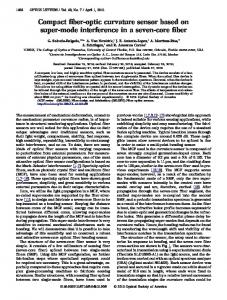
2.1. Structure and output spectral response The all-fiber structure is shown in Fig. 1. A piece of endlessly single-mode PCF (ESM-12-01) is spliced between a lead-in and a lead-out SMF-28 fiber. The PCF fiber section is stripped off from the polymer coating, so that the outer refractive index is that of air. In such a structure, higher-order cladding modes of the PCF fiber, which would otherwise be radiated through the polymer cladding, are now guided, the surrounding medium (air) acting as a low-refractive-index cladding. Abrupt taper LP01
SMF-28
Air
Spatial filter
LP01(core) LP0p (cladding)
ESM PCF Splices
LP01 SMF-28
Fig. 1 Schematic representation of the core-cladding intermodal interferometer based on the mode-field mismatch method. The abrupt tapers are formed at the splices between two dissimilar fibers such as the standard SMF-28 and the endlessly single-mode PCF.
Looking at the data in Table 1, we notice that the diameter of the fundamental LP01 mode in the SMF-28 fiber is wSMF = 9.2 µm whereas in the PCF wPCF = 6.4 µm. We thus obtain an abrupt change of the waveguide properties,
65
Optical Power, P , (dBm)
which means that at the splice we have an abrupt taper. Also, as shown in [2], the fundamental mode field coming out of the SMF will broaden due to diffraction in the region of collapsed holes. For this reason, the LP01 mode distribution of the SMF-28 fiber cannot adapt smoothly to the LP01 mode distribution of the PCF fiber and couples part of its power to higher-order cladding modes of the PCF fiber. Normally, if the PCF fiber is polymer-coated these modes will exhibit high loss. If the PCF section is stripped, however, these cladding modes are better guided and their fields overlap with the field of the fundamental LP01 coremode. We then will observe interference between a core and a cladding mode. At the second splice we have another abrupt taper and the SMF-28 lead-out fiber does not support the higher-order cladding mode. Whatever cladding modes are excited get quickly attenuated, so the second SMF-28 fiber section acts as a spatial filter for the intermodal interference pattern. We thus have an all-fiber core-cladding intermodal interferometer in an in-line Mach-Zender arrangement.
ESM-12-01-PCF
Mode field diameter
9.2 ± 0.4
6.4 ± 0.2
8.2
12.0 ± 0.1
125 ± 1
125 ± 1
N.A.
57.4 ± 1
Core diameter Cladding diameter Holey region diameter
Epoxy
SMF-PCF-SMF
mm
0
Ls = 33.5 mm
-2 -4 -6 y = -60,801x + 0,0418
-8
R2 = 0,9997
-10 0
0,05 0,1 0,15 Absolute elongation, ! l (m m )
Wavelength shift, !" (nm)
(a) Minimum wavelength shift under elongation
SMF
LS
1610
1565
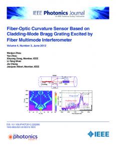
2.2. Experiment and results Fig. 2 shows the dimensions of the sensor arrangement for strain sensing. Because of the epoxy area covering the splices, the active sensing length is reduced from 44 mm to Ls = 33.5 mm. We measured the wavelength shift at 1604 nm from Fig. 3 caused by elongation and the results are plotted in Fig. 4(a). Similarly to LPGs, the sensitivity to strain has a negative coefficient, which means that the interference pattern moves left to lower wavelengths and for the sensing length of Ls = 33.5 mm the sensitivity was found to be dλ/dl = -60.801 nm/mm.
L PCF
−46 1520
Fig. 3 Spectral response of an intermodal sensor
There are two important features of the present LP01LP0p interferometer compared to core-core intermodal interferometers. The first is that it shows very low temperature sensitivity since the PCF fiber is made of a single material. The second is that, since one of the interfering modes is a cladding higher-order mode, its effective refractive index, and consequently its propagation constant, will be very sensitive to the refractive index of the surrounding medium. We fabricated several samples of all-fiber SMF-PCFSMF structures as shown in Fig. 2, establishing lengths of the PCF section from L = 5 mm to L = 53 mm. The sample having the PCF section with L = 44 mm was subjected to different tests.
SMF
−36
Wavelength shift, "# (nm)
SMF-28
−26
Wavelength λ (nm)
Table 1. Parameters of the SMF-28 fiber and the ESM-12-01-PCF Parameter [µm]
SMF-PCF-SMF
−16
Epoxy
SMF-PCF-SMF
0,15
Ls = 45 mm
0,1 0,05 0 -0,05
y = 0,003x - 0,0772 R 2 = 0,2799
-0,1 -0,15 0
Fig. 2 Structure of the sensor
20 40 Tem perature, T (C)
60
(b) Temperature effect
Using an ASE broadband source and an Ando AQ6315A OSA, the spectral response of the intermodal sensor was taken and the periodic structure is shown in Fig. 3.
Fig. 4 Response to elongation
Measurement of temperature sensitivity was performed on a third sensor with Ls = 45 mm. The wavelength shift of
66
its first minimum is shown in Fig. 4(b). The sensitivity to temperature was found to be in the order of dλ /dT = 3 pm/K. The sensitivity to pressure was measured after we installed another sensor with length Ls = 40 mm in a highpressure chamber. The wavelength shifts vs. pressure are shown in Fig. 5(a) and the sensitivity was found to be dλ/dp =16.9 pm/bar. During pressure changes, the spectrum of the sensor moved to higher wavelengths and also changed shape as can be seen from Fig. 5(b).
Intensity, I (arb. units)
4
SMF-PCF-SMF Ls = 40 mm
4
Wavelength shift, !" , (nm)
transition air-water has been evaluated. Fig. 6 shows a comparison of the spectral responses in air (n =1) and in water (n = 1.3352) for an interferometer whose length is L = 50 mm.
3
1
0
50 100 150 Pressure, p (bar)
1550 1560 1570 Wavelength, ! (nm )
1580
1590
The two responses in water correspond to sensing lengths of Ls = 10 mm and Ls = 33 mm. For the 33 mm sensing length, the wavelength shift was δλ = 5 nm per refractive index change of δn = 1.3352-1 = 0.3352 r.i.u (refractive index units). Since the 2π spectral period is Δλ2π = 18.2 nm, then we can find that Tn = 1.22 r.i.u. and the corresponding sensitivity is Λn = 5.14 rad/r.i.u. The TnxLs product can then be calculated as 4.03 x 10⁻³ r.i.u.x m. In the refractive index range from 133 to 1.38, Tn = 0.18 r.i.u. (Λn = 34.88 rad/r.i.u.) and in the range from 1.38 to 1.46 , Tn = 0.027 r.i.u. (Λn = 230 rad/r.i.u.) as summarized in Table 2. Thus, as with LPGs, sensitivity dramatically increases as the external refractive index approaches that of the cladding. It is worth comparing the present sensor with conventional SMF-28-based LP01-LP02 intermodal sensors as well as with PCF-based LPGs. Table 2 compares the present PCF-based core-cladding mode interference sensor and an earlier SMF-28-based corecore mode interference sensor. The sensitivity is expressed in terms of the Tξ x Ls product which is a constant quantity. We see that this PCF intermodal sensor is about 40 times less sensitive to temperature (which is important for temperature compensation), 9.3 times less sensitive to strain and about 5.8 times more sensitive to pressure.
200
(a) Minimum wavelength shift under pressure
30
1540
Fig. 6 Spectral response to external refractive index
0
Optical Power, P (µ W)
2
1
40
Air H2O (10mm) H2O (33 mm)
3
0 1530
y = 0,0169x - 0,1926 R2 = 0,9882
2
SMF-PCF-SMF
SMF-PCF-SMF
Ls = 40 mm
0 bars 180 bars
20 10 0 1520 1540 1560 1580 1600 1620 Wavelength, ! (nm )
(b) Spectrum response to pressure Fig. 5 Response to hydrostatic pressure
As is also evident from Fig. 5, the different minima shift to different wavelengths. There are two reasons for this. The first is the presence of more than one higher-order cladding mode excited at the splice, which leads to multiple instances of intermodal interference. This problem can be eliminated by placing the cladding in an immersion liquid with a suitable refractive index or, if this is inappropriate, by etching part of the cladding to increase the spacing between the higher-order modes. The second reason for the shift to different wavelengths is the existence of polarization dependence of the intermodal interference. This polarization sensitivity arises in the collapsed regions at the splices where the holes of the PCF fiber become elliptic in shape with random orientation, which, in turn causes random parasitic birefringence. Since the higher-order mode is a cladding mode of a glass-air waveguide, any change of the outer refractive index caused by immersion in a liquid will change the propagation constant of the higher-order mode and consequently cause a shift in the interference fringes. Given that the sensors have to be inserted into a liquid for pressure measurements, the sensitivity to refractive index for the
Table 2. Comparison of responses between the present LP01-LP0p PCF-based interferometer and a previous LP01-LP02 SMF-based intermodal interferometer. Parameter Temperature Strain Pressure Refractive index
67
Tξ x Ls product TT xLs (Kxm) Tε (µε) TpxLs (bar x m) TnxLs (r.i.u.x m) (Ls =33 mm)
LP01-LP0p PCF-based 305.87
LP01-LP02 SMF-based 7.75
9 850.8 32.9
1 058 190
4.03.10-3 (n = 1.00 to 1.33) 5.94.10-3 (n = 1.33 to 1.38) 8.91.10-4 (n = 1.38 to 1.46)
----
Table 3 compares the same PCF-based core-cladding mode interference sensor and a PCF-based tapered LPG (TLPG) reported in [8]. The TLPG’s sensing length is Ls =40 mm, while the lengths of the PCF core-cladding intermodal sensor vary between 33 mm and 45 mm as indicated in parentheses.
changes as well as to bending. It shows a 5 times greater sensitivity to pressure than a core-core intermodal sensor based on SMF-28 fiber and 50% higher sensitivity than a tapered PCF-based LPG. As the sensing fiber is a photonic crystal one, temperature sensitivity is very low. This type of sensor features the typical advantages of PCF-based LPGs but its sensitivity can be increased by increasing the sensor length.
Table 3. Comparison of responses between the present LP01-LP0p PCF-based interferometer and PCF -based tapered LPGs.
ACKNOWLEDGMENTS
Parameter
d λ/dχ
Temperature
d λ/dT (pm/K)
Strain
d λ/dl (pm/µε)
Pressure Refractive index
d λ/dp (pm/bar) d λ/dn (nm/r.i.u) (Ls =33 mm)
LP01-LP0p PCF-based