Novel Immune-based Framework for Securing Ad hoc Networks Yasir Abdelgadir Mohamed
Azween B. Abdullah
Department of Computer and Information Sciences Universiti Teknologi PETRONAS, Bandar Seri Iskandar, 31750 Tronoh, MALAYSIA +6053687423 +6053687507
[email protected]
ABSTRACT One of the main security issues in mobile ad hoc networks (MANETs) is a malicious node that can falsify a route advertisement, overwhelm traffic without forwarding it, help to forward corrupted data and inject false or uncompleted information, and many other security problems. Mapping immune system mechanisms to networking security is the main objective of this paper which may significantly contribute in securing MANETs. In a step for providing secured and reliable broadband services, formal specification logic along with a novel immuneinspired security framework (I2MANETs) are introduced. The different immune components are synchronized with the framework through an agent that has the ability to replicate, monitor, detect, classify, and block/isolate the corrupted packets and/or nodes in a federated domain. The framework functions as the Human Immune System in first response, second response, adaptability, distributability, and survivability and other immune features and properties. Interoperability with different routing protocols is considered. The framework has been implemented in a real environment. Desired and achieved results are presented.
Keywords Security, MANETs, specification logic, mobile agent
1. INTRODUCTION Confidentiality has become the most important factor that determines interaction among people as well as network devices. The users’ fears arise from the wireless features of mobility and loosely connected infrastructure. In mobile ad hoc networks (MANETs), nodes are free to move as they wish, thus the network topology may change in an unpredictable way at unpredictable times. The wireless channels in mobile ad hoc networks have a broadcast nature with two consequences [1]: unless security is enforced with external mechanisms, communication remains insecure. Secondly, a high collision possibility is expected due to overhearing caused by the nodes in the transmitter communication range, and the contention of the shared medium, therefore, decreasing the bandwidth. Furthermore, the malicious node Permission to make digital or hard copies of all or part of this work for personal or classroom use is granted without fee provided that copies are not made or distributed for profit or commercial advantage and that copies bear this notice and the full citation on the first page. To copy otherwise, or republish, to post on servers or to redistribute to lists, requires prior specific permission and/or a fee. SAC’10, March 22-26, 2010, Sierre, Switzerland Copyright 2010 ACM 978-1-60558-638-0/10/03…$10.00
[email protected]
could introduce serious disruptions into the whole hybrid network. The decentralized nature of network control in MANETs makes them more prone to physical security attacks; hence, solutions should follow the same nature and must be distributed as each node at any time could set off the communication range of any other node. On the other hand, the immune system has many features that are desirable for the imperfect, uncontrolled, and open environment in which most computers currently exist. These include distributability, diversity, disposability, adaptability, autonomy, dynamic convergence, anomaly detection, multiple security layers, identification via behavior, no trusted components, and imperfect detection [2]. A wide variety of architectures for the computer immune system have been inspired from the foregoing features. In this research we are trying to emphasize more immune features, components, and processes that can help to contribute to one of the important areas; MANETs security The rest of this paper is organized as follows: The related works are highlighted in section 2, while the framework upon which the specification is based is depicted in section 3, the logic is specified in section 4 followed by the conclusion and the future work.
2. BACKGROUND AND METHODOLOGY In [3], a mechanism for detecting unauthorized and compromised nodes in a mobile ad hoc network has been proposed. The detection procedure depends on two phases. In the first phase, an authentication mechanism to determine the node’s identity takes place through using one of the authentication protocols. Phase two depends on an agent that is embedded into all nodes, knows the user’s standard profile, records deviations, gathers and analyzes and audits data locally, and passes a confidence interval to the neighbor. In [4], a bio-inspired self-organized secure autonomous routing protocol has been proposed for securing wireless sensor networks. The goal is to minimize the initial broadcasting process to save the battery life time. It has been cited that the security enhancement is based on the human nerve barrier system in order to differentiate between a good and malicious node to decide whether it can join the domain or not. The routing mechanism is designed to use some metrics to make security decisions. This work is a proposal and no actual implementation or simulation experiments have been done. In [5], a hybrid model for network intrusion detection has been presented .The Network Threat Recognition with Immune Inspired Anomaly Detection, or NetTRIIAD, model is divided into an Innate Layer and an Adaptive Layer. Two features are included in the NetTRIIAD antigen: address features (32 bits) and
protocol features (32 bits). The features are derived from IPv4, TCP, and UDP protocols. The danger model signal in NetTRIIAD includes two elements: single feature value and signal level value. In [6], a previous work on mobile ad hoc networks has been extended [7], [8] [9]. The sequences of protocol events are collected in two positions: at the nodes belonging to the route where the packet loss is observed, and during the time close to the packet loss time. Accordingly, they are considered as non-self antigens. Both negative selection and danger theory mechanisms are used to affirm the non-self detection. The system has the potential to be disposable, distributed, self-organized and lightweight, but has not been demonstrated in a realistic ad-hoc network yet.
3. SECURITY FRAMEWORK 3.1 Overview The work in progress is a continuation of what has been done earlier. The four mobile agents’ method had been proposed to secure the ad hoc domain [10]. Due to scalability and bandwidth constraints in ad hoc networks [11], the approach has been revised into a new one that proposed one agent with many roles and functions to secure the ad hoc domain [12]. In the following subsections, more progressive steps on the same concept have been derived.
A IA activation Updates Completion
Screening (Monitoring / Detection)
B Security role
Figure 1. CPN model for main IA processes The configuration process, which is the initial phase that leads up to the activation state, will be carried out in two phases; the first phase is in a secured environment which is a secured configuration phase while the second is an application phase. In the first phase, the IA is configured to monitor the traffic in a domain with no internet connection, which is an error free and secured environment. The network set-up sequence structure is depicted in Figure 2 below.
3.2 Framework As stated earlier and to synchronize the different immune processes, an agent with different roles and functions that maps different components, processes, and tasks has been introduced. The different studies have proved that the success in mapping more immune processes and features results in a robust security system for the concerned application [13]. In Table 1, some of the immune features have been mapped to the security protocol. This mapping is highlighted in the next section. Table 1. Mapping immune system to the security framework Immunity Body B-cells T-cells Lymphocytes Memory Cells Negative Selection Clonal selection Hyper mutation mask Self/ non-self Danger theory Tolerisation Self-healing Distributability Adaptability APC(Antigen Presenting Cell )
Ad hoc network Domain Ad hoc Domain Immune Agent (IA) Detectors Nodes Database inside the IA Match-delete process (secure environment) High scored detectors Detectors cover Frequently occurred/ abnormal pattern Observation effects of non-classified pattern Inmatchability with the self patterns Recovery process part Distributed IA copies Updated database in the IA The scanning process where the detectors can successfully disclose the non-self
The Main activities carried out by the Immune Agent (IA) to perform the security task can be identified in the following coloured Petri net (CPN) states and transitions illustrated in Figure 1.
Figure 2. Network setup sequence structure During the secured configuration phase that will be conducted offline with no internet connection, three profiles will be created; self patterns, non-self, and detectors profiles. These profiles represent the basic database located in the IA, updated during the application phase and then distributed later to all copies inside the domain. The designation of the three profiles can be summarized as follows: • Self patterns’ profile. All the protocol header events must be represented in binary strings that have a length of l and are considered as a self pattern ε ∈ Sf (acceptable events). These strings are analogous to peptides in the immune system. To build the self patterns profile (GenesProfile), we aim to divide the protocol header into sub patterns, each of which is 8 bits in length that has been selected to control negative and positive faults. The self patterns can be represented as Sf = {sf1, sf2 ..,sfn }. • Detectors’ profile. Based on the self patterns, the detectors’ profile is created. In our research, a random function generator is used. Each detector is then compared to the entire self patterns in the self profile; each has the same length as the self. The ones that match any of the existing self patterns will be discarded while the others are stored in the detectors profile. This is called the negative selection
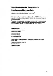
algorithm (NSA) [14], [15]. The appropriate matching rule for the matching probability is driven from [16]; the matching probability (Pm) for 8-bits detector length is depicted in Figure 3. The Pm equation can be written in the following form where (L) is the detector length while (r) is the threshold for the matching bits: Pm = 2-r ((l -r)/2+1
Request for establishment
Routing protocol adaptation
connection
IA configuration
Controlled less secured environment
Secured environment (TRAINING) Frequently and necessary patterns and events for connection establishment
Infrequent patterns Detectors Profile
Profiles
Negative selection test
Cloned detectors (TRAINING) IA Encapsulation
Application phase (node side) PSC (periodic system check) Profiles updates
Send IA to application phase
Monitoring/Detection Blocking/isolation
Recover
Figure 4. Immune Inspired Security Architecture
Negative selection test
•
Figure 3. Matching probability As depicted in the figure, as long as the threshold (matching bits) approaches the detector length value, the matching probability becomes high. Evidently, the detector’s length directly affects the detection process. A self pattern might be caught as malicious while a non-self might be treated as good; this is considered as false positive and false negative respectively, which can be reduced by controlling the detection threshold. Non-self patterns’ profile: Using the generated detectors, a classification to the incoming patterns could be achieved. Since the detectors are generated and trained not to match the self, the matching is expected to come about when nonself patterns are encountered, Nf = {nf1, nf2… nfm,}.
In Figure 4, the different components for the security framework are illustrated. In wireless ad hoc networks the connection establishment depends on the protocol according to which our security protocol is activated. The routing protocol adaptation box in the figure will be explained later in this paper. Following the protocol adaptation, the IA will be configured. The configuration process includes the following: • IA will be configured to create the abovementioned profiles and perfectly trained to update them. • IA remains valid as long as the node remains within the domain, otherwise and according to the privilege, the node might be requested to apply for another IA to rejoin the domain again. • To maintain the survivability, a part of a self- healing process will be performed, where possible to recover the corrupted nodes. IA store the necessary data recovery file to recover the infected nodes. • Depending on the pattern/node classification, a block/isolation, node recovery, or permission for a normal communication will be decided. Soon after the IA gets configured, the training phase in a secured environment starts. The three basic profiles (self, non-self, and detectors) will be created where the negative selection algorithm plays the significant role in validating the detectors’ profile. The profiles are then sent to the next phase where a less secure -but controlled- environment is deployed. The less secure environment here is needed to train the detectors to deal with the shapes of different attacks. Detectors’ production and training are similar to that which takes place in the bone marrow and thymus respectively in the immune system. Clonal selection (Figure 4) is one more immune mechanism that plays an important role in this phase. It is complementary to the role of negative selection. It explains how an immune response is mounted when a non-self antigenic pattern is recognized by a specific type of cell labeled as B-cell [16].
The B-cell proliferates when its receptors bind to pathogens scoring high affinity. The same concept is mapped to our framework by setting a score for the detectors; a detector will be cloned when it attains the score in detecting a certain number of non-self. Since the detector length in our work is set to 8-bits, the maximum tries number to clone a valid detector may not exceed the value depicted in equation (2) where n is the detector’s length, and M is the maximum tries to generate a valid cloned detector. The relation between M and n is illustrated in Figure 5. (2) M = 2n log2 2
hoc networks, a standard mechanism has to be set to generalize this framework to all routing protocols. As illustrated in Figure 6 and as a description to the protocol adaptation part which appeared in Figure 4, the routing protocol will be examined to determine whether a reactive protocol or a reactive it is. Communication Protocols database
Maximum tries
Not recognized
Check routing protocol code
Reactive
Learning process
Proactiv
Detector’s length
Use the routing table
Use the RRP
Figure 5. Maximum tries to generate a cloned valid detector Such a type of calculation is necessary to consider the space and time complexity for the inspired algorithms. The diagram affirms that the space complexity in a worst case is not linear to the number of bits in the detector length. When the IA is perfectly configured and equipped with the different profiles, it will then be encapsulated and sent to the destination using the routing protocol packets. The next step is the application phase where an IA performs the security task. After the IA gets attached to the guest platform (destination node), it initially stores data recovery files in the agent’s local database and then monitors the incoming packets. The different profiles in the local database help to classify the incoming patterns, consequently a decision on how to treat the patterns will be made. The normal patterns will be permitted while the abnormal will be ignored/ blocked.
3.3 Mapping the danger theory mechanism The detection probability becomes high because of the detector’s length, therefore, the false positive and false negative is expected to rate high as well. To reduce blocking the self patterns or allow the non-self patterns, the IA is configured to check the node’s system periodically during the communication process and to observe the effects of the incoming patterns of strings. The patterns that have negative effects will be blocked while the ones with positive effects will be received as usual. This concept has been derived from the danger theory concept of the immune system. It has a significant role in protecting the body against different attacks [17, 18]. There still remain the patterns that are not classified (neither self nor non-self) which will be classified as suspect patterns, and reclassified after the periodic system check results. The output of the application phase will be the updates for the different profiles needed for securing the domain. These updates will be multicasted to all IA copies inside the domain for an improved performance in the future.
3.4 Routing protocol adaptation Our immune security framework depends on the routing protocol deployed to establish the connection between the sender and the receiver. Since there are many routing protocols in the wireless ad
Packet routing
Figure 6. Routing protocol adaptation In the first case where the routing on demand technique is deployed, the IA uses the route request packet (RRP) to be encapsulated in. In the second case where routing tables are deployed, a copy of the routing table should be stored in the agent’s local database. According to the packet handling mechanism in the chosen routing protocol, the IA is then encapsulated. In the cases of the new unknown routing protocols, a learning process is deployed to record the new protocol in the local database. The new routing protocol entry in the database will be broadcasted to the rest of the IAs inside the domain for ease of future usage.
3.5 Security framework specification As a first step towards the security protocol implementation, specification logic for the security framework is described in this section. Definitions are given as needed to understand the different terms that being used. Definition1. A federated domain is a set of collaborative trusted wireless nodes existing in a limited region offering a secured communication that follows the same security license. ƒ= < χ, γ, Ђ > where as χ is a set of nodes in a domain = {x1, x2…xn}, γ is the license upon which a node is accepted to join the federated domain, Ђ is the immune agent that is used as the security license tool Definition2. A security license is a set of rules the different parties should follow to get the benefits of the services provided by these parties. According to the license acceptance there will be two types of nodes: • IA holder: A node that holds an IA, which can use the agent for limited security purposes but has no authority to distribute it to any other node. The agent is configured to be terminating soon after the node leaves the federated domain.
•
IA distributor: In contrast to the holder, the distributor has the authority to establish a new federated domain using its own license in case it leaves the federated domain. A node (xi) could be in one of four scenarios: I. A new node (xi) that intends to join a federated domain xi→ χ (Ђ) to be either a holder or a distributor according to the conditions that it accepts the license. II. A node (xi) intends to leave the federated domain χ (Ђ) \ xi. III. A distributor node that leaves a federated domain and wants to establish a new domain. IV. A node xi in a federated domain needs to communicate with a node in another federated domain: xn (Ђ) i↔ xn (Ђ) j. The four scenarios can be demonstrated in Figure 7 below.
(II)
(Ђ) /
χi (Ђ)
ƒ
(I)
λ
Checking process
U
Set of all patterns (self + nonself)
⇎
Connection terminated
χ
Nodes inside a domain
ψ
Detectors set
ω
Monitoring phase activation
sf
Self patterns
⇻
Save process
⇹
Match process
γ
Immune agent license
DrP
Detector Profile
CS
Connection establishment
⇶
Broadcast process
RVR, BLCK Recover and block processes 1. Configure Immune Agent (IA): Training phase: IA := < Sf , Nf , DrP, δ, RVR, BLCK>
(IV) χj (Ђ)
(III)
ƒ Figure7. Different scenarios for the federated domains Before the specification logic being explained, the different notations used in the logic are clarified in Table 2. Table 2. Notations Symbol
Description
β
System components
Ω
Classification process
δ
Detector
ε
A change in system
↺
Connection between two in a secure environment
η
Run periodic system check
SP
Temporary file: suspect patterns file
τ
A pattern
↹
Block process (BLCK)
Ю
Recovery process (REV)
Φ
IA deactivation
PCKs
packets
ρ
Clone process
(Immune Agent configured with the necessary components; self, non-self, and detectors profiles, detection, recovery, and blocking functions) 1.1 Building self/non-self profiles: S/N prf ::= < PCKs,χi ,εi > IA:ω PCKs ‖ χi ↺χj (IA monitors the packets within a traffic between two nodes, no internet) IA: εi ⇻ {Sf} ‖ ε: = l: [a0 a1 …an], ai= {0, 1}, i= {1, 2, 3…n}; (Save the frequently occurring patterns as self patterns, each pattern has the fixed length l and consists of a string of Boolean) IA: εi ∉ {Sf} ⇻ {Nf} 1.2 Building detectors profile (DrP): DrP::= BRG (PCK,δ) = l : [b0 b1 b2…bm] ‖ bj= {0, 1} (Applying a function for randomly generating detectors with length l) ∀δi: ⇹ εi; if δi = εi delete; else δi⇻ψ:= {δ0, δ1... δn} (Each generated detector matched with the entire self patterns, either deleted or saved, negative selection test) IA: ρ = F (ψ) (Pass the detectors profile to clone function) ρ : ω PCKs‖ χi ⇆χj (Clone process run in a live environment) ρ : ∀δi: δi (score=0); (For each detector, set a score for matching the non-self patterns) ρ : δi⇹nf ‖ nf∊ {Nf} ∴δi (score++) (If a detector matches a non-self; increase the score for the detector) ρ : δi (score)≥ Threshold ∴ρ(δi)= δi∗ (Pass the high scored detectors to clone function to generate new detectors from the high scored one)
2.
3.
ρ : δi∗⇹εi ‖∊ {Sf} ∴ delete; else δi⇻ψ (Apply the negative selection test to the new detector, and then update the detectors profile) Connection establishment (CS): CS::= CS:χi+1 ⇾ RRP (Node χi+1 sends route request packet to find a path) CS: ∀ χ ∃ χi (IA) (In the domain there exists a node, in which, the IA is installed) CS: χi ⇽ (REP+ γ) (Responds with route path and a license of accepting IA) CS: χi+1 ⇺ (γ) (Accepts license) CS: χi (DA, SA, UI, IA) ⇾ χi+1 (Reply (destination address, source node address, unique identification number, and the IA) Securing Node χi+1: IA: ⇿χi+1(t) (Perfectly connect to the node’s system at time t) IA: ⇻DRF (t) (Save a copy of the Data Recovery File at time t (before data transfer)) IA: ω PCKs (Activate the monitoring phase) IA: Ω PCKs/τ (Classify the incoming patterns) IA: ∀τi ⇹sfi ‖ i = {1, 2, 3…n} (Match with self patterns) τi :τi ∊ {sf}? ⇹ PCKs (Match? Permit packets transfer) 3.1 Periodic system checker: PSC (η) ::= τi :τi ∉ {sf} then η (Run Periodic System Check (PSC)) τi :τi ⇻ {Sp} (Save a pattern in the temporary file, queue for classification process) η : Let βt= {β1, β2… βn} (Represents the system components; danger theory part) η : IAη β(t) (Periodic system check components at time t) η : IA η βˆt+∆t
(Repeat the check at time t+∆t) η: βt = βˆt+∆t; τi ⇻ Sf
(No negative effects of the pattern τi, (save τi to the self profile) η: βt = β(t+∆t) (System harmed) 3.2 Blocking process (BLCK): BLCK ::< τi, Nf , χ, count--> IA ↹ τi (τi blocked gradually) IA (χi+1): ⇶ τi ∀ χIA (IA in nodeχi+1 will broadcast the new pattern(s) to all IAs inside the domain) IA: ∀ (χi+1) ∊ χ ⇻ Nf
(Node χi+1 update the non-self profile by adding the new pattern(s)) IA: IA count-IA: IAΦ: Count=0, or χi+1 ⇎ χi (IA deactivated in case of connection terminated or agent counter = 0) 3.3 Recovery process REV (Ю)::= < η, DRF, β(t) > IAη β(t) IA: (System check) IA: λ (DRF); if exist ∴Ю else ↹ (Check the data recovery file for recovering missing files, if exists; recover, else call block process)
4. RESULTS AND DISCUSSION This work has been implemented in a wireless environment that contains one mobile node and two stationary nodes connected through an access point and wireless adapters. For the prototyping purpose, the protocol used was IEEE 802.11g and the operating system was windows XP. The code is written in JAVA and MYSQL-front and MYSQL Command Line Client were used for the output. In the offline (secured) phase where the domain is isolated from other networks (including internet), self-profile and detectors-profile have been created. A sample of the captured patterns table is shown in Table 3. Table 3. Sample of incoming patterns profile PATTERN_ID 1 2 3 4 5 6 7 8 9
PATTERN fa9cf 16f8cd0 1bd4722 1b10d42 aa9835 e80a59 1c672d0 1050169 7a84e4
TYPE GE SU SU GE GE SU SU SU SD
URL 192.168.1.3 192.168.1.3 192.168.1.3 192.168.1.5 192.168.1.3 192.168.1.8 192.168.1.8 192.168.1.8 192.168.1.8
10
e3b895
SF
192.168.1.5
The incoming patterns profile contains the following types of patterns: •
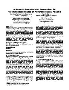
Self patterns (SF): Incoming patterns that do not match with detectors hence classified as self patterns. • Genes patterns (GE): Incoming patterns that match with the frequently occurring patterns that are captured and stored as pure self. • Self patterns from cloned detectors (SD): Patterns that are classified using the cloned detectors. • Nonself patterns (NS): the patterns other than the genes (GE) and detectors are classified as nonself if it affect the NTFS files. • Suspect patterns (SU): The incoming pattern is firstly classified as suspect (SU) and then all the NTFS files in the C drive are checked to verify that no alteration had been by the suspect patterns. During the test period it has been found that the count for genes patterns (GE), self from detectors (SD) patterns, self patterns, suspect patterns, and nonself patterns were 32283, 6821, 954412, 111795, and 5518 respectively. The five data types are shown in
Figure 8. In the same figure thee generated deteectors used in thhe F c classification beesides the high h scored detecctors cloned are a d depicted.
1000000 900000 800000 700000 600000 500000 400000 300000 200000 100000 0
system files, it is then considered as a self as shown inn Figure 11. p initiallyy classified as suspect, but theeir behavior Some patterns indicatee that it is not malicious m and heence they are recclassified as self.
Figure 11. A suspect pattern n reclassified ass a self The coorrupt patterns that t harm the NTSF N files are classified c as nonselff and it will bee blocked. The time at which damage d has been chhecked is declareed at pattern_dam mage_node_tim me column in the in Figure 12. As A an example, pattern fcfc677 has been encounntered as nonsellf with three diffferent pattern_iid incoming from thhree different noodes. A search in the block_paatterns table shows that t the same paattern is then blocked.
Figure 8. Incoming patteerns and detectoors profiles The patterns are firstly classifieed as a suspect and shown in thhe T s screen shot in Figure 9. After A a change,, alteration or a m modification to one of the NTFS files in the system for thrree c counts it is then reclassified r as no onself.
F Figure 9. Patterrn reclassificatioon As depicted in thhe figure, regard A dless of source address, the sam me inncoming patternn will be captureed, e.g. pattern 17a29a1 1 had been c classified during the first three co ounts as a suspect pattern wheree it h been assigned id 43437 seent from 160.0.53.202, the sam has me p pattern is captureed again with diffferent id 1715099 as a nonself seent fr from 160.0.53.200 when a chang ge in one of thee system files has h b been discovered. The pattern thaat is classified ass a nonself will be b b broadcasted to thhe rest of the nod des so as to be treated t properly as a nonself in futture. Figure 10 depicts that thee same pattern is c classified by diffferent nodes as a nonself.
Figure 10. A pattern F p gets sa ame classificattion by different n nodes T entire incom The ming patterns thaat have not beenn classified will be b s stored as suspectt patterns (SU). If it has been encountered e moore thhan three timess and at the sam me time it doeesn’t affect NTF FS
Figure 12. Blocked B (MNB) nonself pattern ns In Figuure 12, pattern fccfc67 had been sent from differrent sources, howeveer, since it wass classified as nonself by onee node, the classifiication was broaadcasted to all doomain and the same s pattern is then blocked. Since the application phase was condducted in the domainn after connectinng to the internnet, the only bloocked nodes were thhe ones that exisst inside the dom main. Some maliicious nodes send malicious m patternns through the gateway whichh cannot be blockedd; otherwise thiss would block thhe internet. The source node that keeeps sending malicious will be bllocked as depicted in Figure 13.
Figure 13. Malicious node n blocked
5. CONCLUSION AND FUTURE WORK The success in mapping immune features and properties depicted in Table 1 above is expected to contribute to the ad hoc security field with a new auto anomaly detection mechanism, memory mechanism for better future reaction, self isolation for the malicious nodes resulting in a trusty communication environment, and nodes’ survivability. The immune-based security framework for MANETs has been presented. An intelligent agent that contains three profiles, self cells profile, non-self profile, and detectors’ profile is created. Replicas of the agent are distributed to all nodes inside the domain upon connection. A combination of negative selection, clonal selection, and danger theory mechanisms have been mapped for a self-organized system. The framework resolves some limitations which appeared in the previous works including our prior model. The major well thought-out issues are scalability and the bandwidth conservation, which mainly characterize the ad hoc networks. The work was implemented in static environment and the mobility so far has not been tested and will be conducted in a simulation experiments later. We plan, as a future work, to generalize this protocol by applying it to an application domain that has more nodes and much complicated scenarios as a verification.
REFERENCES [1] Bowman, B., Debray, S. K., and Peterson, L. L. Reasoning about naming systems. ACM Trans. Program. Lang. Syst., 15, 5 (Nov. 1993), 795-825. [2] Ding, W., and Marchionini, G. A Study on Video Browsing Strategies. Technical Report UMIACS-TR-97-40, University of Maryland, College Park, MD, 1997. [3] Nikos Kominos, Dimitris Vergados, and Christos Douligeris, “Detecting Unauthorized and Compromised nodes in mobile Ad hoc networks”, Elsevier, 2007, pp. 289-298. [4] Kashif Saleem, Norsheila Fisal, “Bio-Inspired Self-organized Secure Autonomous Routing Protocol for WSN”, international RF and Microwave conference proceedings, 2009, pp. 417-421. [5] Robert L. Fanelli, “A Hybrid Model for Immune Inspired Network Intrusion Detection”, Springer journal, 2008, pp. 107–118. [6] Le Boudec,,J.,and Sarafijanovic, S. An artificial immune system approach to misbehavior detection in mobile ad-hoc networks. Technical Report IC/2003/59, Ecole Polytechnique Federale de Lausanne, 2003. [7] Le Boudec, J.and Sarafijanovic, S. An artificial immune system approach to misbehavior detection in mobile ad-hoc networks. In Proceedings of Bio-ADIT 2004 (The First International Workshop on Biologically Inspired Approaches to Advanced Information Technology), pages 96-111, Lausanne, Switzerland, January 2004.
[8] Sarafijanovic, S. and Le Boudec, J. An artificial immune system approach with secondary response for misbehavior detection in mobile ad-hoc networks. Technical Report IC/2003/65, Ecole Polytechnique Federale de Lausanne, 2003. [9] Sarafijanovic, S. and. Le Boudec, J An artificial immune system for misbehavior detection in mobile ad-hoc networks with virtual thymus, clustering, danger signal and memory detectors. In Proceedings of the 3rd International Conference on Artificial Immune Systems (ICARIS'-04), pages 342- 356, Catania, Italy, September 2004. [10] Mohamed, Y.and Abdullah, A. Security Mechanism for MANETs, Journal of Engineering and Science Technology, , 2008 pp. 231-242. [11] Tommy Chu and Ioanis Nikolaidis, “On the Interaction of Bandwidth Constraints and Energy Efficiency in All-Wireless Networks”, Springer, LNCS 2865, 2003, pp. 211–222. [12] Mohamed, Y, and Abdullah, A. “Immune Inspired Approach for Securing Wireless Ad hoc Networks”, International Journal of Computer Science and Security(IJCSNS), vol 9, No 7, pp 206-212. [13] De Castro, L. N. and Von Zuben, F. J. (1999).“Artificial immune systems: Part I basic theoryand applications”. Tech. Rep. RT DCA 01/99“Artificial immune systems: Part I basic theoryand applications”. Tech. Rep. RT DCA 01/99. [14] Forrest, S. Perelson, A.S Allen, L. and Cherukuri, R. “Selfnonself discrimination in a computer”. In the proceedings ofthe 1994 IEEE Symposium on Research in Security andPrivacy, IEEE Computer Society Press. 1994. [15] Sankalp Balachandran, Dipankar Dasgupta, Fernando Nino, Deon Garrett, “A Framework for Evolving Multi-Shaped Detectors in Negative Selection”, IEEE Symposium on Foundations of Computational Intelligence , 2007, pp. 1-8. [16] Steven A. Hofmeyr. "An immunological model of distributed detection and its application to computer security", PhD thesis, University of New Mexico, Albuquerque, NM. (1999). [17] D'haeseleer, P. Forrest, S and Helman, P. An immunological approach to change detection: algorithms, analysis and implications. In the Proceedings of IEEE Symposium on Security and Privacy, pp. 110 - 119. June, 1996. [18] Aickelin U., Bentley P., Cayzer S., Kim J. and McLeod J. (2003). “Danger Theory: The Link between AIS and IDS?” In Proceedings ICARIS-2003, 2nd International Conference on Artificial Immune Systems, LNCS 2787 147-155.