Combined Radial-Axial Magnetic Bearing for a 1 kW, 500,000 rpm Permanent Magnet Machine P. Imoberdorf, C. Zwyssig, S. D. Round and J.W. Kolar
Abstract – Ultra-high-speed and high-power-density drives are attracting much interest in today’s industry. For instance, there are several investigations into mesoscale gas turbine generator systems and turbocompressors for fuel cells. In all ultra-high-speed machinery the bearing is a key technology. Therefore, this paper focuses on the design of a 500,000 rpm active magnetic bearing suitable for use in a 1 kW PM machine to complete an ultra-high-speed electrical drive system. The design procedure selects the suitable magnetic bearing type to keep the system compact and small. The electromagnetic characteristics are determined, the results for the rotor dynamic analysis are presented and the air friction losses caused by the high frequency operation are evaluated. The final design is a combined radial-axial magnetic bearing with a volume of 50 cm3.
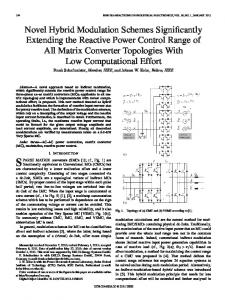
I. INTRODUCTION Over the last few years, industry has had an increasing need for ultra-high-speed and high-power-density drives, and the trend to more compact and higher speed drives continues. For instance, in the PCB drilling industry the trend is to produce smaller diameter holes and in order to attain the same productivity as today, the drilling machines have to rotate at much higher speeds (more than 300,000 rpm). The trend for turbocompressors is towards smaller power ratings and with the scaling of turbo machinery, therefore require higher speeds [1], [2]. One application is in a fuel cell air compressor that requires 120,000 rpm at 12 kW [3] and another is in a 70,000 rpm, 131 kW turbo compressor connected to a PM machine and inverter [4]. Future automotive fuel cells will require low power compressors, which are small and lightweight, and directly driven by high-speed electrical drives. Ultra-micro gas turbines with power outputs up to several hundred watts are being investigated for use in portable power applications [5]. Fig. 1 presents the various application areas for ultra-high-speed machines and shows the power and speed ranges in which they are concentrated. For a 1 kW system, speeds in excess of 300,000 rpm are classified as ultra-highspeed applications. It is predicted that the speeds will reach close to 1 million rpm in some emerging applications. A key technology for all ultra-high-speed rotating machinery is the bearing system. In principle, the possible choices for the bearings are high-speed ball bearings, static and dynamic fluid bearings, foil bearings or magnetic bearings. Except for the ball bearings, all other bearing types require a rather complex design process, however, they show a big advantage compared to the ball bearings. These other bearing
rotational speed (rpm)
Power Electronic Systems Laboratory ETH Zurich Zurich, 8092 SWITZERLAND
[email protected]
10
ETH research
6
emerging applications
10
micro turbines and compressors
pcb drills
5
industrial gas turbines 10
electrical drives magnetic bearings trends
4
10
0
10
2
4
10 drive power (W)
10
6
10
8
Fig. 1. Application areas for ultra-high-speed drives and magnetic bearings.
types rotate in air or another fluid, and therefore have no wear, and are only subjected to air friction. Furthermore, ball bearings are not well suited for operation at high temperatures, which are typical for a gas-turbine generator. With higher rotating speeds, the increased friction losses in the form of heat can change the properties of the lubricant and finally be destructive for the ball bearing. Fluid bearings as well as magnetic bearings minimize this problem. Therefore, even if ball bearings are a possible option, the bearing types with reduced friction losses are preferred. A short summary of the different bearing types is given in Table I. The big advantage of magnetic bearings is their controllability. Active magnetic bearings can cancel or damp instabilities occurring at high speeds [6]. This advantage comes with the cost of an additional power electronics device that controls the bearing forces. This paper presents the design and mechanical construction concept for a combined radial-axial magnetic bearing for ultrahigh speeds. The bearing is constructed together with a 1 kW, 500,000 rpm permanent-magnet machine developed at ETH [7]. The machine and the magnetic bearings are integrated into one system and the power and control electronics for both drive and bearing are optimized for ultra-high-speed operation and minimal volume. The motivation for this work is to design an active magnetic bearing for ultra-high-speed applications and as a first step towards the realization of a hybrid bearing that combines the advantages of fluid bearings and magnetic bearings. Using a fluid bearing as main supporting component allows a smaller and less complex magnetic bearing to be used.
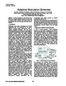
TABLE I COMPARISON OF DIFFERENT BEARING TYPES Bearing Type
Magnetic
Fluid Bearings
Ball Static Dynamic Foil
Pros No wear Lifetime Controllability Small size Availability Exact positioning Lifetime Small size Small size
the same magnetic flux density is created in the air gap for both possibilities. However, the permanent magnet has a high reluctance and with a proper design of the magnetic circuit, the additional air gap created by the permanent magnet, does not need to have an influence on the control flux paths and therefore does not require the use of larger control coils. Fig. 3 (b) shows the influence of biasing the magnetic bearing. Due to the quadratic relation between the carrying force and the magnetic flux density, the same small control current can be used to produce more force after biasing with a permanent magnet (ΔF1