ISSN (Print) : 2319-8613 ISSN (Online) : 0975-4024
Rajani Katiyar et al. / International Journal of Engineering and Technology (IJET)
Novel precoding algorithm for VDSL-2 Rajani Katiyar #1, Padmaja. K .V *2, #1
Assistant Professor, Department of Electronics and Communication Engineering RV College of Engineering, Bengaluru, India 1
[email protected] *2 Professor and Associate Dean, Department of Electronics and Instrumentation Engineering RV College of Engineering, Bengaluru, India 2
[email protected] Abstract— We propose a novel concept of symbol relocation for the improvement of received signal power in diagonal precoder. In the past, many precoding algorithm have been proposed, they all suffer either in terms of low bit rate, high complexity and less received signal power. The proposed symbol relocation concept in diagonal precoder gives high data rate with high received signal power. Complexity of the diagonal precoder has been checked using digital signal processor starter kit -6713, a 32 bit floating point digital signal processor. Our results shows that there is improvement in received signal power by 20 dB while maintaining the same bit rate with low complexity of the system. Keywords— VDSL (Very high speed digital subscriber line), Precoder, PSD (Power spectral density), DSL (Digital subscriber line). I. INTRODUCTION Digital subscriber line is a very old broadband communication technology, which use the potential of exiting twisted pair telephone line. It provide services such as high speed internet access, voice and multimedia communication over conventional telephone line which is already installed for residential and official use to home and in offices. In the present scenario when all the devices are going to connect through internet, there is requirement of high band width. To full fill the requirement of high speed transmission, DSL technology shifted from Asymmetric digital subscriber line (ADSL), Very high speed digital subscriber line (VDSL), VDSL-2 to Fiber to the transmission point (FTTx) and Giga bit fast transmission (G –Fast) with the data rate up to 100 Mbps.VDSL-2 is advance form of VDSL and operate at frequency range of 30 Mhz. Advance version of xDSL is G-fast, which work at the frequency range of 100 Mhz. At higher frequencies, the problem due to electromagnetic coupling between twisted pair wire will also increase. One of the solution to minimize electromagnetic coupling is to decrease the length of wire from 1kilometer (as in ADSL) to 400 meters. Develop new crosstalk minimization algorithm for the improvement in data rate. Crosstalk is classified in two types, Near end crosstalk (NEXT) and Far end crosstalk (FEXT). Effect of crosstalk on wire pair is shown in Fig. 1.
Fig.1. NEXT and FEXT effect in channel [ref-9]
In downstream transmission, crosstalk on the transmitter side can be cancelled using precoders. It is used to predistort the information bearing signal before passing through the channel. Precoders are broadly classified into two types, linear and nonlinear precoders. Linear precoders suffer due to additional transmit power requirement and high complexity of the system. Complexity of the system can be reduced with the help of high speed DSP processor like, DSK 6713 floating point processor [1]. Nonlinear precoders are used to compensate the problem of linear precoders, but it requires, additional change in modem on the customer side. In this paper, we propose the Novel concept of symbol relocation in the constellation plane. It maximize the received signal power in the linear precoders while maintaining the same data rate. Data rate has been measured with, linear and nonlinear precoders for near far scenario of twisted pair channel. The paper is organized as follows. Vectored transmission has been explained in Section II. Details of precoding algorithms for downstream transmission are given in section III. Simulation and results for bit rate performance and received signal power are given in section IV. Conclusion and future scope are summarized in section V and VI.
DOI: 10.21817/ijet/2017/v9i5/170905022
Vol 9 No 5 Oct-Nov 2017
3504
ISSN (Print) : 2319-8613 ISSN (Online) : 0975-4024
Rajani Katiyar et al. / International Journal of Engineering and Technology (IJET)
II. VECTORED TRANSMISSION Precoding in downstream transmission and crosstalk canceller in upstream transmission, in combine is known as vectoring. Vectoring is an advance technique used for crosstalk cancellation in broadband communication using twisted pair wire. In downstream transmission, the crosstalk due to electromagnetic coupling can be minimized by precoders. The purpose of precoder is to pre-distort the information bearing signal according to the variation of channel. Pre-distorted signal on the transmitter side can cancel the crosstalk effect on the received side. There are many type of precoders which are used in vectored DSL. The precoders are broadly classified as linear precoder and nonlinear precoder. Zero forcing and Diagonalization precoders are linear precoder and Thomlinson Harashima (TH) is one of example of nonlinear precoder, SVD (Singular value decomposition) is used for crosstalk minimization in both downstream and upstream transmission. Fig. 2 gives detail about DSL access multiplexing (DSLAM) block, which is responsible for pre-compensation and post compensation in downstream and upstream transmission respectively. Precoders shift the position of information bearing signal based on reverse of the distortion in channel characteristics, it is known as pre-compensation signal. When precompensated signal pass through channel, distortion due to crosstalk present in the channel get the precompensated signal back to its original position.
Fig. 2. Vectoring operation on transmitted signal [ref-11]
System Model In DSL network, there are set of users defined as, 1, . . , working on different frequency tones 1, . . .The response of the system model at each frequency tone k is given in equation (1), (1) ≜ ,..., denotes a transmitted signal of all users at frequency tone k, here is the Vector ≜ ,..., and ≜ ,..., are transmitted signal of the first user at frequency tone k. Similarly, the received signal vector and Adaptive white Gaussian noise (AWGN) noise vector respectively for all users at is defined as N*N matrix of twisted pair wire. In this model the frequency tone k,channel characteristic transmitted signal is same as information bearing signal. Bit rate for different users at particular frequency tone k is based on the received signal power and noise content at that particular frequency k. Total noise at the receiver side is some of the AWGN noise and the crosstalk between twisted pair wire. Bit rate for particular user n at frequency k without precoding is given in equation (2), , (2) ≜ 1 ⎾∑
,
with reference to equation (2), power spectral density of the transmitted signal is defined as,
≜∈ |
| / ∆
Where ∙ , is the expected operator and ∆ is frequency tone spacing in particular modem. Noise power spectral density ≜∈ | | / ∆ is defined for user n on frequency tone k. Symbol is function of coding gain and noise margin. III. PRECODING ALGORITHMS Precoders are used for crosstalk cancellation in downstream transmission. It is used to pre-distort the information bearing signal, based on prior information about channel characteristics. Block diagram of Transmitted signals are shown in Fig. 3.
DOI: 10.21817/ijet/2017/v9i5/170905022
Vol 9 No 5 Oct-Nov 2017
3505
ISSN (Print) : 2319-8613 ISSN (Online) : 0975-4024
Rajani Katiyar et al. / International Journal of Engineering and Technology (IJET)
Fig. 3. Block diagram of Transmitter
Precoders are divided into two categories, linear and nonlinear. Precoder can improve the performance in terms of data rate for downstream transmission. Bit rate calculation using linear and nonlinear precoding algorithms for downstream transmission are given below in detail. 1) Zero Forcing Precoder: Zero forcing precoder, works on basic precoding algorithm, it use inverse of the channel characteristics for precoding. Information bearing signals are pre-distorted using inverse of the channel is the inverse of the channel characteristics, then the characteristics. If is information bearing signal and transmitted signal of zero forcing precoder is define as, . The output response of zero forcing precoder is given in equation (3), (3) , Pre distortion of Equation (3), can further simplify to get output signal on the receiver side is, the information signal with inverse of the channel characteristics, cause increase in the power of the transmitted signal above the spectral mask constraint. The increase in access transmit power can be minimized by use of scaling factor. The precoded signal can be multiplied by the scaling factor before transmission through the channel. Many algorithms have been proposed in the past for the calculation of scaling factor. Reference [2], the scaling factor has been calculated based on
,
As in [2], the scaling factor was same for all the users and considered as the maximum among all the values, . The out-put of the received signal is scaled by constant value and the received signal is given ≜ in equation (4), (4) 2) Diagonalization Precoder: This precoder is very much similar to Zero forcing precoder, except the concept of scaling factor. In [2], further modification in the scaling factor has been done to improve the bit rate of individual users, now the scaling factor is different for individual users. The scaling factor for diagonal precoder is as follows,
,
∈
,
The output signal of diagonalization precoder (DP) is given as,
The bit rate of individual user for (DP) can be calculated as, ,
1
̃
(5)
∗⎾
3) Expanded Constellation Precoder: The Authors of this paper, have proposed the new algorithm for further minimization of transmitted signal power and to improve the received power gain. This algorithm works on the principle of expanded constellation mapping [3], the transmitted symbol on each tone has to be re-mapped with the best possible symbol among the expanded constellation set. The best possible symbol can be found by optimization. and is the range of The new collection of expanded constellation set for kth symbol is, ,⋯ , expanded symbols. The best possible symbol for individual user can be calculated using optimization is given in equation (6), ‖ (6) ̃ arg min ‖ ∈
DOI: 10.21817/ijet/2017/v9i5/170905022
Vol 9 No 5 Oct-Nov 2017
3506
ISSN (Print) : 2319-8613 ISSN (Online) : 0975-4024
Rajani Katiyar et al. / International Journal of Engineering and Technology (IJET)
, is the diagonal elements of the channel matrix. For the best possible value of refer to equation (6), the minimum value of scaling factor is define as, ‖ ‖ Transmitted signal based on expanded constellation precoder is defined as, 1 ∗ ∗ ̃ The output of Expanded constellation precoder is define as, 1
∗ ̃
4) Thomlinson Harashima Precoder: Thomlinson Harashima precoder is a type of non-linear precoder, which recursively cancel the far end crosstalk. The operation of crosstalk cancellation is defined in two steps. In very first step, the intermediate signal is written in the form of non-linear difference equation and later use of modulo operation. Due to this non linearity, the signal power of the transmitted signal will increase to some extent. The purpose of this modulo operator is to fix some bound to avoid access energy in the intermediated symbols [4]. The structure of Thomlinson Harashima precoder is shown in Fig. 4,
Fig.4. Thomlinson Harashima precoder [ref-10]
In this algorithm, channel matrix decompose in the form of unitary matrix and upper triangular matrix as, ∗ , the symbol is the conjugate of the (channel matrix) . The information bearing signal is converted into intermediate transmitted signal , which is later passed through by unitary matrix . The unitary matrix is used to rotate the signal space, so there is no further improvement in signal energy. The received signal after Precoding is given as which further simplifies as, For crosstalk free reception in Thomlinson Harashima (TH) precoder is defined as,
For crosstalk free reception in Thomlinson Harashima (TH) precoder is defined as, (7) The symbol , is the diagonal values of upper triangular matrix, equation (7), can further simplifies in terms of matrix as shown in equation (8), ,
0 ⋱ 0
0 0
,
0 0
⋮
,
0 …
,
,
,
,
0
…
0
…
,
⋮
(8)
Equation (8), can further simplified in terms of difference equation (9),
(9)
⋯
During this operation, there is increase in energy of the intermediated transmitted signal . The access energy can be minimized using modulo operation on the transmitter side. Mathematically modulo operation is √
defined as,.
≜
√
√
. The intermediated transmitted symbol of TH precoder using modulo
operation is given in equation (10),
DOI: 10.21817/ijet/2017/v9i5/170905022
Vol 9 No 5 Oct-Nov 2017
3507
ISSN (Print) : 2319-8613 ISSN (Online) : 0975-4024
Rajani Katiyar et al. / International Journal of Engineering and Technology (IJET)
,
,
,
(10)
The bit rate for an individual user using Thomlinson Harashima precoder are given in equation (11), ,
1
(11)
⎾
5) Singular value decomposition Precoder: Singular Value Decomposition are basically used, when transmitter and receiver are co-located. SVD use precoding for downstream transmission and crosstalk cancellation in upstream transmission. In this algorithm, channel matrix H, decompose in three sub matrix. (12) ⋀ and are unitary matrix which are orthogonal to each other. Precoding matrix work at transmitter and work as equalizer at the receiver. Matrix ⋀ , can work as virtual channel. The received signal at receiver is define as .The received signal at the receiver is achieved after the modification of actual signal with is which can be simplified further in equation (13) , (13) Equation (13), can further simplifies as,
∧
The bit rate of the SVD precoder is calculated as, (14)
,
1
⎾
IV. SIMULATION AND RESULT In this section, we evaluate the performance of received signal power for diagonalization precoder using expanded signal constellation method. Bit rate has been calculated using linear and nonlinear precoder for VDSL-2.The VDSL-2 is the extended form of VDSL and works on the frequency range of 30 Mhz. Per line transmit power for simulation are considered as 4dB.The AWGN noise are considered for simulation with noise PSD of -140 dBm/Hz and coding gain is considered as 12 dB. Complete operating bandwidth of VSDL-2, is divided in different sub carrier and frequency tone spacing between subcarrier is 4.3125 Khz. Spectral mask constraints are considered from [5] [6] .Four cables in a binder are used for modeling of MIMO channel matrix [7]. Each cable is made of twisted pair wire of diameter 24 gauge and considered as cable of unequal length (0.5, 1.0, 1.5, 2.0 kfeet). The channel characteristics are define as, (15) , Channel gain (H), is proportional to propagation constant and length of wire (d). Propagation constant in equation (15), is define in terms of R (resistive), L (inductive), C (capacitive), G(conductive) parameters. For downstream communication at Mhz frequency range, channel characteristics behave as, row wise diagonal dominated (RWDD). In RWDD channel, the value of direct channel coefficient in a matrix is higher than the off diagonal value in a channel, due to crosstalk coupling between a pair of wires. The crosstalk coupling in each wire pair is taken from [8] to simulate complete Multiple input multiple output (MIMO) channel matrix. QAM is used as modulation technique for the transmission of signal. Simulation parameters are given below in Table1. TABLE-1 SIMULATION PARAMETER
Parameter Wire type Carrier spacing Band plan Capacity gap Noised PSD Signal power Crosstalk coupling Length of wire
DOI: 10.21817/ijet/2017/v9i5/170905022
Value 24 gauge twisted pair 4.3125 kHz 30 Mhz 12 dB -140dBm/Hz 4 dB 12.5dB (0.5, 1.0, 1.5, 2.0 ) kfeet
Vol 9 No 5 Oct-Nov 2017
3508
ISSN (Print) : 2319-8613 ISSN (Online) : 0975-4024
Rajani Katiyar et al. / International Journal of Engineering and Technology (IJET)
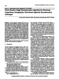
Expandedd constellationn mapping, is symbol optim mization techn nique used forr the improvem ment of receiv ved power gain in dB. Received power p gain in the expandedd constellation n mapping hass been improvved by the min nimization C result of receeived power gain, with exxpended consstellation map pping and of scalinng factor β. Comparative without symbol s mappiing is shown in i Fig. 5, for the 400 toness. There is varriation in received power gaain due to different scaling factoor. We can easily e make-oout the impro ovement in thhe received ppower in dB by using expendedd constellationn mapping.
F 5. Received power Fig. p gain analy ysis of DP precodeer
m operattion used in TH T precoder are a shown in Fig. 6. It shoows the shift of o symbol The perfformance of modulo away froom the originaal symbol possition. As the distance of symbol s move away from oorigin increasee, there is increase in the symbool energy. Modulo operatioon are used affter precodingg to bound thee symbol enerrgy in the limited raange.
Fig. 6. Moddulo operation in TH precoder
mbol has to get g back to thee optimum sym mbol position.. Fig.7, gives the clear idea about the At the receiver, the sym m position of reeceived symbbol before deteection. To recover the origiinal symbol onn the receiverr side, one optimum more moodulo operatioon has to be used u at the reeceiver. Requiirement of additional moduule on the recceiver and transmittter side is one of the big draawback for Thhomlinson Haarashima preccoder. This preecoder does not n require additionaal power for thhe transmissioon of informattion bearing siignal or pre-cooded signal.
Fig. 7. Receivved symbol using g TH precoder
DOI: 10.21817/ijet/2017/v9i5/170905022
Vol 9 No 5 Oct-Nov 2017
3509
ISSN (Print) : 2319-8613 ISSN (Online) : 0975-4024
Rajani Katiyar et al. / International Journal of Engineering and Technology (IJET)
In SVD precoder, the precoding matrix is used on the transmitter side. There are increase in symbol energy due to precoding, which can be minimized by equalizer matrix used on the receiver side. The original symbols, precoded and recovered symbols can be seen in the Fig. 8. In the below Fig, there are increase in symbol energy for the precoded symbol due to shift in symbol position away from origin. Energy are measured as the distance of the symbol from origin. At the receiver side, due to the presence of matrix , the received signals are coming back to their original symbol position which can be detected after optimization.
Fig. 8. Precoded and recoverd symbol in SVD precoder
Bit rate performance of four users of different length has been shown in Fig. 9. Diagonalization precoding, TH and SVD precoding algorithms has been used for data rate calculation from the same information bearing symbol. Simulation of the code is done on Matlab 2015. Result shows that there is good improvement in the data rate with the use of precoders in downstream transmission for VDSL-2. Comparative data rate for all three precoders are also plotted. Among the three precoders, the performance of SVD precoder are better than the Diagonal precoder and Thomlinson Harashima precoder. The rate reach profile are plotted between data rates (Mbps) and length of the wires (kfeet). Bit rate of individual users are given in Table-2.
Fig. 9. Rate reach profile using different precoders for VDSL-2 TABLE II BIT RATE for USER with DIFFERENT PRECODING ALGORITHMS
Precoding technique SVD precoder
Bit rate (bps) 2.7421* 10^(8)
Bit rate (bps) 1.284*10^(8)
Bit rate (bps) 0.5859*10^(8)
Bit rate (bps) 0.3354*10^(8)
DP precoder
1.5500*10^(8)
0.5005*10^(8)
0.2279*10^(8)
0.130*10^(8)
TH precoder
5.6610*10^(7)
2.5695*10^(7)
1.4652*10^(7)
0.9409*10^(7)
No precoder
3.8751*10^(4)
1.2512*10^(4)
0.5697*10^(4)
0.3254*10^(4)
DOI: 10.21817/ijet/2017/v9i5/170905022
Vol 9 No 5 Oct-Nov 2017
3510
ISSN (Print) : 2319-8613 ISSN (Online) : 0975-4024
Rajani Katiyar et al. / International Journal of Engineering and Technology (IJET)
V. CONCLUSION Different precoding algorithm for the bit rate improvement has come, but they all were having constraints with respect to complexity of the system and power cut off. The novel precoding algorithm can minimize the complexity as well as, it will improve the received power gain in dB. The performance of diagonal precoder, has been improved with all three aspects. From the above result authors can conclude that, the diagonal precoder gives the appropriate result without any modification on the customer equipment. Thomlinson Harashima and Singular value Decomposition precoder need small modification on the customer equipment. VI. CHALLENGES and OPPORTUNITY Vectoring is one of the latest technology for the crosstalk cancellation in VDSL-2 and G-fast. The characteristic of channel matrix vary with the operating frequency range. There is a need of innovative crosstalk cancelation technique which can work at 200 Mhz frequency range. Further performance of the system can be improved for 30 Mhz frequency range using some modification in old precoding algorithms. In Thomlinson Harashima precoder the order of wire in a binder can also affect the data rate. We can use innovative search algorithm to provide high data rate for the high end user or enable vectoring for particular line that get maximum benefit. Vectoring technique can be used for non-vectored line with the help of pilot sequence. Development of new adaptive algorithm which can reduce the power from non-vectored line and can improve the rates for vectored line. There is a need of a new algorithm which can disabled particular frequency tone which is highly affected by radio frequency or time varying interference. ACKNOWLEDGEMENT The authors are thankful to the management of R.V. College of Engineering, Bengaluru, India and Visvesvaraya Technological University, Belgaum, for their kind support. REFERENCES [1]
Rajani Katiyar, Padmaja K.V,”Performance of Zero forcing pre coder for vectored DSL,” in Proc. IEEE international conference (TENCON), Singapore, 2016, pp. 1851-1855. DOI: 10.1109/TENCON.2016.7848564 [2] Christopher Leung, Sean Huberman, Khuong Ho-Van, and Tho Le-Ngoc,” Vectored DSL: Potential, Issues and Challenges,”IEEE Communications surveys & tutorials, vol. 15, no. 4, 2013. [3] Rong Zhang, Anas F. Al Rawi, Leslie Derek Humphrey, and Lajos Hanzo,”Expanded Constellation Mapping for Enhanced Far-EndCross-Talk cancellation in G.fast,” IEEE Letters, vol. 21, NO. 1, January, 2017. [4] George Ginis and John M. Cioffi ,” A Multi-user Precoding Scheme achieving Crosstalk Cancellation with Application to DSL Systems”, IEEE conference, December 2000.DOI: 10.1109/ACSSC.2000.911265 [5] ITU-T standard G.test.bis. [6] ITU-T Recommendation G.993.2-2006: Very high speed Digital Subscriber Line 2 transreceiver. [7] Rajani Katiyar, Padmaja K.V,” Performance analysis of time domain and frequency domain equalizer for ADSL ,” in Proc. IEEE international conference (ICCSP), India, 2016, pp. 0513 – 0516 DOI: 10.1109/ICCSP.2016.7754190 [8] Raphael Cendrillon, Fang Liming, James Chou, Guozhu Long, and Dong Wei,” Challenges and Solutions in Vectored DSL,” SocialInformatics and Telecommunications Engineering Research gate 2010. [9] Thomas starr, Massimo sorbara, John M. Cioffi, Peter J. Silver man, DSL Advances. Prentice Hall communications engineering and emerging technologies series, Pearson Education India 2008, ISBN-8131723070, 9788131723074. [10] George Ginis and John M. Cioffi ” A Multi-user Precoding Scheme achieving Crosstalk Cancellation with,” Application to DSL Systems research gate 2000. [11] www.google.co.in/imgres
AUTHOR PROFILE
Rajani Katiyar is working as Assistant Professor, Department of Electronics and Communication Engineering, RV college of Engineering, Bengaluru. She has got 12 years of teaching experience. She has obtained Bachelor of technology degree from MJPRU Bareilly in the year 2001 and obtained Master of Technology degree from DAVV University, Indore in 2005. Currently she is pursuing Ph.D. from Visveswaraya Technological University, Belagavi, India. She has published 1 paper in National conferences, 2 papers in IEEE International conferences and 2 papers in International journals. Her area of interests includes Broadband Communication and Signal Processing.
Dr. Padmaja. K.V is working as Professor & Associate Dean, Department of Electronics & Instrumentation Engineering, RV college of Engineering, Bengaluru. She has got 26 years of teaching experience and 11 years of experience in R&D. She did her Bachelor of Engineering from Gulbarga University in 1987 and Master of Technology from Pondicherry University in 1991.She received her PhD degree in the year 2010 from Visveswaraya Technological University, Belagavi, India. She has published over 21 papers in National and International conferences and around 14 papers in the International & National journals. She has received Academic Excellence award for the year 2007-08 and 2008-09 by RSST Trust.
DOI: 10.21817/ijet/2017/v9i5/170905022
Vol 9 No 5 Oct-Nov 2017
3511