Survey of long-term durability testing of composites, adhesives and .... 3.7 ENVIRONMENTAL STRESS CRACKING TEST METHODS . ...... Barcol hardness. 5. 5.
NPL Report MAT 85
Survey of Long-Term Durability Testing of Composites, Adhesives and Polymers A.S. Maxwell and W. R. Broughton November 2017
www.npl.co.uk
NPL Report MAT 85
NPL Report MAT 85
Survey of long-term durability testing of composites, adhesives and polymers
A S Maxwell and W R Broughton Engineering, Materials and Electrical Sciences
NPL Report MAT 85
NPL Management Limited, 2017
ISSN 1754 - 2979 Issue 1: May 2017 Issue 2: November 2017
National Physical Laboratory Hampton Road, Teddington, Middlesex, TW11 0LW
Extracts from this report may be reproduced provided the source is acknowledged and the extract is not taken out of context.
Approved on behalf of NPLML by Fernando Castro, Knowledge Leader, Engineering, Materials and Electrical Sciences
NPL Report MAT 85
CONTENTS 1
INTRODUCTION ..........................................................................................................................1 1.1 METHODOLOGY.........................................................................................................................1
2
DEGRADATION MECHANISMS ...............................................................................................3 2.1 TEMPERATURE...........................................................................................................................3 2.2 MOISTURE ...................................................................................................................................4 2.3 WEATHERING .............................................................................................................................8 2.4 IONISING RADIATION ...............................................................................................................9 2.5 CHEMICAL DEGRADATION .....................................................................................................9 2.6 BIOLOGICAL DEGRADATION ...............................................................................................12 2.7 ENVIRONMENTAL STRESS CRACKING (ESC) ...................................................................12
3
ACCELERATED AGEING TEST METHODS ........................................................................14 3.1 THERMAL STABILITY TEST METHODS ..............................................................................14 3.2 LIQUID ABSORPTION TEST METHODS ...............................................................................14 3.3 WEATHERING TEST METHODS ............................................................................................14 3.3.1
Natural Exposure ..............................................................................................................14
3.3.2
Artificial Exposure ...........................................................................................................14
3.4 IONISING RADIATION .............................................................................................................17 3.5 CHEMICAL RESISTANCE TESTING OF GLASS REINFORCED POLYMERS ..................17 3.6 BIOLOGICAL DEGRADATION ...............................................................................................19 3.7 ENVIRONMENTAL STRESS CRACKING TEST METHODS ...............................................19
4
3.7.1
Introduction ......................................................................................................................19
3.7.2
Bent Strip Tests ................................................................................................................20
3.7.3
Bent Strip for Flexible Materials ......................................................................................20
3.7.4
Ball and Pin Impression....................................................................................................21
3.7.5
Constant Tensile Deformation ..........................................................................................21
3.7.6
Slow Strain Rate Testing ..................................................................................................21
3.7.7
Constant Tensile Stress Test .............................................................................................22
3.7.8
C-ring Tests ......................................................................................................................23
LIFE PREDICTION ....................................................................................................................24 4.1 THERMAL AGEING ..................................................................................................................24 4.2 TEMPERATURE-MOISTURE-STRESS SUPERPOSITION ....................................................25 4.3 WEATHERING ...........................................................................................................................29 4.4 IONISING RADIATION .............................................................................................................31 4.5 ENVIRONMENTAL STRESS CRACKING ..............................................................................31
NPL Report MAT 85
5
INDUSTRIAL SURVEY ..............................................................................................................32 5.1 APPLICATIONS .........................................................................................................................32 5.2 TIME-SCALES ............................................................................................................................32 5.3 MATERIALS ...............................................................................................................................33 5.4 DEGRADATION MECHANISMS .............................................................................................34 5.5 FAILURE PARAMETERS .........................................................................................................34 5.6 ACCELERATED TESTING .......................................................................................................35 5.7 METHODS OF ACCELERATION .............................................................................................35 5.8 MONITORING TESTS ...............................................................................................................36 5.9 PREDICTION ..............................................................................................................................37 5.10 FUTURE WORK .........................................................................................................................37
6
SUMMARY ...................................................................................................................................37
7
REFERENCES .............................................................................................................................39
APPENDIX 1
NPL PUBLICATIONS............................................................................................43
APPENDIX 2
STANDARDS ..........................................................................................................46
NPL Report MAT 85
1
INTRODUCTION
Polymer, adhesives and composites are increasingly being used for applications where long-term or critical applications require the use of accelerated ageing regimes to ensure the serviceable life of product and components. A trend that is likely to continue for the foreseeable future due to progressive changes in material procurement strategies that require increased product lifetimes in increasingly harsh environments. As a consequence, there is growing demand on manufacturers to extend the life-time guarantees on products, particularly where inspection can be difficult or failure catastrophic. Regulation and stringent product guarantees are also increasingly being demanded for engineering components in consumer products such as cars and washing machines, where consumers often view extended lifetime warranties as a sign of product quality. Whilst the life expectancy of products in non-demanding applications have traditionally been predicted from previous experience, the use of polymeric materials in long-term or critical applications requires a far better understanding of the failure mechanisms to enable lifetime predictions to be made. This report summarises the degradation mechanisms found in polymeric materials, the accelerated test methods that have been developed and the techniques used for assessing life-time predictions. The results of an industrial survey to determine current practice and the future needs of industry for longterm testing are also presented. Finally, the report contains a summary of previous NPL publication on durability (Appendix 1) and current ISO and ASTM standards (Appendix 2). 1.1 METHODOLOGY The aim of durability testing is to assess the effect that ageing processes have on the in-service performance of products and materials. Natural ageing of materials in-service can be assessed either by conducting a programme of condition monitoring using non-destructive testing (NDT) or by examining parts taken out of service. However, the problem with in-service monitoring is that it can only provide information on the current state of components. It does not provide information on how long a component will remain serviceable. To predict future performance some combination of accelerated testing and modelling is required (Figure 1.1). The exact combination of monitoring, accelerated testing and modelling will vary depending on the application and may not include all three elements. For example, when product life-time predictions are required before a new material or design is put into service it is not possible to conduct representative in-service monitoring, in which case the life-time predictions must depend solely on accelerated test results and analytical methods/modelling used to extrapolate the data. A key component of durability assessments are accelerated tests. The basic concept of these tests is simply to increase the degradation environment, such as temperature or frequency, to levels that are higher than those experienced in service in order to accelerate degradation and reduce the time required for testing. The main restriction to the level of acceleration that can be achieved is that elevated degradation rates may change the mechanisms that occur in the tests from that occurring in-service. The relationship between the degradation agent and time is only likely to be valid over a limited range of acceleration, and regardless of the validity of the mechanisms and extrapolation procedures used the intrinsic experimental uncertainty of the measurements will be magnified the more the results are extrapolated. It is therefore essential that particular attention is paid to the degradation mechanisms and the validity of the predictive techniques used.
1
NPL Report MAT 85
Ideal combination
Figure 1.1 Effect prediction of long-term properties requires a combination of condition monitoring
The key steps in conducting an accelerated test programme for a long-term durability assessment are therefore the following: 1. Define the materials, environmental conditions and the serviceable time-scale that the product will experience in-service. 2. Identify the degradation agents/mechanisms and whether there are any synergistic effects (Section 2). 3. Select the parameters that are to be used to accelerate the tests (Section 3), and identify potential for change in mechanisms. 4. Decide on the monitoring parameters and the measurement techniques used to measure them (Section 3). 5. Select the analytical/modelling techniques that will be used to extrapolate the test data to inservice conditions (Section 4). The testing rational outlined above was that used to develop the questionnaire used to assess current practice and the needs of UK industry (Section 5).
2
NPL Report MAT 85
2
DEGRADATION MECHANISMS
Property changes in polymeric materials can be induced by many different degradation agents acting either alone or more commonly in combination. The most common forms of degradation are: • Thermal - elevated temperatures, sub-zero temperatures and thermal cycling • Moisture - increased humidity, complete immersion in water, spray or dry/wet cyclic conditions • Weathering - ultraviolet exposure combined with rain and/or sand erosion • Chemicals (including acids, alkalis, solvents and oxygen) • Irradiation- ultraviolet or high-energy radiation • Biological - micro-organisms • Environmental stress cracking (combined effect of stress and a plasticiser) • Stress - static and fatigue loads and residual stresses In many applications, materials will be exposed to a combination of two or more degradation agents, often resulting in complex synergistic degradation reactions. Accelerated degradation occurring due to the combined action of two or more degradation agents acting together simultaneously or the degradation from one agent reducing its resistance to another, for example biological degradation occurring in an already partially degraded material. The predominant factors in climatic exposure are moisture, temperature and ultraviolet radiation. The severity of these factors will depend on geographical location, and need to be considered when designing with these materials. 2.1 TEMPERATURE Exposure to elevated temperatures will often produce chemical and physical changes within polymeric materials that lead to degradation of the material. Increasing the temperature accelerates most of the degradation processes that occur in polymeric materials, such as oxidation, chemical attack and mechanical creep. Physical changes include polymer structure shrinkage, pore formation and weight loss through chemical decomposition of the polymer. As the temperature increases, mechanical properties such as stiffness and strength tend to decrease. Oxidation is generally considered to be the most serious problem when using polymers at elevated temperatures with the rate of degradation increasing with the amount of oxygen present [1, 2]. In adhesively bonded joints, the primary path for oxygen diffusion is through the adhesive, which can be relatively rapid at elevated temperatures. Polymer composites are permeable to atmospheric gases, and hence the rate of degradation is considerably higher with the elevated temperatures also degrading the fibre-matrix interface. At extremely high temperatures, as experienced in fires, fibre ablation occurs. The overall degradation process will often involve a relatively long induction period during which little degradation is observed [1-3]. At the end of this period, there is a rapid increase in degradation leading to a significant reduction in the mechanical properties of the polymer. This induction period is temperature sensitive and is reduced significantly at elevated temperatures. The induction period of the degradation process can normally be regarded as the serviceable lifetime of the polymer. Other physical changes can occur in polymers because of temperature changes, one of the most common being thermal expansion. Fibre-Reinforced Plastics (FRPs): In FRPs, differences in thermal expansion between the fibre and matrix can induce stresses, which can degrade the fibre-matrix bond resulting in thermo-mechanical degradation during thermal cycling. The overall degradation process in fibre-reinforced plastics (FRPs) will often involve a relatively long induction period during which little degradation is observed. At the end of this period, there is a rapid increase in degradation leading to a significant reduction in the mechanical properties of the composite. This induction period is temperature sensitive and is reduced significantly at elevated temperatures. The induction period of the degradation process can normally be regarded as the serviceable lifetime of the composite. A sudden brief exposure to high temperatures can result in a phenomenon known as thermal spiking, which can lead to excessive localised stresses with deleterious effects on structural performance. The effects of rapidly driven-off moisture through thermal spiking can also be expected to contribute to damage.
3
NPL Report MAT 85
Adhesives: Similar mechanisms can also occur in adhesive joints. A sudden brief exposure to high temperatures can result in excessive localised stresses forming with deleterious effects on structural performance. Conversely, exposure to low temperatures can result in the brittle fracture of plastics, interfacial fibre-matrix cracking in polymer composites and debonding of adhesive joints. Rapid failure can occur in environmentally degraded polymeric materials at sub-zero temperatures, e.g. due to the formation of ice particles from absorbed water initiating internal fractures. Complete interfacial debonding may occur in multiple component systems exposed to cryogenic temperatures through, for example, the combined effects of differential thermal contraction and embrittlement. 2.2 MOISTURE Most polymeric materials will absorb small, but potentially damaging amounts of moisture from the surrounding environments with the degree of degradation that occurs often being linked directly with the amount of moisture absorbed. Absorbed water may adversely affect polymeric materials in several ways as indicated below: • Dimensional changes (swelling of the material) • Surface degradation and damage (colour, gloss, crazing, blistering, etc.) • Reduction in the glass transition temperature (Tg) • Reduction in mechanical and physical properties (i.e. stiffness, strength and hardness) Although the process of moisture absorption and desorption within the surface layers occurs almost immediately on contact with the environment, moisture diffusion into thick systems is usually a slow process. It may take weeks to months before a substantial amount of moisture has been absorbed and considerably longer periods (i.e. 1-2 years) before the material is saturated. The rate of moisture uptake by a material (i.e. its absorption and diffusion properties) is dependent on factors such as the temperature, relative humidity, exposure time and mechanical load. At elevated temperatures, the rate of moisture uptake and material property degradation is accelerated. The moisture absorption kinetics of polymer systems differs widely both between different grades and with chemical ageing. The presence of tensile loads will also accelerate moisture uptake by opening existing internal cavities or voids, and by contributing to micro-crack formation. A materials system containing micro-cracks will absorb considerably more moisture than an undamaged materials system. This applies equally to polymers, composites and adhesives [4]. Exposing the wet system to sub-zero temperatures can further exacerbate this process. A commonly used test method for polymer composites and bonded adhesives is to subject hot/wet conditioned specimens to thermal cycling in which the composite is exposed to temperatures as low as -55°C for a given number of cycles to assess the laminates crack resistance.
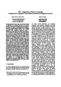
GlassTransition Temperature (K)
600 25oC immersion 40oC immersion 60oC immersion line of best fit
550
500
450
400 0.0
0.5
1.0
1.5 2.0 2.5 3.0 Moisture Content (wt%)
3.5
4.0
Figure 2.1 Glass transition temperature of F922 epoxy as a function of moisture content
4
NPL Report MAT 85
Polymers: Water permeates all polymers to a greater, or lesser degree. Absorption of water is known to cause plasticisation (essentially softening) of the polymer, depressing the glass transition temperature, Tg, and lowering the modulus and strength. Elongation to break (strain-to-failure) tends to increase with moisture content. For example, Tg of a typical polyester resin decreases by approximately 15-20°C for a 2% moisture weight gain. Due to this reduction in Tg it is advisable when using polymeric systems in load bearing structures to ensure that the maximum operating temperature is at least 30-40°C below the Tg of the material (considering moisture effects). Figure 2.1 shows the effect of moisture content on Tg for an epoxy that has been immersed in distilled/deionised water for prolonged periods of time at three different temperatures [5]. The rate of moisture diffusion increases at elevated temperatures. Leaching out of organic additives, such as fillers, catalysts, hardeners, pigments and fire retardants into the surrounding environment can also result in changes in Tg with the loss of fillers and additives becoming more likely with increasing temperature. Permeability is dependent on the structure and chemistry of the polymer. The rate of diffusion in amorphous polymers will depend on the state of the polymer. In the rubbery state (T > Tg), there is substantial “free volume” in the polymer mass and considerable molecular segment mobility, which enables easier passage of moisture through the polymer. In the glassy state (T < Tg), the “free volume” is far less and molecular segments are immobile, and as a result the diffusion rate is lower. Diffusion rates tend to be higher in amorphous (thermoset) polymers compared with thermoplastics. In semi-crystalline polymers, the crystalline regions are almost impermeable due to the ordered arrangement of molecules and high degree of molecular packing in these regions, with diffusion restricted to the amorphous regions. Adhesives: Moisture (water) degradation is probably the major cause of in-service failure in bonded structures. The ubiquitous nature of water combined with the ability to penetrate the adhesive structure poses considerable problems for bonded structures. As previously mentioned, water permeates all polymers to a greater, or lesser degree and in the case of bonded joints water will eventually reach the interfaces between adhesive and adherends where its effect is most damaging. Migration of water to the joint interface will result in permanent loss of adhesion. This highly polar molecule is known to interact strongly with structural adhesive systems containing hydroxyl groups, such as epoxies, polyurethanes and acrylics. Hydroxyl groups are hydrophilic and will form hydrogen bonds with water (i.e. hydrolysis). Hydrolysis causes the polymer chains in the adhesive to break into smaller segments (reversion), thus weakening the bond strength of the polymer. This problem is further exacerbated at elevated temperatures and mechanical stress. Mechanical and thermal properties generally tend to recover on drying, provided irreversible hydrolysis has not occurred. The absorption of moisture by the adhesive may cause the material to swell and deform. Volumetric swelling due to moisture absorption, if significant, may induce additional stresses within the adhesive joint compromising the durability of the joint, and therefore should be included in durability modelling of the adhesive. It is paramount that the adhesive selected for use in an aqueous environment should have low permeability and diffusion coefficient to water and with good design, it is possible to significantly reduce the rate of moisture diffusing to the adhesive/adhered interfaces. As with most materials, each adhesive has specific attributes that provide protection against moisture. The chemistry of most structural adhesives is a compromise between environmental resistance and mechanical performance with the various classes of structural adhesives possessing different levels of moisture resistance. The problem for designers and engineers is selecting an adhesive, which will guarantee the required design life performance in the service environment to be experienced by the bonded structure. There is no single adhesive that offers a universal solution (i.e. protection from all environments). Being impervious to one environment is no guarantee of resistance to other environments. Highly cross-linked adhesives, such as epoxies and phenolics generally have good resistance to moisture and high temperatures. Most thermosetting adhesives in the presence of moisture are susceptible to hydrolysis at elevated temperatures (above 70°C) with considerable loss in mechanical performance. Exposure to hot and humid environments can often cause rapid loss of joint strength within a short duration (i.e. less than 2 years) with catastrophic consequences. Failure invariably occurs at the adhesive/adherend interface. The major cause of strength loss in adhesively bonded metal joints is associated with interfacial degradation through water-substrate interaction rather than weakening of the 5
NPL Report MAT 85
adhesive. In the case of metallic structures, water can degrade the strength of adhesive joints through hydration of metal oxide layers. Corrosion products, such as rust, at the interface are considered a postfailure phenomenon. The presence of water in epoxy adhesives results in plasticisation (essentially softening) of the polymeric material. At temperatures below Tg, polymer property reduction is reversible upon dehydration, whereas above Tg, matrix properties may be permanently degraded. Surface treatments, such as phosphoric acid anodisation (metallic adherends) and organosilane primer coatings will bestow joints with improved moisture resistance. FRPs: In many instances, water reacts with the matrix and causes irreversible chemical changes and diminished performance. Capillary action along the fibres can account for a significant proportion of initial moisture uptake, although a chemically resistant matrix may encapsulate the fibres. Shrinkage of the resin away from the fibres during curing is a contributing factor to the capillary effect. The effect of moisture is to cause hydrolytic breakdown of the fibre-matrix interface resulting in a loss in the efficiency of load transfer between the matrix and the fibre reinforcement.
Figure 2.2 Schematic of the osmotic process – leading to delaminations/blistering
All laminates when exposed to marine environments will allow water vapour to permeate the structure. As the water diffuses into the composite it reacts with any hydrolysable components (e.g. ester groups) inside the laminate to form tiny cells of concentrated solution. Under this osmotic process [6-7] (see schematic in Figure 2.2), more water is drawn through the semi-permeable membrane of the laminate, in an effort, to dilute the solution. The water can increase the fluid pressure of the cell by 50 atmospheres, which eventually distorts or bursts the laminate or gel-coat and can lead to a blistering of the surface. Damage can be very extensive requiring major repair or the replacement of the structure (Figure 2.3).
Figure 2.3 Osmotic blistering of a GFRP boat hull with inset showing laminate breakdown (Courtesy of Minton, Treharne and Davies Ltd)
6
NPL Report MAT 85
Osmosis blistering is a very common problem that occurs in glass fibre-reinforced plastics (GFRP) laminated structures that have been immersed for long periods in aqueous solutions and is often observed in GFRP boats, water tanks and swimming pools. A resin rich layer (e.g. gel coat) is often applied to the composite surface where the material is to be exposed for long periods to aqueous solutions. This protective layer acts as a barrier to moisture ingress, thereby protecting glass fibres from moisture degradation. Although the gel coat protects the underlying composite substrate by slowing water ingress, it is not an impermeable layer. Other protective measures against natural weathering include marine paint and polyurethane coatings, which also shield the composite substrate from UV damage and weathering erosion. Osmotic effects are amplified in the presence of hydrostatic pressure as experienced in sub-sea environments (e.g. submersibles). Simulations of sub-sea conditions have shown that increasing the hydrostatic pressure results in faster diffusion rates. Entrapped air/gas/moisture vapour under pressure expands as the structure is raised from depths (as external pressure decreases), analogous to the effect of the bends experienced by divers. As a result, cracking and delaminations may occur, thus compromising structural integrity. Porous materials can be expected to be far more prone to this effect than well-compacted materials. An increase in porosity results in an increase in both the rate of diffusion (diffusivity) and the level of absorbed moisture at saturation. Other issues to consider in sub-sea applications are the chemical composition and properties of seawater, pressure and depth effects, temperature, salinity, dissolved oxygen content, pH level, oceanic currents and biological attack. Freeze and freeze-thaw exposure are also of concern to engineers and designers of composite structures, particularly in the presence of moisture. Published information on the effect of freeze-thaw on FRPs is very limited; however, the effects of low-temperature thermal cycling are reasonably well understood. At low temperatures, the presence of residual stresses resulting from a combination of resin shrinkage and differential thermal contraction between reinforcement and resin matrix can result in the formation of micro-cracks in the matrix and fibre–matrix interface. The degree of microstructural damage, whose presence adversely affects laminate stiffness and strength properties, dimensional stability and fatigue resistance, is directly related to the extent of resin shrinkage during cure. Residual stresses increase as the temperature is decreased. Laminates containing significant amounts of moisture will experience severe stresses if the laminate becomes frozen due to the expansion of water when it freezes. This expansion can generate significant pressures in a laminate contributing to the initiation and growth of micro-cracks and delaminations. The resultant damage is associated with free moisture (ice particles) present within voids (cavities) and cracks rather than matrix swelling induced through moisture absorption. The severity of damage and subsequent deterioration of laminate properties increases with thermal cycling. An increase in damage also lowers the composite’s resistance to further moisture ingress. Fibre degradation is primarily an issue for glass fibres and aramid fibres, with carbon fibres being stable in most environments (NB. Carbon fibres are relatively insensitive to moisture, and hence the variability in the tensile breaking stress and strain for carbon fibre tows is noticeably lower than for Eglass fibre and aramid fibre tows). Exposure to humid air (including environmentally controlled laboratories at standard conditions, i.e. 23°C and 50% relative humidity (RH)) will compromise the load-bearing capacity of the fibres, resulting in a loss of stregth and an increase in strength variability [8]. For example, the tensile strength of freshly drawn E-glass fibres is typically 3.5 GPa, however exposure to atmospheric moisture can lead to a reduction in strength (tensile strength is typically 2.0 GPa, or less). The loss of tensile strength of E-glass fibres is dependent on exposure time, temperature and degree of humidity. On initial exposure to a humid/water environment, the rate of fibre degradation is relatively rapid, even in benign environments, such as air-conditioned laboratories. The tensile strength is reduced to 3.0 GPa after 3 weeks exposure to standard laboratory conditions. Immersion in water at ambient temperature for the same period results in a 20% reduction (~2.5 GPa). The original tensile strength can be fully realised, provided the fibres are carefully handled during fabrication to avoid surface damage and are stored in a dry environment. An intrinsic tensile strength of 2.0 GPa is often assumed for design purposes. The effect of moisture on aramid fibre-reinforced epoxy laminates is potentially greater than other composite systems.
7
NPL Report MAT 85
Degradation of E-glass fibres in water can be mainly attributed to leaching of alkali oxides (sodium and potassium oxide) from the fibre surface resulting in the formation of surface micro-cracks, which act as stress concentrators. The loss of strength can be expected to be permanent at all conditioning temperatures and exposure times. The water surrounding glass fibres evolves into an aggressive alkali solution as the alkali ions dissolve out of the glass, slowly decomposing the glass fibres. Increasing the alkali content of the glass tends to reduce environmental attack from water and alkali solutions. It is worth noting that deionised water is slightly more aggressive than either tap water or seawater. Drying of the composite will remove most of the skin of water adjacent to the fibre, but a small permanent layer with retained water will remain, and the mechanical properties of the fibre will be permanently degraded (for further details on chemical degradation see references [9,10]). Aramid (e.g. Kevlar 49) fibres tend to absorb moisture and degrade at room temperature with the rate of degradation accelerating as temperature is increased. Substantial hygrothermal strength losses have been observed with these materials, particularly under natural weathering conditions (i.e. combination of moisture and ultraviolet light). 2.3 WEATHERING Weathering or more specifically photo-oxidation of polymers refers to the chemical and physical changes that occur when UV radiation is absorbed by a polymer. The UV radiation spectrum comprises wavelengths of between 290 and 400 nm, which corresponds to energies of between 415 and 300 kJ/mol. These energies are in the same range as the bond energies of many organic compounds. Geographical location, seasonal variations and time of day play a significant role in the length, intensity and wavelengths experienced. Equatorial latitudes are particularly hostile in terms of UV exposure, where due to the high solar angle the levels of UV radiation and temperature are higher and the range of wavelengths transmitted by the earth’s atmosphere extends even lower (i.e. shorter wavelengths). At higher altitudes, a thinner atmosphere absorbs less UV radiation. The presence of water increases UV degradation, because the dissolved oxygen in water is more active in promoting photo-oxidation than oxygen in the air. Chemical reactions are induced when specific functional groups absorb the UV radiation. Free radicals liberated in the process will trigger further reactions. The deleterious effect will be dependent on the chemical nature of the material, environmental factors such as temperature and humidity, and exposure time. Material changes include discoloration (yellowing and bleaching), embrittlement, and loss of mechanical and physical properties. Photo-oxidative sensitivity also tends to increase increase with prolonged exposure to pollutants, such as nitrogen dioxide [3, 10, 12]. Geographical location, seasonal variations and time of day play a significant role in the length, intensity and wavelengths experienced. Equatorial latitudes are particularly hostile in terms of UV exposure, where due to the high solar angle the levels of UV radiation and temperature are higher and the range of wavelengths transmitted by the earth’s atmosphere extends even lower (i.e. shorter wavelengths). At higher altitudes, a thinner atmosphere absorbs less UV radiation. The presence of water increases UV degradation, because the dissolved oxygen in water is more active in promoting photo-oxidation than oxygen in the air. Photo-degradation is initiated by solar radiation, which results in the absorption of UV radiation by chromophores and in the activation of excited states in macromolecules. When a polymer is exposed to solar radiation the energy absorbed by the polymer results in the formation of free radicals within the polymer by the dissociation of the C-H bonds in the polymer chains. The extent of this chemical reaction depends on the radiation exposure that is the quantity of ultraviolet light (50
A2 1.1 1.2 1.3 1.4 Unsuitable for purpose
3.6 BIOLOGICAL DEGRADATION Biological attack of polymers is extremely difficult to accelerate to any great extent as it depends on simulating the activities of living organisms. A standard procedure for assessing the resistance of plastics to bacterial and fungi attack is described in ISO 846 [46]. This laboratory procedure essentially involves exposing the specimens to specific bacteria and controlling the environmental conditions to accelerate biological attack of the specimens. The level of biological activity in the test is assessed by comparing the biological degradation of the polymer to that of a cotton strip. 3.7 ENVIRONMENTAL STRESS CRACKING TEST METHODS 3.7.1 Introduction The evaluation of ESC resistance is covered by several national and international standards [47]. These test methods can be divided roughly into two groups those that are based on an applied deformation and those based on applied load. The main international standards for testing ESC resistance are:
19
NPL Report MAT 85
Constant deformation tests • Bent strip [48] • Bent strip test for flexible materials [49] • Ball and pin impression [50, 51] • Constant tensile deformation [52] • Slow strain rate testing [53] Constant load tests • Constant tensile stress [54] • C-ring tests [55] The following section gives a brief overview of the ESC test methods that have been standardised. More detailed information about these and other non-standard test methods can be obtained from a technical review on ESC test methods produced by Turnbull and Maxwell [47]. 3.7.2 Bent Strip Tests The bent strip test (ISO 4599) [48] involves clamping the test specimen to a semi-circular former to apply a known strain to the specimen. The radius of curvature of former can be varied to induce different levels of strain in the specimen. This strain may be calculated using the following equation:
ε (%) =
d × 100 2r + d
(3.1)
where d is the thickness of the specimen and r is the radius of the former. Once the specimen has been strained it is brought quickly into contact with the chemical environment. After an agreed time, the specimens are removed from the apparatus and either visually inspected for crazing or mechanically tested to assess their residual strength. This test is most commonly used for assessing the ESC susceptibility of amorphous polymers. It is not suitable for semi-crystalline polymers, which are susceptible to rapid stress relaxation, as the stress applied to the specimen will decrease during the test. 3.7.3 Bent Strip for Flexible Materials This test was developed by Bell laboratories in the USA and has since been standardised as ASTM D1693 [49]. The technique is suitable for flexible polymers such as polyethylene, but should only really be used for quality control purposes.
Figure 3.5 Bent strip technique for flexible polymers [49]
20
NPL Report MAT 85
An illustration of the type of apparatus used in this test method is shown in Figure 3.5. The specimens used in this test are notched rectangular strips (38 × 13 × 3 mm) that are clamped in a jig so that the sample folds over on itself at an angle of 180° to produce stress within the specimen. Once loaded into the jig the specimens are immediately exposed to the chemical environment at the required test conditions. The specimens are then inspected visually at given time intervals and the time required for 50% of the specimens to fail is noted. 3.7.4 Ball and Pin Impression The ball and pin impression test [50, 51] is used primarily for complex finished components. The method involves drilling a series of holes of a specific diameter into the polymer. A series of oversized balls or pins are inserted into the holes to induce a range of different stresses. One hour after the pins have been inserted the specimens are immersed in the environment for 20 hours. The specimens are then dried and visually examined for crazes. The smallest ball to cause visible crazing is used to determine the ESC resistance of the polymer. 3.7.5 Constant Tensile Deformation The constant tensile deformation test is a relatively new test that is currently being developed as an ISO standard as ISO 22088 Part 5 [52]. The test method involves applying a constant deformation to the specimen and monitoring the stress relaxation that occurs while it is immersed in the chemical environment. The test is repeated using progressively smaller levels of deformation until the stress relaxation curves of consecutive tests superimpose on one another Figure 3.6. The applied stress required to produce this level of deformation is defined as the critical stress. The ESC resistance of the material is determined by comparing the critical stress obtained in the test environment to that obtained in air.
Figure 3.6
Stress relaxation curves obtained using progressively smaller levels of deformation (1>5) until consecutive curves superimpose on one another (4 and 5) [52]. Note: S0 is the initial stress and S is the stress at time t
3.7.6 Slow Strain Rate Testing The slow strain rate method has been used only comparatively recently for characterising the performance of plastics although it is well-established for metals and it has been now been developed into a standard [53] as ISO 22088 Part 6. The test method involves subjecting a specimen to a gradually increasing strain at a constant displacement rate whilst it is exposed to the chemical environment. The tests are conducted under uniaxial tension at low strain rates to enhance the influence of the environment on the specimen. Load and displacement are monitored continuously to enable stress-strain curves to be produced. 21
NPL Report MAT 85
The development of crazes within the specimen causes the strain to be taken up locally at the crazes such that the stress required to deform the specimen is reduced compared to that in an inert environment. The onset of craze initiation can therefore be detected by the departure of the stress-strain curve in the chemical environment from that in air Figure 3.7. The main advantages of the slow stain rate test are that it is relatively rapid, requires few specimens and can be automated. 60
Stress (MPa)
50 40 30
Departure 20
Air Test Medium
10 0 0.00
0.01
0.02
0.03
0.04
0.05
Strain
Figure 3.7
Typical stress-strain plot showing difference in stress/strain profile for material exposed in air and in the test medium [53]
3.7.7 Constant Tensile Stress Test The distinctive feature of this test is that a constant load is applied to the specimens, thereby avoiding the problem of stress relaxation that is found in the constant strain test methods [54]. An illustration of the type of apparatus used in this test method is shown in Figure 3.8. The technique involves subjecting the specimen under investigation to a constant tensile stress at a stress below the tensile yield stress of the polymer. This is usually achieved using a dead weight that is suspended from one end of the specimen. The specimen is then immersed in the stress-cracking agent and inspected at regular intervals to establish the onset of crazing. The time required for crazes/cracks to appear after the specimen has been exposed, or the threshold stress below which no crazes appear in a specific time-period (typically 100 hours) can be used as a measure of the ESC resistance.
Figure 3.8 Illustration of typical apparatus used for a constant load test [54]
22
NPL Report MAT 85
3.7.8 C-ring Tests C-ring specimens are often used for the testing of tubing and pipe and have been standardised for the testing of polyethylene pipes in ASTM F-1248 [55]. Typical apparatus for testing C-ring specimens is shown in Figure 3.9. Circumferential stress is of principle interest and this stress varies around the circumference of the C-ring from zero at each bolthole to a maximum at the outer surface of the middle of the arc opposite the stressing bolt. C-rings can also be stressed in the reverse direction by spreading the ring and creating a tensile stress on the inside surface. An almost constant load can be developed on the C-ring specimen by placing a calibrated spring on the loading bolt.
Figure 3.9 C-ring test methods for assess ESC in pipe-sections
23
NPL Report MAT 85
4
LIFE PREDICTION
This section considers several non-mechanistic techniques that have been proposed to predict the residual strength and life expectancy of polymers and composites following exposure to combinations of heat, applied loads (static and fatigue) and moisture, or natural weathering. 4.1 THERMAL AGEING One of the most common situations that a polymer is likely to experience in service is that of prolonged exposure to elevated temperatures. The Arrhenius equation is one of the best-known models for assessing the lifetime of polymers and is commonly used to predict the combined effects of temperature and time [3]. It is particularly useful for the accelerated testing of polymers as it allows short-term tests conducted at elevated temperatures to be used to assess long-term exposures at lower temperatures. The Arrhenius relationship is:
K (T ) = Ae − (E RT )
(4.1)
therefore
ln t 1 / 2 = C +
D T
(4.2)
where K(T) is the reaction rate for the process E is the reaction energy R is the gas constant T is absolute temperature C is a constant A plot of ln K(T) against 1/T should yield a straight line with slope E/R, which can with caution be extrapolated. An alternative way of using the Arrhenius equation is to consider E/RT + C as a shift factor when a master curve can be built up from the material's response at different temperatures. This technique has the advantage that no particular measure of the reaction rate has to be chosen nor any form assumed for the change of parameter with time. Considerable care needs to be taken with extrapolation. The Arrhenius relation is generally the first choice to apply to the effects of temperature, but no general rule can be given for the measure of reaction rate (change of parameter with time) to be used with it. Very frequently the time taken to a given % of the initial value is chosen. When a form of the change in parameter with time is proposed, a power law is usually tried first:
f (X ) = X n
(4.3)
Combining these gives the Avrami equation: n ( En / RT ) ] X = X o e − [At e
24
(4.4)
NPL Report MAT 85
There are occasions when the Arrhenius equation does not give a straight line and hence there is clear indication that predictions from it will not be valid. An alternative expression which has improved the linearity in certain cases is: ln K = ln K o + B(To − T ) 10
(4.5)
where Ko is the reaction rate at a reference temperature To.
4.2 TEMPERATURE-MOISTURE-STRESS SUPERPOSITION The modelling of any degradation process requires information on the change in material properties with time, and the rate of change of those properties with the level of degrading agent(s). Several semiempirical relationships (linear and logarithmic) for property degradation have been suggested [3, 16, 56, 57]. These are usually of the form:
P(t,T) = P( ∞ ,T) + [ P(0,T) - P( ∞ ,T) ] e − k ( T )t
n
(4.6)
where, k is the reaction rate (or degradation rate), P is the material property (e.g. strength or stiffness), T is the ageing temperature (in K), t is the ageing time and n is an experimentally determined constant. The strength decays exponentially with time to an asymptotic value (usually zero). This approach assumes only one time-dependent process is occurring when in fact there can be several processes occurring simultaneously. An alternative approach is to plot material property data against time for one temperature-moisture level with the data represented by one of the following empirical relations:
log P(t,T) = A(T) - B(T) t
(4.7)
P(t,T) = P(0,T) e [ -k(T) t] ⇒ P( ∞ ,T) = 0
(4.8)
where B is the degradation rate and A is a constant. Similar data are generated at different temperatures. The time required for the strength to degrade to a predetermined or limit value (usually half its original value (half-life)) at each temperature is then calculated from the fitted equations. The next step involves plotting the limit value as a function of the reciprocal of the ageing temperature (i.e. 1/T). The half-life t1/2 is related to the ageing temperature T as follows:
ln t 1 / 2 = C +
D T
(4.9)
where C and D are material constants. The half-life at service temperature can be estimated by extrapolation from the plot of log t1/2 versus 1/T (a straight line) or by fitting the data to Equation (4.9). It is important that the test temperatures are kept moderate ( To and Tgw > T.
1.0
P/Po
0.8 0.6 0.4 0.2 0.0 0.0
modulus strength 0.2
0.4 0.6 (Tgw - T)/(Tgd - To)
0.8
1.0
Figure 4.3 Transverse flexure properties of unidirectional E-glass/913
The good agreement between predicted and measured transverse flexure properties shown in Figure 4.3 is understandable as the power-law formula was originally intended for estimating hygrothermallydegraded properties of the resin matrix. Hence, the relationship can be expected to apply to matrixdominated properties, such as transverse flexure and shear stiffness and strength, provided the integrity of the fibre-matrix interface is not compromised. Fibre dominated properties are less sensitive to changes in matrix properties, and hence there is poorer agreement between experimental data and estimates made using this approach and the value of the exponent n will differ for the stiffness and strength data.
27
NPL Report MAT 85
The matrix and fibre strength and stiffness properties determined using Equation (4.13) when incorporated into micromechanics formulas (e.g. Halpin-Tsai equations) could potentially be used to derive ply stiffness and strength properties for laminate analysis. An increase in moisture content generally causes mechanical properties to decrease, although mechanical properties have been known to increase with moisture uptake [31]. In these cases, residual stresses that have been produced in the laminate during the curing process are relieved through moisture plasticisation of the resin matrix. Equation (4.13) can be extended to include a component for cyclic fatigue as shown below [58]: n
Tgw - T P − k log N = T -T Po gd o
(4.14)
where, k is obtained by curve-fitting experimental data and N is the number of cycles. The value of constant A will depend on the resin system, fibre type and orientation, and loading mode. The wet glass transition temperature Tgw can be determined using the following quadratic relationship [58]:
)
(
T gw = AM 2 + BM + C T gd
(4.15)
where, M is the moisture content (wt %), and A, B and C are constants obtained by curve fitting experimental data. For several materials (see Figure 3.4), Tgw and Tgd are related as follows [59]:
T gw = T gd − gM
(4.16)
where, g is temperature shift (in K) per unit moisture absorbed.
GlassTransition Temperature (K)
500 400 300 200 100 0 0.0
T300/924 E-Glass/913 0.5 1.0 Moisture Content (wt%)
1.5
Figure 4.4 Tg versus M for hygrothermal aged unidirectional laminates
28
NPL Report MAT 85
The plasticising effect (i.e. reduction of Tg) of absorption of a diluent, such as moisture, into a composite laminate can be described by [60]:
Tg =
α mTgm (1 − V f ) + α f V f Tgf α m (1 − V f ) + α f V f
(4.17)
where Tgm and Tgf are the glass transition temperatures of the fibre and matrix respectively, αm and αf are the corresponding thermal expansion values, and Vf is the fibre volume fraction. A model developed by Bowden and co-workers [61] to predict the yield behaviour of glassy polymers has been expanded and generalised by Kittagawa [62] to provide a relationship between shear yield stress τy and shear modulus G. This relationship is in the form of a power law given by [62]:
Toτ y Tτ yo
T G = o TGo
n
(4.18)
where To is the reference temperature (in K), τyo and Go are the shear yield stress and the shear modulus at reference temperature To (usually room temperature) respectively, and the exponent n is a constant. The values of log (Toτy/Tτyo) are plotted against those of log (ToG/TGo), such that the exponent n is the gradient of the linear regression fit through the log-log data. The Kittagawa power-law relationship is applicable to both shear and flexural properties of unidirectional carbon/epoxy and glass/epoxy composites [3, 63]. A number of factors may provide difficulties in interpretation of property-time measurements. These include:
•
Strength may increase or decrease upon initial exposure to elevated temperatures. This may result from loss of volatiles, chemical cross-linking or relief of internal stresses.
•
Long-term degradation rate may change during the ageing period. The ageing process may also change with temperature and exposure time.
•
Statistical variability, which generally increases with exposure time, can introduce anomalous effects that make it difficult to differentiate the effects of key variables and to determine the ageing sequence. Rigorous statistical analysis is required to determine the precision (confidence limits) of the durability data.
•
It is virtually impossible to duplicate service conditions using accelerated ageing procedures, particularly as realistic environments include large random variations in temperature and humidity.
4.3 WEATHERING Weathering is of considerable complexity due to natural fluctuations in temperature, humidity, ultraviolet radiation and other environmental factors, and to the interaction of these factors, and is therefore impossible to simulate. Attempts have been made to determine the rate of degradation of a material property P due to the combined effect of temperature and sunlight in a similar manner to temperaturemoisture superposition relations. Several empirical relations have been proposed [3, 12, 13, 16]:
29
NPL Report MAT 85
Linear (without temperature effects)
P = Po + bD
(4.19)
where Po is the initial property value, D is the ultraviolet radiation dose and b is a constant. Linear with temperature effects (i.e. Arrhenius relationship)
P = Po + De (− ∆H / RT )
(4.20)
Power law (without temperature effects)
P = Po + bD n
(4.21)
where n is a constant. Exponential (without temperature effects)
P = Po + Ae D
(4.22)
where A is a constant. The above relations only apply to one set of conditions, and therefore extrapolating short-term data to longterm property prediction is not advised. A further approach is to start with a relation of the form: P = f ( y1 + y 2 + y 3. ...... + y n )
(4.23)
where y1 etc. represent the various factors or agents, which may cause degradation (e.g. dosage, intensity, temperature, humidity). Regression analysis techniques can then be used to find the significant agents and produce a model for the specific data in question. This is essentially an empirical approach. Alternatively, a mathematical form for the data could be found using neural networks or curve fitting without giving consideration for the effect that individual agents have on the process. However, extrapolation of the data is then particularly dangerous. Modelling Recent work [64] conducted in the Accelerated Weathering Laboratory at NIST has attempted to combine high quality material testing data with multiscale predictive models to determine the life time of polymers. The data required for the models was obtained using their integrated weathering sphere that uses electrodeless microwave-energised mercury arc lamps to provide stable, intense, highly uniform UV irradiation. The lamp system avoids heating of the system enabling both the temperature and the relative humidity to be controlled independently allowing the underlying degradation mechanisms to be accurately modelled. This multiscale modelling approach has to-date been applied to thermoplastic and elastomeric but has not yet been applied to polymer composites. A similar approach using stochastic modelling is also being applied to composites by a consortium of UK universities led by Warwick University in the Duracomp Project [65, 66, 67, 68, 69]. They are developing a toolkit that combines experimental test data with advanced computational multiscale FEA techniques to assess the durability of composite materials in civil engineering applications.
30
NPL Report MAT 85
4.4 IONISING RADIATION The effects that ionising radiation have on the properties of plastics can be predicted using a timetemperature-dose rate superposition principle [70, 71, 72]. This model is based on the Arrhenius expression and allows plots of degradation versus time obtained at different temperatures to be displaced along the time axis and superimposed upon one another using the following expression for the shift factor aT:
(
)
E a Tref−1 − T −1 aT = exp R
(4.24)
where Tref and T are the reference and service temperatures respectively, Ea is the activation energy for the process and R is the gas constant. Burnay [72] has shown that a similar shift factor can also be used for the dose rate. Three different methods for extrapolating from high dose rates to those more typically found in service are given in IEC 61244-2 [73]. 4.5 ENVIRONMENTAL STRESS CRACKING Environmental stress cracking is essentially an acceleration of the stress cracking that will occur when sufficiently high stresses are applied to the polymer with or without the fluid environment present. The rate at which failure occurs can therefore be predicted using classical creep-rupture equations in which failure at high stresses and short times is extrapolated back to low stresses and long failure times. This is, however, rarely conducted as in most application the material will be considered to have failed as soon as a craze has initiated. The most common procedure is therefore to conduct ESC tests using a series of loads and to detect the threshold load below which crazing does not occur.
31
NPL Report MAT 85
5
INDUSTRIAL SURVEY
This section collates the responses that have been obtained from 23 UK companies that engaged in a survey held at the Composite, Adhesives and Polymer Industrial Advisory Group concerning their requirements for long-term performance testing. 5.1 APPLICATIONS
The main sectors requiring long-term performance data were found to be Defence, Transport and Energy. Many of the responses classified under manufacturing and research also came under these sectors. It is noticeable that there was limited interest from either healthcare or construction. In healthcare, this is probably due to the high level of regulation that is already present in this sector that mainly focuses on patient safety and toxicity. Detailed responses from the survey indicated that the three overarching requirements are for applications involving the long-term performance of composites, adhesives joints and elastomers. 5.2 TIME-SCALES
32
NPL Report MAT 85
The timescale over which long-term performance of materials is required depends critically on the application of the product. As can be seen from the results most applications requiring long-term performance measurement need properties predicted to at least 10 years and almost half of responses required more than 25 years. The obvious conclusion that can be drawn from this is that it is not going to be possible to prove these products over their design lifetime before production and marketing begins, so some form of accelerated testing and prediction is going to be required. Furthermore, the level of extrapolation in many cases is going to have to be over many decades. The main reasons given for these time-scales are to reduce risk of failure in service and the associated financial, legal, and regulatory aspects (i.e. many civil engineering applications stipulate 60 years). Financial costs include not just the cost of replacing products, but recall costs, litigation, and the loss of reputation and trust. 5.3 MATERIALS
The two main areas of interest in terms of materials were adhesives and composites, where in both cases there is connectivity between the polymer and other materials used in the structure. Detailed examination of the survey results indicated that many of the composite materials are not conventional continuous fibre composites but involve the use of thermoplastics and elastomers. In addition, there is a growing interest in the long-term performance of nanocomposites. Two overarching themes that were identified were the interest in joining/bonding and sealing systems i.e. elastomeric seals.
33
NPL Report MAT 85
5.4 DEGRADATION MECHANISMS
The main degradation mechanism that were identified for the causes of failure were stress (dynamic and static), temperature and moisture. Electrical stress and weathering were not identified as significant causes of concern possibly due to the considerable amount of research that has been conducted in these 2 areas by ERA, PTB and NIST. Specific areas of concern that have been identified by respondents include the effects of moisture and heat on the creep and rupture of adhesive bonds and delamination in composite structures. 5.5 FAILURE PARAMETERS
34
NPL Report MAT 85
Critical to predicting the life-time of a product is to define the failure criteria, for example a material can be mechanically intact during its entire service life, but may have to be replaced due to loss of gloss if this is critical to its functioning. Identifying the appropriate failure mechanism is therefore essential to long-term testing. Clearly from the responses received mechanical and dimensional stability are critical for most applications. It should, however, be noted that in many case what causes failure was not unknown at the design stage and sometimes even after failure has occurred. 5.6 ACCELERATED TESTING
Three quarters of the respondents to the survey confirmed that they conducted accelerated testing and all respondents had an interest in accelerated tests for the prediction of long-term behaviour. 5.7 METHODS OF ACCELERATION
35
NPL Report MAT 85
Loading under tension or compression as a function of moisture content and temperature were the most common forms of testing together with fatigue testing. The means of acceleration that were reported reflected the forms of testing being conducted with the most frequently used acceleration parameters reported being temperature and moisture followed by load and strain. 5.8 MONITORING TESTS
The most common monitoring techniques reported were mechanical however these were extremely varied including: Modulus tensile strength, compression modulus, compression set, stress relaxation, creep, tear strength, toughness and hardness. In addition to mechanical monitor there is also changes in dimensions, mass, solvent swell and glass transition. The wide range of monitor techniques is probably related to the wide range of different applications and hence possible failure modes involved in accelerated testing. However, a common issue that has been raised with monitoring is the difficulty of detecting degradation in the material as the tests proceed without interrupting the tests.
36
NPL Report MAT 85
5.9 PREDICTION
Two thirds of the respondents in the survey reported that they used predictive techniques to extrapolate accelerated testing data to extended service-lives. Most noticeable from the responses is that the majority of responders use a wide range of different predictive techniques from simple extrapolation to FEA modelling. The main concern expressed is the lack of confidence users have in these methods and the concern that the accelerated tests may not relate to real life situations. 5.10 FUTURE WORK What improvements in long-term performance testing would you like NPL to address in future research and how would you like it delivered? The following list summarises the areas where respondents feel further developments are required. • General accelerated ageing protocol to validate predictive methods including Arrhenius kinetics and time-temperature correlations. • Multiphysics approaches to correlate physical ageing with permeation/diffusion through materials and its effect on mechanical properties. • Atomistic modelling and micro scale damage growth models to predict macro scale failure. • Standardisation of accelerated environmental ageing techniques including creep and fatigue. • Sensors to monitor degradation during accelerated tests. • Validity of applying ageing results from laboratory specimens to large scale components. • Prediction of very long term in-plane properties for composites and adhesive joints. • Long term performance methodology for assessing hybrid joints and complex structures. The main deliverables that respondents are looking for are good practice guides and standardisation.
6
SUMMARY
A wide range of mechanisms for the degradation of polymers and composites have been identified; including thermal degradation, weathering, chemical attack, ionising radiation, biological degradation, and environmental stress cracking. Generally, there is a good scientific understanding of the mechanisms involved in these degradation processes, but this has not been formalised into procedures or standards. The only standard that describes how data can be extrapolated for long-term prediction is ISO 2578, which uses the Arrhenius equation to determine long-term thermal stability. Even in this standard the degree of extrapolation is modest, recommending that results are not extrapolated more 37
NPL Report MAT 85
than a factor of four in terms of time. In addition, the wider impact of degradation would appear to be less well understood, in particular the influence that more than one mechanism may have on the overall degradation of the material. Examination of standards revealed that most of the test methods for measuring the degradation of polymers examine a single degradation mechanism in isolation. However, this can be misleading. The one exception to this is the standard on the evaluation of chemical resistance in GPR composites, which uses de-rating factors to assess chemical resistance. The main concern with de-rating factors is that their validity in assessing the long-term performance of the material is not always apparent. The industrial survey attracted a diverse range of companies demonstrating the need for reliable accelerated test methods for polymer-based materials. Although most correspondents used accelerated test methods very few of them considered that the test methods had been validated to their satisfaction. In particular, there is an absence of good quality comparison exercises of longer term laboratory tests and products recovered from service.
38
NPL Report MAT 85
7 1 2 3 4 5 6 7 8 9
10
11 12
13 14 15
16
17 18 19 20 21 22 23 24 25 26
REFERENCES Wright, D.C., “Failure of Plastics and Rubber Products – Causes, Effects and Case Studies involving Degradation”, RAPRA Technology Report, ISBN: 1-85857-261-8, 2001. Maxwell, A.S., “Review of Techniques for Monitoring the Environmental Degradation of Polymers”, NPL Report DEPC MPR 015, 2005. Brown, R.P. and Greenwood, J.H., “Practical Guide to the Assessment of the Useful Life of Plastics”, RAPRA Technology Limited, 2002. Duncan, B.C. and Broughton, W.R., “Absorption and Diffusion of Moisture in Polymeric Materials”, NPL Measurement Good Practice Guide No 102, 2007. Broughton, W.R., Lodeiro, M. and Maudgal, S., “Accelerated Test Methods for Assessing Environmental Degradation of Composite Laminates”, NPL Report MATC (A) 251, 2000. Pritchard, G., Editor, “Reinforced Plastics Durability”, Woodhead Publishing Ltd, 1995. Smith, C.S., Editor, “Design of Marine Structures in Composite Materials”, Elsevier Applied Science, 1990. Sims, G.D. and Broughton, W.R., Chapter 5, Volume 2, “Comprehensive Composite Materials”, Handbook, Kelly, A. and Zweben, C., Editors, Elsevier Science, 2000. Ehrenstein, G.W., Schmiemann, A., Bledzki, A. and Spaude, R., “Corrosion Phenomena in Glass-Fiber-Reinforced Thermosetting Resins”, Volume 1, Handbook of Ceramics and Composites, Cheremisinoff, N.P., Editor, Marcel Dekker, Inc., 1990. Maxwell, A.S., Broughton, W.R., Dean, G.D. and Sims, G.D., “Review of Accelerated Ageing Methods and Lifetime Prediction Techniques for Polymeric Materials”, NPL Report DEPC MPR 016, 2005. Hogg P.J. and Hull, D., “Micromechanics of Crack Growth in Composite Materials Under Corrosive Environments”, Materials Science, Volume 14, 1980, pp 441-449. White, J.R. and Turnbull, A., “Review: Weathering of Polymers: Mechanisms of Degradation and Stabilization, Testing Strategies and Modelling”, Journal of Materials Science, Volume 29, pp 584-613, 1994. Wypych, G., “Handbook of Materials Weathering”, ChemTec Publishing, 2003. Carfago, S.P. and Gibson, R.J., “A Review of Equipment Ageing Theory and Technology”, EPRI NP-1558, Electric Power Research Institute, Palo Alto, CA, USA, September 1980. Gueguen, V., Audouin, L., Pinel, B. and Verdu, J., “Lifetime Prediction in the Case of Radiooxidative Ageing of An Ethylene-Propylene Rubber Used for Electrical Insulation”, Polymer Degradation and Stability, Volume 46, Number 1, 1994, pp 113-122. Brown, R.P., Kockott, D., Trubiroha, P., Ketola, W. and Shorthouse, J., “A Review of Accelerated Durability Tests”, VAMAS Report No.18, Edited by Brown, R.P., Versailles Project on Advanced Materials and Standards, 1995. Wright, D.C., “Environmental Stress Cracking of Plastics”, RAPRA Technology Ltd., 1996. Greenwood, J.H., ‘Life Prediction in Polymers’, ERA Technology Report No. 97-0782R, 1997. Arnold, J.C., “Environmental Stress Crack Initiation in Glassy Polymers”, Trends in Polymer Science, Volume 4, 1996, pp 403-408. Wellinghoff, S. and Baer, E., “The Mechanism of Crazing in Polystyrene”, Journal of Macromolecular Science B, Volume 11, Number 3, 1975, pp 367-387. Kausch, H.H. and Oudet, C., “Progress and Challenge in Polymer Crazing and Fatigue”, Die Makromolekulare Chemie. Macromolecular Symposia, Volume 22, 1998, pp 207-224. Wright, D.C. and Gotham, K.V., “Solvent Crazing Criteria”, Polymer Engineering Science, Volume 23, Number 3, 1983, pp 135-139. Wright, D.C., “An Inelastic Deformation Criterion for Delayed Failure” British Polymer Journal, Volume 19, 1978, pp 60-64. ISO 2578:1993 Plastics -- Determination of Time-Temperature Limits after Prolonged Exposure to Heat. ISO 176:2005 Determination of Loss of Plasticisers -- Activated Carbon Method. ASTM D1203-94 (2003) Standard Test Methods for Volatile Loss from Plastics Using Activated Carbon Methods.
39
NPL Report MAT 85
27 28 29 30 31 32 33 34 35 36 37 38 39 40 41 42 43
44 45 46 47 48 49 50 51 52 53 54 55 56
ISO 175:1999 Plastics -- Methods of Test for the Determination of the Effects of Immersion in Liquid Chemicals. ASTM D543-95 (2001) Standard Practices for Evaluating the Resistance of Plastics to Chemical Reagents. ISO 62: 1999 Plastics -- Determination of Water Absorption. ASTM D570-98 Standard Test Method for Water Absorption of Plastics. Davis, A. and Sims, D., “Weathering of Polymers”, Applied Science, London, 1983. ISO 877:1994 Plastics - Methods of Exposure to Direct Weathering, to Weathering Using GlassFiltered Daylight, and to Intensified Weathering by Daylight Using Fresnel Mirrors. ASTM D1435-99 Standard Practice for Outdoor Weathering of Plastics ASTM D4364-02 Standard Practice for Performing Outdoor Accelerated Weathering Tests of Plastics Using Concentrated Sunlight. ASTM G24-05 Standard Practice for Conducting Exposures to Daylight Filtered Through Glass Wypych, G., “Weathering of Plastics, Testing to Mirror Real Life Performance”, pp 1-13, Plastic Design Library, New York (1999). ISO 4892 Part 4: 2004 Plastics -- Methods of Exposure to Laboratory Light Sources -- Part 4: Open-Flame Carbon-Arc Lamps. ASTM D1499-99 Standard Practice Filtered Open-Flame Carbon-Arc Type Exposures of Plastics. ISO 4892-2:2004 Plastics -- Methods of Exposure to Laboratory Light Sources -- Part 2: XenonArc Sources. ASTM D2565-99 Standard Practice for Xenon Arc Exposure of Plastics Intended for Outdoor Applications. ISO 4892-3:2004 Plastics -- Methods of Exposure to Laboratory Light Sources -- Part 3: Fluorescent UV Lamps. ASTM D4329-99 Standard Practice for Fluorescent UV Exposure of Plastics. Maxwell, A.S., Wang.Y and Tomlins, P.E., “On the Use of Gamma Radiation to Change the Characteristics of Porous Poly(caprolactone) Tissue Scaffolds, International Journal of Polymeric Materials and Polymeric Biomaterials”, 63, pp 123-129, 2014. BS EN 13121-2:2003 GRP Tanks and Vessels for Use Above Ground. Composite Materials. Chemical Resistance. BS EN ISO 14125:1998 Fibre-reinforced Plastic Composites. Determination of Flexural Properties. ISO 846:1997 Plastics -- Evaluation of the Action of Microorganisms. Turnbull, A and Maxwell, A.S. “Test Methods for Environment Stress Cracking of Polymeric Materials”, NPL Technical Review No. 3, (1999). ISO 4599:1986 Plastics - Determination of Resistance to Environmental Stress Cracking (ESC) - Bent Strip Method. ASTM D 1693-01 Environmental Stress-Cracking of Ethylene Plastics, American Society for Testing of Materials, Phil., USA, (2001). ISO 4600:1992 Determination of Environmental Stress Cracking (ESC) by the Ball or Pin Impression Method. DIN 53449:1992 Evaluation of Resistance of Thermoplastics to Environmental Stress Cracking, Steel Ball Impression Method. ISO 22088-5:2004 Plastics -- Determination of Resistance to Environmental Stress Cracking (ESC) -- Part 5: Constant Tensile Deformation Method. ISO 22088-6:2004 Plastics -- Determination of Resistance to Environmental Stress Cracking (ESC) -- Part 6: Slow Strain Rate Method. ISO 6252:1992 Determination of Environmental Stress Cracking (ESC) by the Constant Tensile Stress Method. ASTM F1248-96 (2002) Standard Test Method for Determination of Environmental Stress Crack Resistance (ESCR) of Polyethylene Pipe. Ghorbel, I. and Spiteri, P., “Durability of Closed-End Pressurized GRP Pipes under Hygrothermal Conditions. Part I: Monotonic Tests”, Journal of Composite Materials", 30(14), 1996, pp 1562-1580. 40
NPL Report MAT 85
57
58 59 60 61
62
63
64 65
66
67
68
69
70
71 72 73
Levi, D.W., Wegman, R.F., Ross, M.C. and Garnis, E.A., “Use of Hot Water Aging for Estimating Lifetimes of Adhesive Bonds to Aluminium”, SAMPE Quarterly, 7(3), 1976, pp 14. Chamis, C.C. and Murthy, P.L.N., “Simplified Procedures for Designing Bonded Composite Joints”, Journal of Reinforced Plastics and Composites, Volume 10, 1991, pp 29-41. Broughton, W.R., “Analytical Models for Assessing Environmental Degradation of Unidirectional and Cross-Ply Laminates”, NPL Report MATC(A)1, 2001. Springer, G.S., Editor, “Environmental Effects on Composite Materials”, Volume 1, Technomic Publishing Company, 1984. Bowden, P.B. and Raha, S., “A Molecular Model for Yield and Flow in Amorphous Glassy Polymers Making Use of a Dislocation Analogue”, Philosophical Magazine 29, pp 149-166, 1974. Kittagawa, M., “Power Law Relationship between Yield Stress and Shear Modulus for Glassy Polymers”, Journal of Polymer Science: Polymer Physics Edition, Volume 15, pp 1601-1611, 1977. Broughton, W.R., “Shear Properties of Unidirectional Carbon Fibre Composites” PhD Thesis, Department of Materials Science and Metallurgy, University of Cambridge, Cambridge, United Kingdom, 1990. Martin, J.W., Ryntz, R.A., Chin, J. and Dickie, R.A., “Service Life Prediction of Polymeric Materials” Springer Science and Business Media pp 115-128, 413-422, 2008. Grammatikos, S.A., Zafari, B., Evernden, M.C., Mottram, J.T. and Mitchels, J.M., “Moisture Uptake Characteristics of a Pultruded Flat Sheet Fibre Reinforced Polymer Material Subjected to Hot/Wet Aging”, Polymer Degradation and Stability, 121, (2015), 407–419. Ullah, Z., Kaczmarczyk, L., Grammatikos, S.A., Evernden, M.C. and Pearce, C.J., “Multi-Scale Computational Homogenisation to Predict the Long-Term Durability of Composite Structures”, Computers and Structures, 2016. Zhou, X.-Y., Gosling, P.D., Pearce, C.J., Ullah, Z. and Kaczmarczyk, L., “Perturbation-Based Stochastic Multi-Scale Computational Homogenization Method for Woven Textile Composites”, International Journal of Solids and Structures, 80, 2016, pp 368–380. Zhou, X.-Y., Gosling, P.D., Pearce, C.J., Ullah, Z. and Kaczmarczyk, L., “Perturbation-Based Stochastic Multi-Scale Computational Homogenization Method for the Determination of the Effective Properties of Composite Materials with Random Properties”, Computer Methods in Applied Mechanics and Engineering, 300 1, 2016, pp 84–105. Zhou, X.-Y., Gosling, P.D., Ullah, Z., Kaczmarczyk, L. and Pearce, C. J., “Exploiting the Benefits of Multi-Scale Analysis in Reliability Analysis for Composite Structures”, Composite Structures, 55, 2016, pp 197–212. Gillen, K.T. and Clough, R.L., “Time-Temperature-Dose Rate Superposition: A Methodology for Extrapolating Accelerated Radiation Aging Data to Low Dose Rate Conditions”, Polym. Degrad. Stab., 24, 1989, pp 137-168. Gillen, K.T. and Clough, R.L., Polym.Mater. Sci. Eng. 52, 1985, p 586. Burnay, S.G., OPERA 89 Conference, Lyon, France, 2, 1989, Proceedings Volume 2, p 561. IEC 61244-2:1996 Determination of Long-Term Radiation Ageing in Polymers – Part 2: Procedures for Predicting Ageing at Low Dose Rates.
41
NPL Report MAT 85
ACKNOWLEDGEMENTS The authors acknowledge the financial support provided by the United Kingdom Department for Business, Energy and Industrial Strategy. The authors would also like to thank the members of the Industrial Advisory Group for their technical support and advice. Member Alex Price Andrew Collier Choothum Jeenjitkae Chris Stevens David Constable Ewen Kellar Geoff Small Homa Hadavinia Jeff Kapp John Summerscales Kevin Hunt Mark Forrest Mogon Patel Morris Roseman Natalia Becerra Paul Morrell Penny Rathbone Phil Duke Simon Church Stephen Millington Tim Young Vanessa Harding Xin Li
Company BSI SDS Element Materials Technology NGFE Airbus TWI Victrex Kingston University 3M Plymouth University AWE Wartsila AWE Lockheed Martin UK Exova AWE Sellafield DSTL BAe Systems ARTIS NCC Trelleborg Offshore Vestas
42
NPL Report MAT 85
APPENDIX 1 NPL PUBLICATIONS NPL Measurement Good Practice Guides B Broughton, “Durability Performance of Adhesive Joints”, NPL Measurement Good Practice Guide 28, 2000. B C Duncan and W R Broughton, “Absorption and Diffusion of Moisture In Polymeric Materials”, NPL Measurement Good Practice Guide 102, 2007. W R Broughton and A S Maxwell, “Accelerated Environmental Ageing of Polymeric Materials”, NPL Measurement Good Practice Guide 103, 2007. W R Broughton, M R L Gower, M J Lodeiro and R M Shaw, “Good Practice Guide for the Generation and Assessment of Fatigue Data for Fibre-Reinforced Plastics”, Measurement Good Practice Guide No. 115, 2010. W R Broughton, M R L Gower, M J Lodeiro and R M Shaw, “Good Practice Guide for Monitoring Deformation and Damage in Fibre-reinforced Plastics”, Measurement Good Practice Guide No. 123, 2012. NPL Measurement Notes W R Broughton and M J Lodeiro, “Environmental and Fatigue Testing of Fibre Bundles and Impregnated Strands”, NPL Measurement Note CMMT(MN)063, 2000. W R Broughton and M J Lodeiro, “Techniques for Monitoring Water Absorption in Fibre-Reinforced Polymer Composites”, NPL Measurement Note CMMT(MN)64, 2000. W R Broughton and M J Lodeiro, “Environmental and Fatigue Testing of Fibre-Reinforced Polymer Composites”, NPL Measurement Note CMMT(MN)67, 2000. W R Broughton, G D Pilkington, and D K Ratnakela, “Accelerated Weathering: Performance Testing of Polymer Matrix Composites”, NPL Measurement Note DEPC-MN 047, 2007. NPL Book Chapters W R Broughton, “Improving Bonding in Hostile Chemical Environments”, Chapter 19, “Advances in Structural Adhesive Bonding”, Editor D A Dillard, Woodhead Publishing Ltd, 2010. W R Broughton, “Testing the Mechanical, Thermal and Chemical Properties of Adhesives for Marine Environments”, Chapter 7, “Adhesives in Marine Engineering”, Editor J R Weitzenboeck, Woodhead Publishing Ltd, 2012. W R Broughton, “Assessing the Moisture Resistance of Adhesives for Marine Environments”, Chapter 8, “Adhesives in Marine Engineering”, Editor J R Weitzenboeck, Woodhead Publishing Ltd, 2012. W R Broughton, “Environmental Induced Failure in Fibre-Reinforced Plastics”, Chapter 13, “Failure Mechanisms in Polymer Matrix Composites: Criteria, testing and Industrial Applications”, Editors, P Robinson, E Greenhalgh and S Pinho, Woodhead Publishing Ltd, 2012. NPL Reports W R Broughton and R D Mera, “Review of Durability Test Methods and Standards for Assessing Long Term Performance of Adhesives”, NPL Report CMMT(A)61, 1997. W R Broughton and R D Mera, “Review of Life Prediction Methodology and Adhesive Joint Design and Analysis Software”, NPL Report CMMT(A)62, 1997.
43
NPL Report MAT 85
W R Broughton, M J Lodeiro, S Maudgal and G D Sims, “Review of Test Methods and Standards for Assessing Long-Term Performance of Polymer Matrix Composites”, NPL Report CMMT(A)94, 1998. W R Broughton and L N McCartney, “Predictive Models for Assessing Long-Term Performance of Polymer Matrix Composites”, NPL Report CMMT(A)95, 1998. A Olusanya, K Tully, R Mera and W R Broughton, “A Comparison of Commercial Design of Experiment Software Programs for the Analysis of Durability Data”, NPL Report CMMT(A)98A, 1998. W R Broughton and M J Lodeiro, “Cyclic Fatigue of Continuous Unidirectional Polymer Matrix Composites: An Interim Report”, NPL Report CMMT(A)186, 1999. W R Broughton, M J Lodeiro, “Environmental Degradation Unidirectional Polymer Matrix Composites: An Interim Report”, NPL Report CMMT(A)187, 1999. W R Broughton, R D Mera and G Hinopoulos, “Cyclic Fatigue Testing of Adhesive Joints: Test Method Assessment”, NPL Report CMMT(A)191, 1999. W R Broughton, R D Mera and G Hinopoulos, “Cyclic Fatigue Testing of Adhesive Joints: Environmental Effects”, NPL Report CMMT(A)192, 1999. W R Broughton, R D Mera and G Hinopoulos, “Creep Testing of Adhesive Joints: T-Peel Test”, NPL Report CMMT(A)193, 1999. W R Broughton, “Creep Testing of Adhesive Joints: Analysis of Creep Rupture Data”, NPL Report CMMT(A)195, 1999. W R Broughton, R D Mera and G Hinopoulos, “Environmental Degradation of Adhesive Joints: Single-Lap Joint Geometry”, NPL Report CMMT(A)196, 1999. W R Broughton and R D Mera, “Environmental Degradation of Adhesive Joints: Accelerated Testing”, NPL Report CMMT(A)197, 1999. T J Twine and W R Broughton, “The Use of Statistical Methods for Evaluating Durability of Adhesively Bonded Joints”, NPL Report CMMT(A)203, 1999. G Hinopoulos and W R Broughton, “An Improved Modelling Approach of Moisture Absorption in Adhesive Joints Using The Finite Element Method”, NPL Report CMMT(A)204, 1999. W R Broughton, “Test Methods for Assessing Durability Performance of Adhesive Joints”, NPL Report CMMT(A)208, 1999. W R Broughton and M J Lodeiro, “Cyclic Fatigue of Continuous Unidirectional Polymer Matrix Composites”, NPL Report CMMT(A)249, 2000. W R Broughton, M J Lodeiro and D R Mulligan, “Environmental Degradation of Unidirectional Composites”, NPL Report CMMT(A)250, 2000. W R Broughton, M J Lodeiro and S Maudgal, “Accelerated Test Methods for Assessing Environmental Degradation of Composite Laminates”, NPL Report CMMT(A)251, 2000. W R Broughton and M J Lodeiro, Fatigue Testing of Composite Laminates”, NPL Report CMMT(A)252, 2000.
44
NPL Report MAT 85
W R Broughton, “Fatigue Performance of Polymer Matrix Composites (Minutes Theme Group Meeting)”, NPL Report CMMT(A)265, 2000. A S Maxwell, W R Broughton, G Dean and G D Sims, “Review of Accelerated Ageing Methods and Lifetime Prediction Techniques for Polymeric Materials”, NPL Report DEPC MPR 016, 2005. Scientific Papers W R Broughton, M R L Gower, M J Lodeiro, G D Pilkington and R M Shaw, “Assessment of QuasiStatic and Fatigue Loaded Notched GRP Laminates Using Digital Image Correlation”, Applied Mechanics and Materials, Volumes 24-25, 2010, pp 407-412. W R Broughton, M R L Gower, M J Lodeiro, G D Pilkington and R M Shaw, “An Experimental Assessment of Open-Hole Tension-Tension Fatigue Behaviour of a GFRP Laminate”, Composites A, Volume 42, 2011, pp 1310-1320. L E Crocker, B C Duncan and W R Broughton, “Development and Assessment of Test Methods for a Cryogenic Liquid Containment System”, recently submitted to the International Journal of Adhesion and Adhesives.
45
NPL Report MAT 85
APPENDIX 2 STANDARDS The following lists summarises the ISO and ASTM standards that exist for testing the long-term performance of polymers, rubbers, adhesives and composites. It should be noted that although many of the standards will describe means by which ageing maybe accelerated there are few references to how data can be used to predict life-expectancy, most of the tests only providing comparative performance between different materials. One exception, is ISO 2578 which describes the principles of how to apply the Arrhenius technique to plastics for examining the resistance of plastics to prolonged exposure to heat. ISO standards Plastics Thermal Degradation ISO 176 ISO 177 ISO 291 ISO 305
ISO 554 ISO 1137 ISO 1599 ISO 2578 ISO 3671 ISO 3205
Determination of Loss of Plasticisers - Activated Carbon Method Plastics - Determination of Migration of Plasticiser Plastics - Standard Atmospheres for Conditioning and Testing. Determination of Thermal Stability of Polyvinyl Chloride Related Chlorine Containing Polymers, and their Compounds - Discoloration Method Standard Atmospheres for Conditioning and/or Testing Specification. Plastics: Determination of Behaviour in a Ventilated Tubular Oven Cellulose Acetate- Determination of Viscosity Plastics: Determination of Time/Temperature Limits after Exposure to Prolonged Action of Heat Determination of Volatile Matter of Amino-plastics Moulding Materials Preferred Test Temperatures
Environmental Stress Cracking (ESC) ISO 4599 Plastics - Determination of Resistance to Environmental Stress Cracking (ESC) - Bent Strip Method ISO 4600 Plastics - Determination of Environmental Stress Cracking (ESC) - Ball and Pin ISO 6252 Plastics - Determination of Resistance to Environmental Stress Cracking (ESC) - Constant Tensile Stress Method ISO 22088 Plastics - Determination of Resistance to Environmental Stress Cracking (ESC) ISO 16770 Plastics - Determination of Environmental Stress Cracking (ESC) of Polyethylene - Full-Notch Creep Test (FNCT) Effect of Liquids ISO 62 ISO 175 ISO 483
ISO 4611
Plastics - Determination of Water Absorption Plastics - Determining the Effect of Liquid Chemical Including Water Plastics - Small Enclosures for Conditioning and Testing Using Aqueous Solutions to Maintain Relative Humidity at Constant Value. Plastics - Determination of the Effect of Exposure to Damp Heat, Water Spray and Salt 46
NPL Report MAT 85
Weathering ISO 877 ISO 2579 ISO 3557 ISO 3558 ISO 4582
ISO 4607 ISO 4892 ISO 9370 ISO TR 9673 ISO 11403-3 Biological Attack ISO 846
Mechanical (Creep) ISO 899
Plastics - Determination of Resistance to Change upon Exposure under Glass to Daylight Plastics - Instrumental Evaluation of Colour Differences Plastics - Recommended Practice for Spectrophotometry and Calculation of Colour in CIE Systems Plastics - Assessment of the Colour of Near-White or NearColourless Materials Plastics - Determination of Changes in Colour and Variations in Properties and Exposure to Daylight under Glass, Natural Weathering of Plastics - Methods of Exposure to Natural Weathering Plastics - Methods of Exposure to Laboratory Light Sources Guide for the Instrumental Determination of Radiant Exposure in Weathering Tests Solar radiation and its measurements for determining outdoor weather exposure levels Environmental Influences on Properties
Determination of Behaviour under the Action of Fungi and Bacteria - Evaluation by Visual Examination or Measurement of Change in Mass or Physical Properties
Plastics - Determination of Creep Behaviour
Rubbers Thermal Degradation ISO 188 ISO 6914
Effect of Liquids ISO 1817 Weathering ISO 4665-1
Accelerated Ageing or Heat Resistance Tests Determination of Ageing Characteristics by Measurement of Stress at a Given Elongation
Determination of the Effect of Liquids
ISO 4665-2 ISO 4665-3
Assessment of Change in Properties after Exposure to Natural Weathering or Artificial Light Methods of Exposure to Natural Weathering Methods of Exposure to Artificial Weathering
Effect of Ozone ISO 1431-1 ISO 1431-2 ISO 1431-3
Resistance of Ozone Cracking - Static Strain Test Resistance to Ozone Cracking - Dynamic Strain Test Determination of Ozone Concentration
Biological Degradation ISO 846
Determination of Behaviour under the Action of Fungi and Bacteria - Evaluation by Visual Examination or Measurement of Change in Mass or Physical Properties
47
NPL Report MAT 85
Mechanical (Stress Relaxation in Compression) ISO 3384 Determination of Stress Relaxation in Compression at Normal and High Temperatures ISO 6056 Determination of Compression Stress Relaxation (Rings)
Composites ISO 75 Part 3
Plastics - Determination of Temperature of Deflection under Load. Part 3: High-strength thermosetting laminates and Long-Fibre-Reinforced plastics
BS EN 2378
Fibre reinforced plastics - Determination of Water Absorption by Immersion in Demineralised Water.
BS EN 2489
Fibre reinforced plastics - Determination of the Action of Liquid Chemicals.
BS EN 2823
Fibre reinforced plastics - Determination of the Effect of Exposure to Humid Atmosphere on Physical and Mechanical Characteristics.
ISO 13003
Fibre-Reinforced plastics - Determination of Fatigue Properties under Cyclic Loading Conditions
Adhesives ISO 9142
Adhesives - Guide to the Selection of Standard Laboratory Ageing Conditions for Testing Bonded Joints
ISO 9664
Test Methods for Fatigue Properties of Structural Adhesives in Tensile Shear
ISO 10354
Adhesives - Characterisation of Durability of Structural Adhesive Assemblies - Wedge Rupture Test
ISO 10363
Hot Melt adhesives - Determination of Thermal Stability
ISO 14615
Adhesives - Durability of Structural Adhesive Joints Exposure to Humidity and Temperature under Load
48
NPL Report MAT 85
ASTM STANDARDS Plastics Thermal Degradation D 1203 D 2115 D 3045 Effect of Liquids D 543 D 570 D 1712
Standard Test Methods for Volatile Loss from Plastics Using Activated Carbon Methods Standard Practice for Oven Heat Stability of Poly (Vinyl Chloride) Compositions Standard Practice for Heat Aging of Plastics Without Load
Standard Practices for Evaluating the Resistance of Plastics to Chemical Reagents Standard Test Method for Water Absorption of Plastics Standard Practice for Resistance of Plastics to Sulfide Staining
Environmental Stress Cracking (ESC) D 1693 Standard Test Method for Environmental Stress-Cracking of Ethylene Plastics F 1248 Standard Test Method for Determination of Environmental Stress Crack Resistance (ESCR) of Polyethylene Pipe Weathering D 1435 D 1499 D 2565 D 4329 D 4364 G 24 G 156
G 178
Biological Attack G 21
Mechanical (Creep) D 2990
Standard Practice for Outdoor Weathering of Plastics Standard Practice Filtered Open-Flame Carbon-Arc Type Exposures of Plastics Standard Practice for Xenon Arc Exposure of Plastics Intended for Outdoor Applications Standard Practice for Fluorescent UV Exposure of Plastics Standard Practice for Performing Outdoor Accelerated Weathering Tests of Plastics Using Concentrated Sunlight Standard Practice for Conducting Exposures to Daylight Filtered Through Glass Standard Practice for Selecting and Characterizing Weathering Reference Materials Used to Monitor Consistency of Conditions in an Exposure Test Standard Practice for Determining the Activation Spectrum of a Material (Wavelength Sensitivity to an Exposure Source) Using the Sharp Cut-On Filter or Spectrographic Technique
Standard Practice for Determining Resistance of Synthetic Polymeric Materials to Fungi
Standard Test Methods for Tensile, Compressive, and Flexural Creep and Creep-Rupture of Plastics
49
NPL Report MAT 85
Rubber Thermal Degradation D 454 D 572 D 573 D 865
Effect of Liquids D 471 D 1460 D 3137
Weathering D 518
Effect of Ozone D 1149 D 1171
Standard Test Method for Rubber Deterioration by Heat and Air Pressure Standard Test Method for Rubber—Deterioration by Heat and Oxygen Standard Test Method for Rubber—Deterioration in an Air Oven Standard Test Method for Rubber-Deterioration by Heating in Air (Test Tube Enclosure)
Standard Test Method for Rubber Property-Effect of Liquids Standard Test Method for Rubber Property—Change in Length During Liquid Immersion Standard Test Method for Rubber Property—Hydrolytic Stability
Standard Test Method for Rubber Deterioration-Surface Cracking
Standard Test Method for Rubber Deterioration-Surface Ozone Cracking in a Chamber Standard Test Method for Rubber Deterioration-Surface Ozone Cracking Outdoors or Chamber (Triangular Specimens)
Mechanical (Stress Relaxation in Compression) F 38 Standard Test Methods for Creep Relaxation of a Gasket Material Composites C 394 C 480 D 3479/D 3479M D 5229/D 5229M
D 6115
Standard Test Method for Shear Fatigue of Sandwich Core Materials Standard Test Method for Flexure Creep of Sandwich Constructions Standard Test Method for Tension-Tension Fatigue of Polymer Matrix Composite Materials Standard Test Method for Moisture Absorption Properties and Equilibrium Conditioning of Polymer Matrix Composite Materials Standard Test Method for Mode I Fatigue Delamination Growth Onset of Unidirectional Fiber-Reinforced Polymer Matrix Composites
50
NPL Report MAT 85
Adhesives Thermal Degradation D 1151 D 4502
Chemical Resistance D 896
Ageing D 1183 D 2295
D 2918 D 2919 D 3434
D 3632 D 3762 D 4498
Fatigue D 3166
Creep D 1780 D 2293 D 2294
Standard Practice for Effect of Moisture and Temperature on Adhesive Bonds Standard Test Method for Heat and Moisture Resistance of Wood-Adhesive Joints
Standard Practice for Resistance of Adhesive Bonds to Chemical Reagents
Standard Practices for Resistance of Adhesives to Cyclic Laboratory Aging Conditions Standard Test Method for Strength Properties of Adhesives in Shear by Tension Loading at Elevated Temperatures (Metal-to-Metal) Standard Test Method for Durability Assessment of Adhesive Joints Stressed in Peel Standard Test Method for Determining Durability of Adhesive Joints Stressed in Shear by Tension Loading Standard Test Method for Multiple-Cycle Accelerated Aging Test (Automatic Boil Test) for Exterior Wet Use Wood Adhesives Standard Test Method for Accelerated Aging of Adhesive Joints by the Oxygen-Pressure Method Standard Test Method for Adhesive-Bonded Surface Durability of Aluminium (Wedge Test) Standard Test Method for Heat-Fail Temperature in Shear of Hot Melt Adhesives
Standard Test Method for Fatigue Properties of Adhesives in Shear by Tension Loading (Metal/Metal)
Standard Practice for Conducting Creep Tests of Metal-toMetal Adhesives Standard Test Method for Creep Properties of Adhesives in Shear by Compression Loading (Metal-to-Metal) Standard Test Method for Creep Properties of Adhesives in Shear by Tension Loading (Metal-to-Metal)
51