Engineering and Technology Journal
Vol. 36, Part A, No.4, 2018
DOI: http://dx.doi.org/10.30684/etj.36.4A.10 Jalal M. Jalil Numerical and Electromechanical Engineering Department, University of Technology, Baghdad., Iraq.
[email protected]
Ekbal H. Ali Electromechanical Engineering Department, University of Technology,
Baghdad., Iraq.
Hiba H. Kurdi Electromechanical Engineering Department, University of Technology,
Baghdad., Iraq.
[email protected]
Experimental Study of Cooling in Desktop Computer with Block Heat Sink
Abstract - This paper investigates numerically and experimentally fluid flow and heat transfer inside the desktop P.C.. The study of cooling considers the components; CPU, heat sink, power supply, motherboard, CD, HDD and fans. Three components have heat source (CPU, motherboard and power supply unit). There were two openings for air inlet and two for air outlet. The tested values of air inlet velocities were 1.2, 1.8 and 2.4 m/s. The work investigates the effect of inlet air velocity and powers (PCPU = 8.5 W, PPSU = 24 W, PMO=12 W) of multi-components (CPU, motherboard and PSU). The numerical results obtained (by finite volume method CFD) are found in a good agreement with the experimental results. The results show that the highest temperature for CPU with block heat sink was 88.1℃ (PCPU = 8.5 W, PPSU = 24 W, PMO=12 W), the temperature of the heat generation components decreases linearly with increases of inlet air velocity. The CPU temperature increases with CPU power linearly. Motherboard temperature was the lowest one due to its position and area (52oC). Full details of flow field and temperature distribution are shown. Keywords- CPU cooling, heat sink, active heat dissipation, P.C. cooling, forced convection, electronic cooling and computational fluid dynamics. .
Received on: 25/04/2017 Accepted on: 23/11/2017
How to cite this article: J.M. Jalil, E.H. Ali and H.H. Kurdi , “Numerical and Experimental Study of Cooling in Desktop Computer with Block Heat Sink,” Engineering and Technology Journal, Vol. 36, Part A, No. 4, pp. 430438, 2018.
1. Introduction The rapid development of power electronics leads to processors with high power density. This leads to increased operating frequency and power consumption and decrease in sizes. At the same time, thermal solutions and better airflow become more limited within the same computer system. The result is the increasing importance of the system to make sure the thermal requirements of the system [1]. The CPU of the computer desktop must be cooled to the point of manufacture maximum allowable value, typical limit of CPU case ranging from 70℃ to 85℃ depending on different CPU packages. CPU cooling used heat sinks where it removes heat into the air by the fan. There are several ways to supply the air to the heat sink, such as active heat sink, in this way small fan attached to the heat sink, and this method considered best for cooling [2]. CPUs of the computers should be cooled to reduce the maximum operating temperature and remove heat generated by CPU. Although there are several methods for cooling, but the common method is forced convection air-cooling. In this way heat removed directly, fan with heat sink are fixed on the CPU. Air is pushed through the heat sink by the fan. By this method, the heat is removed and Copyright © 2018 by UOT, IRAQ
transfer directly to the final medium, air [3]. The temperature problem in computer is continuous, this mean that the need for the CPU development, therefore cooling way is developed. For this reason, the study of computer desktop cooling needs more efficient cooling system. Chang, et al. [2] investigated the results of CFD analysis to cool 30-W CPU of a desktop PC with lower airflow rate and smaller heat sink size. This was done by using single fan air motion in the PC. This allowed extra 10°C reducing of the TCPU. Mohan and Govindarajan [4] studied CFD for forced air cooling using heat sink in PC, which used 80W CPU, while this number shall increase from 70 W to 120W. The paper found optimum plate fin heat sink model and cylindrical plate fin heat sink model with changeable copper base to control the process of CPU heat sink. Wang et al. [5] found optimal shape for chassis heat dissipation in a passive fashion, by arranging the locations and directions of fans. It is concluded that optimal shapes in terms of heat dissipation of chip-based elements do exist with suitable conditions of the fan and openings. Maode et al. [6] studied the numerical simulation of temperature field on the motherboard by using thermal analysis software. From the results it appeared that the Northbridge, CPU and the 430
Engineering and Technology Journal
Vol. 36, Part A, No.4, 2018
display card have higher power consumption. Their heat dissipation should be enhanced. The present work investigates experimentally and numerically desktop cooling to find the best way for cooling using block heat sink (made from copper). The experimental study includes the effect of changing inlet air velocity, CPU fan velocity and powers of multi-components (CPU, motherboard and PSU). The numerical study solves the main equations of continuity, momentum, energy and heat conduction for CPU, PSU, motherboard, block heat sink. hMO : Heat transfer coefficient for the air near motherboard (W/m2 ℃) i,j,k: Unit vector in x-,y-,z- direction respectively (i,j,k) k MO ∶ Thermal conductivity of motherboard ( W/m℃℃) NuL : Nusselt number CPU: Central processing unit PSU: Power supply unit MO: motherboard HS: Heat sink PCPU : CPU power (W) PMO : Motherboard power (W) PPSU : PSU power (W) T∞ : Ambient temperature (℃) Tair : Air (inside PC) temperature (℃) TCPU : CPU temperature (℃) WCPU : CPU fan velocity (m/s) Uin , Vin : Inlet fan velocity in x, y directions (m/s) U,V,W: Velocities in x, y, z (m/s) μ: Dynamic viscosity of fluid (kg/m s) ρ: Density of fluid (kg/m3 )
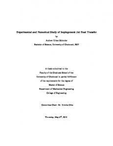
2. Mathematical and Numerical Analysis I. Governing Equations (laminar flow) For flow of air inside the P.C. in Figure 1, laminar (the value of Reynolds number of the air inlet is 2069) 3-D, forced convection, steady, incompressible with Cartesian Coordinates is assumed. The Navier Stokes equations (continuity, momentum and energy) are as follows [7]: Continuity equation ∂ ∂V ∂W (ρu) + (ρv) + (ρw) = 0 ∂x ∂y ∂z
(1)
Momentum equation U-Momentum (x-direction) ∂ ∂ ∂ 1 ∂P (uu) + (uv) + (uw) = − + ∂y ∂2 u ∂2 u (∂x2 + ∂y2
∂z
+
(2)
V-Momentum (y-direction) ∂ ∂ ∂ 1 ∂P (vu) + (vv) + (vw) = − + ∂x
∂y ∂z ∂2 v ∂2 v ∂2 v (∂x2 + ∂y2 + ∂z2 )
ρ ∂y
(3) W-Momentum (z-direction) ∂ ∂ ∂ 1 ∂P (wu) + (wv) + (ww) = − + ∂x ∂y ∂z ρ ∂z ∂2 w
( ∂x2 +
∂2 w ∂2 w + ∂z2 ) ∂y2
(4) Energy equation
Nomenclature
∂x
∂2 u ) ∂z2
ρ ∂x
∂ ∂ ∂ (uT) + (vT) + (wT) ∂x ∂y ∂z ∂2 T ) ∂z2
=
k ∂2 T ∂2 T ( + 2+ ρ Cp ∂x2 ∂y
(5) The transport equations for continuity, momentum and energy all have the general form [9]: ∂ ∂ ∂ (ρu∅) + (ρv∅) + (ρw∅) ∂x ∂y ∂z ∂ ∂∅ ∂ ∂∅ = (Γ∅ ) + (Γ∅ ) ∂x ∂x ∂y ∂y ∂ ∂∅ + (Γ ) ∂z ∅ ∂z + S∅ (6) Where ∅ the dependent variable, and S∅ is the source term which has different expressions for different transport equations. Table (1) gives the expression for the source term S∅ for each dependent variable, which is likely to be needed in solving fluid flow problems. Table 1: Source term in the transport equations for laminar flow Equation Continuity x-momentum y-momentum z-momentum Energy
∅ 1
Γ∅
S∅
0
U
V
W
0 ∂P − ∂x ∂P − ∂Y ∂P − ∂Z
T
𝛼
Where: k 𝛼= ρ Cp II. Steady Heat Conduction The heat transfer within solid PC components is numerically calculated. If the system is in a steady state, then the heat flow in the x, y and z 134
Engineering and Technology Journal
Vol. 36, Part A, No.4, 2018
directions may be calculated from Fourier equation: ∂T q = −kA (7) ∂X Energy balance methods were used and can be described as the summation of heat in and out equals to zero and were applied over small elements, the element has six faces. These elements in heat generation components [9, 10 and 11]: 1. CPU. 2. PSU. 3. Motherboard. For example; node details of motherboard as shown in Figures 2 and 3. The motherboard has (40×48×1) nodes, all these nodes have one face which is insulated and the opposite face has convection except the nodes with the CPU: ∑ q all faces = 0 ∑ q all faces = qe−x + qw−x + qn−y + qs−y + qt−z + qb−z + PMO = 0 (8) Ae = ∆y ∆z , Aw = ∆y ∆z , An = ∆x ∆z , As = ∆x ∆z , At = ∆x ∆y , Ab = ∆x ∆y (9) −k MO Ae qe−x = (TMO(i,j,k) ∆x (10) − TMO(i+1,j,k) ) −k MO Aw qw−x = (TMO(i,j,k) ∆x − TMO(i−1,j,k) ) (11) −k MO An (TMO(i,j,k) ∆y − TMO(i,j+1,k) ) −k MO As qs−y = (TMO(i,j,k) ∆y − TMO(i,j−1,k) ) qt−z = hMO Ab (TMO(i,j,k) − Tair ) qb−z = 0 (insulated) The temperature is given by: qn−y =
(12)
(13) (14) (15)
TMO(i,j,k) = [ Ce TMO(i+1,j,k) + Cw TMO(i−1,j,k) + Cn TMO(i,j+1,k) + Cs TMO(i,j−1,k) + Ct Tair + PMO ] /C (16)
Where: k MO Ae k MO Aw k MO An Ce = , Cw = , Cn = ∆x ∆x ∆y k MO As , Cs = , Ct ∆y = hMO At (17) And
C = Ce +Cw + Cn + Cs +Ct +Cb (18) And i,j,k to represents X,Y,Z respectively, The temperatures of the other components (CPU, Heat sink, PSU) were solved in the same method. The equations solved (by finite volume method CFD) with 1000 iteration at 15 minutes using Fortran 90.
3. Experimental Apparatus The experimental rig was constructed to study the fluid flow and heat transfer in box similar to the computer case. The idea of the study was to find the effect of changing the powers multicomponents (CPU, PSU, and motherboard) and the inlet air velocity with the change air velocity of CPU fan for block heat sink. The photograph of experimental apparatus is shown in Figure 4, which consists of: 1. Pyrex box. 2. Four heaters: one heater used to represent CPU, one heater to represent motherboard and two heaters to represent the front face and lower face of PSU. 3. Heat sink: block heat sink made from copper. 4. Fans. 5. Voltage regulator (Variac). 6. DC power supply: to change the velocity. 7. Measurement units. a. Temperature recorder: it used to measure the temperature of the main components. b. Hot wire anemometer: it used to measure the velocity. c. Digital power clamp meter: it used to measure the power. Experiments were done to measure the temperature change of the three main components (CPU, MO and PSU) of the desktop computer, the temperature of heat sink, temperature of air inside the P.C. and temperature of air inlet and outlet with the change of velocity and experiments to measure the temperatures change with the changing the powers of the three main components. The number of experiments is 15, the measurements to find temperatures using thermocouples were connected from one side to the place that measured its temperature and from other side to temperature recorder. The measurements were drawn and compared with the theoretical readings to find the appropriate temperatures.
4. Results and Discussion I. Experimental Results 1. Effect of Inlet Velocity
132
Engineering and Technology Journal The maximum temperatures of CPU and other components in P.C. obtained at the maximum power for CPU, PSU and motherboard with copper heat sink at minimum inlet air velocity (1.2 m/s) and (T∞ = 33℃) are given in Table 2. Figure 5 illustrates the variation of temperatures of the components with inlet velocity at PCPU = 8.5 W, PPSU =24 W, PMO=12 W. The temperature is decreased with increasing inlet velocity; the slope of the decreasing has same trend for CPU and HS and same trend for PSU1, PSU2 and MO. The temperature of CPU is higher than the others; it varies between 88.1℃ at minimum inlet air velocity 1.2 m/s and 74.1℃ at 2.4 m/s. The MO temperature is the lowest one. It varies between 51.5 ℃ at minimum inlet air velocity 1.2 m/s and 44.8℃ at 2.4 m/s. The temperature range in Fig. 5 was set by limitation maximum allowable temperature (standard operating temperature) for CPU (70℃ to 85℃ ), for MO maximum allowable was 48℃ and 70℃ for PSU. The power of the components in this graph represents the maximum allowable powers to reach the temperature limits. The velocity of CPU fan was chosen in relation to inlet velocity to achieve allowable temperature of CPU. The temperature of PSU depends on the cooling; the lower face temperature is lower than the front face due to the position of this face near the CPU fan and inlet from one side and inlet from another side. The temperature of CPU and power supply faces great affected by the velocity, motherboard temperature and little affected by the velocity of air. From these results and to keep the CPU within allowable temperature limit, the power should be reduced lower than (8.5 W) or by increasing the inlet air velocity and CPU fan velocity, the CPU power varies according to usage and the type of CPU; it starts from 30 W to 130 W. In this research a suitable power was used to reach the temperature of the heater to the standard operating temperature of the CPU. 2. Effect of Power Dissipation Figure 6 shows the variation of temperature of components with CPU power at inlet velocity 1.8 m/s, PPSU =16 W and PMO=8 W. The temperature increased with increasing CPU power. The slope of the increasing has same trend for CPU and HS. In addition, the slope is same trend for PSU1, PSU2 and MO. The temperature of CPU is higher than the others. It varies between 57.3℃ at 3.7 W and 74.1℃ at 8.5 W. MO temperature is the lowest and varies between 41.5℃ and 43.4℃. The temperatures of CPU and HS are greatly affected by the change of the CPU power, while the temperatures of other components are slightly
Vol. 36, Part A, No.4, 2018 affected. The CPU may not dissipate maximum power all the time, this depend on kind of P.C. and the operation. The other components are less sensible to PCPU change; their temperatures increase about two degrees for PSU faces and about one degree in motherboard temperature. Fig. 7 shows the variation of CPU temperature with the variation of inlet air velocity, at PPSU =16 W, PMO=8 W for different powers of CPU. The CPU temperature increases with increases of the power and decreases with increases of the velocity of inlet air. The higher CPU temperature was 83.4℃ at the power equals to 8.5 W and velocity of 1.2 m/s, the lowest CPU temperature was 54.2℃ at the power equal to 3.7 W and velocity equals to 2.4 m/s. These temperatures decrease with the power and velocity as shown in Table 3. Fig. 8 shows the variation of CPU temperature with the variation of inlet air velocity at PCPU=8.5 W for different powers of MO and PSU. The slopes of temperatures have the same trend. The higher temperature of CPU is 88.1℃ at PPSU =24 W, PMO=12 W and 1.2 m/s, the lower temperature equal to 68 at PPSU =8 W, PMO=4 W and 2.4 m/s. From Figures 7 and 8, it appears that the temperature of CPU is affected by the change of CPU power greater than by the change in MO and PSU powers. Table 2: Maximum temperatures of CPU and other components
Component CPU Heat sink PSU front face PSU lower face Motherboard
Maximum temperature (℃ ) 88.1 70 75.6 70.1 51.5
Table 3: CPU temperature variation with PCPU and inlet air velocity
Inlet air velocity (m/s) 1.2 1.8 2.4
Temperatures (℃ )
8.5 W 83.4 74.1 69.8
6.1 W 74.1 66.9 62.9
3.7 W 62.2 57.3 54.2
II. Numerical Results 1. Effect of Inlet Velocity Figure 9 shows the variation of temperatures with the variation of inlet air velocity at PCPU =8.5 W, PPSU=24 W, PMO=12 W. The temperature 133
Engineering and Technology Journal decreases with increasing of inlet velocity, the slopes of decreasing have the same trend for CPU and HS and same trend for PSU1, PSU2 and MO. The temperature of CPU is higher than the others. It varies between 85.23℃ at minimum inlet air velocity 1.2 m/s to 79.18℃ at 2.4 m/s. The MO temperature is the lowest one, it varies between 54.4 ℃ at minimum inlet air velocity 1.2 m/s to 48.27℃ at 2.4 m/s. 2. Effect of Power Dissipation Figure 10 shows the variation of temperatures with CPU power at PPSU =16 W, PMO=8 W, inlet velocity 1.8 m/s and WCPU=3 m/s. The temperature increased with increasing CPU power, the slope of increasing has the same trend for CPU and HS and the slope was same trend for PSU1, PSU2 (front face and lower face of power supply respectively) and MO. III. Isothermal Distribution in P.C. Figure 13 illustrates 3D plots of the isothermal contours with different directions at PCPU = 8.5 W, PPSU = 24 W, PMO =12 W, Vin = Uin = 1.2 m/s, WCPU = 2 m/s, (a) 3D, (b) CPU at z = 20 cm, (c) block heat sink at z =15 cm, (d) motherboard at z = 20 cm, (e) PSU1 at x = 26 cm, (f) PSU2 at y = 31 cm. the three dimensional plot shows the temperature distribution inside the box. To show the details of temperatures in the domain, a 2d surface plots are used. In b, z = 20 cm, the red area shows the highest temperature of CPU. The internal area of the CPU temperature is nearly 85℃. In c, the HS temperature was nearly 69℃. In d, the motherboard temperature at z = 20 cm, the temperature close to 50℃ , it increased in area of CPU and decreased near the position of outlet. In e and f, the two faces of power supply were shown. IV. Flow Field Distribution Fig. 14 shows the flow field in PC at PCPU=8.5 W, PPSU =24 W, PMO=12 W, Vin = Uin = 1.2 m/s, WCPU =2 m/s. The figure shows the outlet openings at y = x = 0.2 m. In b, the figure shows the flow field at z = 0.1 (high processor fan velocities). In c, four x surfaces are shown; the white areas represent the positions of HDD, CD and PSU. In d, four levels of y are shown, in the third level, the fan velocities against the processor are clear. V. Comparison between numerical and experimental results Figures 11 and 12 show the comparison between numerical and experimental results for distribution of surface temperature with inlet air velocity of CPU and MO at PCPU =8.5 W,
Vol. 36, Part A, No.4, 2018 PPSU=24 W, PMO=12 W. A good agreement is shown between the numerical and experimental results and it can be observed that both numerical and experimental results have the same behavior. It was found that the numerical results are greater than the experimental results.
5. Conclusions The conclusions that can be drawn from the present study are: 1. The temperature of the heat generation components decreases linearly with increases of inlet air velocity. 2. The CPU temperature increases with CPU power linearly. 3. The temperatures of other components affected little by CPU power. 4. The CPU temperature is slightly affected by the power of other components. 5. PSU2 temperature was less than the PSU1 temperature due to its position close to inlet, outlet CPU fan. 6. Motherboard temperature was the lowest one due to its position and large area.
Figure 1: PC case
131
Engineering and Technology Journal
Vol. 36, Part A, No.4, 2018 90 CPU HS PSU1 PSU2 MO
Surface temperature ( C)
80
o
70
60
50
40
30
1
1.5
Inlet air velocity (m/s)
2
2.5
Figure 5: Variation of temperatures with inlet air velocity at PCPU = 8.5 W, PPSU = 24 W, PMO = 12 W 75
Figure 2: Motherboard Node
CPU HS PSU1 PSU2 MO
70
Surface temperature ( C)
65 o
60 55 50 45 40 35 30
Figure 3: Energy balance for nodes on motherboard
3
4
5
6
CPU power (W)
7
8
9
Figure 6: Variation of temperatures with CPU power at PPSU = 16 W, PMO = 8 W, inlet velocity 1.8 m/s and WCPU = 3 m/s 90
CPU temperature ( C)
80
o
70
60
50
Pcpu=8.5 W Pcpu=6.1 W Pcpu=3.7 W
40
30
Figure 4: Photograph of experimental apparatus
1
1.5
Inlet air velocity (m/s)
2
2.5
Figure 7: Variation of CPU temperature with inlet air velocity, at PPSU =16 W, PMO = 8 W
134
Engineering and Technology Journal
Vol. 36, Part A, No.4, 2018 80
90
CPU HS PSU1 PSU2 MO
75 70
o
Surface temperature ( C)
CPU temperature ( C)
80 o
70
60
50
60 55 50 45 40
Ppsu=24 W, Pmo=12 W Ppsu=16 W, Pmo=8 W Ppsu=8 W, Pmo=4 W
40
65
35 30
1.5
1
Inlet air velocity (m/s)
2.5
2
Figure 8: Variation of CPU temperature with inlet air velocity, at PCPU = 8.5 W
3
4
5
6
CPU power (W)
7
8
9
Figure 10: Variation of temperatures with CPU power at PPSU = 16 W, PMO = 8 W, inlet velocity 1.8 m/s and WCPU = 3 m/s 100
90
90
o
80
Surface temperature ( C)
Surface temperature ( C)
80 o
70
60
50 CPU HS PSU1 PSU2 MO
40
70 60 50 40 30
10 0
30
Numerical Experimental
20
1
1.5
Inlet air velocity (m/s)
2
1
1.5
Inlet air velocity (m/s)
2.5
Figure 9: Variation of temperatures with inlet air velocity at PCPU = 8.5 W, PPSU = 24 W, PMO = 12 W
2
2.5
Figure 11: Comparison between numerical and experimental results for surface temperature with inlet air velocity of CPU at PCPU = 8.5 W, PPSU = 24 W, PMO = 12 W
100 90
Surface temperature ( C)
80 o
70 60 50 40 30
Numerical Experimental
20 10 0
1
1.5
Inlet air velocity (m/s)
2
2.5
Figure 12: Comparison between numerical and experimental results for surface temperature with inlet air velocity of MO at PCPU = 8.5 W, PPSU = 24 W, PMO = 12 W
134
Engineering and Technology Journal
Vol. 36, Part A, No.4, 2018
0.4 0.4
0.4
0.3
0.3
0.3
0.1
Y (m)
Y (m)
Y (m)
0.2 0.2
0.2
0.1
0.1 0 0.05 0
0.1
0.2
m) X( 0.2
0.15
Z(
(a)
0
0.15
0.25 0.1
0.3
m)
0
0
(b)
0.4
0
0.1
0.2
0.35
0.05
Z(
0.1
m)
0.3
m) X(
0.3
) X (m
0.2
0.15
(c)
Z(
0.1
m)
0.05
Z ( m 0.1 )
0.05
0.05 0.4
0
0.3
0.2
m) X( 0.2
0.15
0
0.4
0
0.4
Y
T ( o C)
Y (m)
0.2
0.1
0.4
0.3
0.3
Y (m)
0.3
X
0.4
Y (m)
85 78.5 72 65.5 59 52.5 46 39.5 33
0.4
Z
0.2
0.2
0.1
0.1
0 0 0.1
0
0
m) X(
0.2
(d)
0.2
0.15
Z(
0.1
m)
0.3 0.05 0
0
0.1
) X (m 0.2
0.2
(e) (e)
0.15
Z (m
0.3
0.1
0.4
)
0.05
(f)
0.4
0
0.2
0.2
0.15
Figure 13: Isothermal distribution at PCPU = 8.5 W, PPSU = 24 W, PMO=12 W, Vin = Uin = 1.2 m/s, WCPU = 2 m/s, (a) 3D, (b) CPU z = 20 cm, (c) block heat sink z = 15 cm, (d) motherboard z = 20 cm, (e) PSU1 x = 26 cm, (f) PSU2 y = 31cm (3D) 04 Apr 2017
(3D) 04 Apr 2017
Y
Y
Z
Z
X
X
0.4
0.4 0.3 0.2
0.2
0.1 0
0 0.1
0 0.2
0.2
a
0.3
0.1 0
0.1
0 0.2
0.2 0
0.4
(3D) 04 Apr 2017
b
0.3
0.1 0.4
(3D) 04 Apr 2017
Y
Y
Z
Z
X
X
0.4
0.4 0.3 0.2
0.2
0.1 0
0 0.1
0 0.2
0.2 0.3
0.1 0
0.4
c
0.1
0 0.2
0.2
d
0.3
0.1 0
0.4
Figure 14: Flow field in PC (PCPU = 8.5 W, PPSU = 24 W, PMO = 12 W, Vin = Uin = 1.2 m/s, WCPU = 2 m/s), a) outlet openings, b) z = 0.1 m, c) different x surfaces, d) different y levels
134
Engineering and Technology Journal
Vol. 36, Part A, No.4, 2018
References [1] M. Anandakrishnan and C. Balaji, “CFD Simulations of Thermal and Flow Fields inside a Desktop Personal Computer Cabin with Multi-Core Processors,” Engineering Applications of Computational Fluid Mechanics, Vol.3 No.2 pp.277288, 2009. [2] J.Y. Chang, C.W. Yu, and R.L. Webb, “Identification of Minimum Air Flow Design for a Desktop Computer Using CFD Modeling,” Department of Mechanical and Nuclear Engineering, The Pennsylvania State University, University Park, PA 16802-1413, pp.330-338, 2000. [3] E. Ozturk and I. Tari, “Forced Air Cooling of CPUs with Heat Sinks: A Numerical Study,” IEEE Transactions on Components and Packaging Technologies, Vol. 31, No. 3, September 2008. [4] R. Mohan and P. Govindarajan, “Thermal Analysis of CPU with Variable Heat Sink Base Plate Thickness using CFD,” International Journal of the Computer, the Internet and Management, Vol. 18, No.1 , pp. 2736, 2010. [5] S.K. Wang, J.H.Hu and C.H. Kuo, “Passive Enhancement of Heat Dissipation of Desktop computer Chassis,” Engineering Applacations of Compotational Fluid Dynamics, Vol. 4, No.1, pp.139149, 2010. [6] L. Maode, Q. Cong and Z. Zhisong, “Numerical Analysis of Temperature Field on the Desktop Computer Motherboard,” Applied Mechanics and Materials Vols. 644-650, pp.1531-1534, 2014.
Author biography Prof. Dr. Jalal M. Jalil, University of Technology, Baghdad, Iraq, Electromechanical Eng. Dept. Born in Iraq on 23th November 1958, Completed Bachelor of Engineering (Mechanical Engineering) in the year of 1980 and completed Master and PH.D of Engineering (Thermal Engineering) in the year of 1984 and 1988. His research area is CFD and heat transfer. E-mail:
[email protected] Asst. prof. Ekbal H. Ali, University of Technology, Baghdad, Iraq, Electromechanical Eng. Dept. Born in Iraq 1973, she completed B.sc, M.sc and PH.D degree in Electrical Engineering in the year of 1995, 2001 and 2007. Her research area are computer and navigation system. Hiba H. Kurdi was born in Baghdad, Iraq, in 1991. She received B.Sc. and M.Sc. degrees in Electromechanical Engineering /power branch from the Department of Electromechanical Engineering, University of Technology, Iraq in 2013 and 2017, respectively. Her publications interests is heat transfer. E-mail:
[email protected]
[7] H. B. Awbi, “Ventilation of Buildings,” London, 2003. [8] H. Versteeg, and W. Malalsekera, “An Introduction to Computational Fluid Dynamics-The Finite Volume Method,” Longman group Ltd., 1996. [9] B.K. Dutta “Heat Transfer, Principles and Applications,” Prentice Hall of India 2006. [10] J. P. Holman, “Heat Transfer,” McGraw-Hill, Inc. 2004. [11] G.E. Myers, “Analytical Methods in Conduction Heat Transfer,” McGraw-Hill, Inc., 1971.
134