Progress In Electromagnetics Research M, Vol. 14, 247–261, 2010
NUMERICAL EVALUATION OF THE MAGNETIC FIELD EXPOSURE NEAR THE TRANSITION TOWER OF AN OVERHEAD-UNDERGROUND HV LINE W. Krajewski Institute of Electrical Engineering Po˙zaryskiego 28, Warsaw 04-703, Poland Abstract—The paper deals with the analysis of the magnetic field distribution near the transition tower of an overhead-underground transmission line of 110 kV. The current density induced in the human body due to this field is also estimated. A hybrid numerical technique combining both the boundary element method and the charge simulation method is employed for this purpose. This technique is implemented in the author’s own software package dedicated to the analysis of electromagnetic exposure in the vicinity of power objects. A simplified numerical model of the human body of dimensions recommended by the IEC/EN standards is employed in computations. Obtained numerical results are related to the appropriate regulations regarding the human exposure to the electromagnetic fields. 1. INTRODUCTION Overhead HV lines are sources of the electric and magnetic fields of low frequency (50/60 Hz). Near the ground surface, these fields cannot exceed values determined by ecological and health regulations or EMC standards. According to the above regulations, the considered fields should be estimated during the HV line designing. In the literature, there are many papers, e.g., [1–10] devoted to the electric and magnetic field assessment in the vicinity of overhead HV lines. In these works, analytical methods [10] as well as numerical ones [1–9] are employed for this purpose. Nowadays, there are also commercial software packages, e.g., EFC-400 [11] (worked out by Narda), dedicated to estimate the electric and magnetic fields under HV lines. In general, the problem of the electromagnetic emission of these power objects is rather well Received 11 October 2010, Accepted 28 October 2010, Scheduled 11 November 2010 Corresponding author: Wojciech Krajewski (
[email protected]).
248
Krajewski
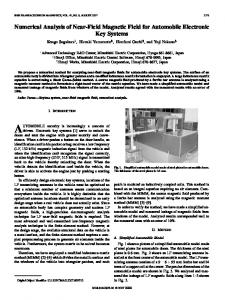
recognized from the theoretical (computations) as well as practical (measurements) point of view. Nevertheless, in practise, there are some particular problems that are not deeply analysed and discussed in the literature as yet. One of them is an estimation of the electromagnetic exposure near the HV tower on which a transition from an overhead line to an underground cable line takes place (Fig. 1). In this case, insulated phase conductors are leaded vertically along the tower height and they are connected with a three-phase cable under the ground surface. People staying near such a tower can be exposed to the electric and magnetic field of higher strength than in the case of conventional overhead lines. These hybrid (overhead-underground) HV lines are recently applied in great cities, to transmit the electric energy to central districts of these cities to supply large commercial buildings of a great demand for the electric energy. The electric field emission from the considered tower was earlier analysed by the author and obtained results will be published in detail in the future article. In the present paper, the computational results of the magnetic field distribution near such a tower are exhibited. Moreover, eddy currents induced in the human body due to this field are also analysed. According to the guidelines of the International Commission on Non-Ionizing Radiation Protection (ICNIRP) [12], the density of these currents in the human body cannot exceed 2 mA/m2 in the case of general public exposure. A hybrid numerical technique combining the boundary element method (BEM) [13] and the charge simulation method (CSM) [14] is employed to solve the problem in question. It was shown in previous author’s works [7, 8, 16] that this approach is particularly suitable for the numerical modelling of fields emitted by power objects.
Figure 1. Transition towers of 110 kV overhead-underground transmission lines.
Progress In Electromagnetics Research M, Vol. 14, 2010
249
2. MATHEMATICAL FORMULATIONS In this section, general assumptions of the mathematical model of the magnetic field near the ground surface in the neighbourhood of the transition tower of the hybrid overhead-underground line are presented. A boundary-integral model of eddy-currents induced within the human body due to the external magnetic field is also shortly described. Basic integral equations governing these problems are formulated. In the case of conventional overhead HV lines, the influence of tower frameworks on the magnetic field distribution is negligible on the contrary to their strong influence on the electric field distribution. This fact has been corroborated experimentally by earlier author’s investigation [8]. The mentioned effect can be accounted for by a relatively small value of the magnetic field strength near truss angle bars. In this case, the relative magnetic permeability of these steel elements is approximately equal to 1. On the other hand, some vertical cables of the transition tower are located closely to the tower truss, therefore, the magnetic field strength can reach considerable values around some angle bars of the tower. According to the above remarks, the influence of these steel elements should be taken into account in the analysis of the problem under consideration. In the proposed numerical model, the elements of the tower framework are represented by internally located fictitious line magnetic charges. The magnetic scalar potential is equal to a constant value on the surfaces of these elements. These assumptions lead to the CSM formulation for the ideal ferromagnetic object. Conducting, nonmagnetic solid objects (e.g., human body) are represented by fictitious surface magnetic charges and fictitious surface currents. This assumption leads to the indirect version of the BEM for eddy-current problems, which was theoretically formulated by Mayergoytz in [15]. The currents in live conductors excite the primary magnetic field, which is computed from the Biot-Savart law: Z Iex r(P, Pi ) × dl H0 (Pi ) = − (1) 4π r3 Kex
where: r is the distance between integration point P , and observation point Pi , Kex is the curve representing excitation current Iex . In the eddy-current subregion, which means here the human body, the magnetic field strength fulfils the following Helmholtz equation of the vector type: ∆H − iωγµH = 0 (2)
250
Krajewski
where: i — imaginary unit, ω — angular frequency, γ — conductivity, µ — magnetic permeability. In the air subregion, i.e., outside the human body and tower truss, the scalar potential of secondary magnetic field is governed by the Laplace equation: ∆ψm = 0
(3)
Continuity conditions on interface ΓI between the eddy-current subregion and the air resulting from the continuity of the normal component of the magnetic flux density and from the continuity of tangential component of the magnetic field strength are as follows: n · µ0 (H0 − gradψm )|ΓaI = n · µec H|Γec I n × µ0 (H0 − gradψm )|ΓaI = n × H|Γec I
(4) (5)
Superscripts a and ec indicate that the value of the considered quantity belongs to the air or to the eddy-current subregion, respectively. The boundary condition on the surface of the tower framework (ideal ferromagnetic body) is: ψ|Γf = C
(6)
where C is an unknown constant value. The total magnetic scalar potential outside the current subregions can be expressed as superposition of the primary and secondary potentials: ψ = ψ0 + ψm
(7)
The scalar potential of the primary magnetic field (derived as a line integral of H0 ) is given below: Iex ψ0 (Pi ) = 4π
ZPi Z
r(P, Pi ) × d l1 ·dl2 r3
(8)
P0 Kex
P0 is a chosen point of the air space. The path of integration from point P0 to Pi cannot cross the surface of potential discontinuity. It means that this path cannot surround any source currents. In practical problems, the compact subregion that does not surround the source currents but contains the all problem boundaries and P0 can be, in general, selected. If the integration path belongs to such a subregion the discontinuity of the scalar potential of the primary magnetic field does not appear. The magnetic field strength in the eddy-current subregion can be expressed as follows: Z H(Pi ) = curli [GH (P, Pi )js (P )]dP (9) ΓI
Progress In Electromagnetics Research M, Vol. 14, 2010
251
where js (P ) denotes the fictitious surface current density. GH (P, Pi ) is the fundamental solution for the 3D Helmholtz equation: 1 −iβr GH (P, P i ) = e (10) 4πr where: β 2 = −iωrµ. The scalar potential of the secondary magnetic field can be expressed in the following form: Z Z ψm (Pi ) = GL (P, Pi )σm (P )dP + GL (P, Pi )τm (P )dP (11) ΓI
Kf
where σ m (P ) and τ m (P ) are the fictitious magnetic surface and line charges, respectively. Kf is the curve representing the tower truss. GL (P, Pi ) is the fundamental solution for the 3D Laplace equation: 1 GL (P, P i ) = (12) 4πr Applying the well-known relationships of the vector calculus and the formula for the normal derivative of the single-layer potential and yet continuity conditions (4) and (5), the set of two boundary integral equations can be formulated: Z 1 js (Pi ) + ni × [js (P ) × gradi GH (P, Pi )]dP 2 ΓI Z Z − ni × gradi GL (P, Pi )σm (P )]dP − ni × gradi GL (P, Pi )τm (P )]dP ΓI
Kf
= −ni × H0 (Pi ) for Pi ∈ ΓI (13) Z 1 σm (Pi ) − ni · gradi GL (P, Pi )σm (P )dP 2 ΓI Z Z − ni · gradi GL (P, Pi )τm (P )dP + ni · [js (P ) × gradi GH (P, Pi )]dP Kf
ΓI
= −ni · H0 (Pi ) for Pi ∈ ΓI Z Z GL (P, Pi )σm (P )dP + GL (P, Pi )τm (P )dP − C ΓI
Kf
= − ψ0 (Pi ) for Pi ∈ ΓKf Z τm (P ) dP = 0 Kf
(14)
(15) (16)
252
Krajewski
ΓKj denotes the surface of tower truss elements. Equation (16) resulting from the so-called magnetic Gauss law is introduced to obtain the unique solution of the problem because C is of unknown value. The set of the above integral equations is the basis for the hybrid the BEM and CSM approach to the problem under consideration. These integral equations are transformed into a set of algebraic ones. For this purpose, the subregion boundaries as well as lines representing the tower framework are subdivided into a finite number of surface and line elements, on which the unknown functions: js , σ m , and τ m (P ) are approximated. After determining the surface densities of fictitious current, js , and magnetic charges: σ m and τ m (P ) (by the numerical solution of the set of algebraic equations), the magnetic field strength can be computed anywhere within the eddy-current region and in the air using formulas: Z H(Pi ) = − js (P ) × gradGH (P, Pi ) dP (17) ΓI
Z
H(Pi ) = −
gradi GL (P, Pi ) σm (P )dP ΓI
Z
−
gradi GL (P, Pi )τm (P )dP + H0 (Pi )
(18)
Kf
Obviously, if the conductivity of eddy-current region is of small value, as it is in the case of human body, it can be approximated by: H(Pi ) ≈ H0 (Pi ) (19) Generally, the eddy-current density can be computed using formula: j(Pi ) = curl H(Pi ) (20) where H(Pi ) denotes the magnetic field strength calculated by (17). If the subregion of eddy currents and excitation current are separated each other, the eddy-current density can be computed as follows: Z j(Pi ) = −iωγµ GH (P, Pi )js (P )dP (21) ΓI
More details concerning this method are presented in [16] by the author. 3. GEOMETRY OF THE HUMAN BODY MODEL In the literature, there are numerous papers, e.g., [17–20], devoted to computations of the eddy currents induced in the human body due
Progress In Electromagnetics Research M, Vol. 14, 2010
253
to the external magnetic field. Realistic anatomical models of the human organism [17–19] are very useful for investigations of biological effects. On the other hand the simplified models [20] are rather more appropriate for dosimetry studies as well as for the analysis of practical problems regarding the human exposure to the electromagnetic fields. An axisymmetric homogeneous numerical model of the human body is employed in the present paper. This model is recommended by the appropriate IEC/EN standards, e.g., IEC/EN 62233 [20]. Basic dimensions of the considered model are presented in Fig. 2, where a subdivision of this object is also exhibited. The finite element implementation of this human body representation is described in [21]. In the present paper, the described earlier, indirect BEM approach is employed for the numerical analysis. In further numerical examples, the considered body model is situated 0.2 m over the ground surface as it is shown in Fig. 2. 4. ANALYTICAL VALIDATION OF NUMERICAL RESULTS The eddy-current distribution in the human body is not directly measurable; therefore, the analytical solution is employed to validate the numerical technique under consideration. The problem of eddy currents induced by a homogeneous magnetic field is considered for this purpose. The strength of this field is parallel to the axis of the human-body model. When the conductivity of eddycurrent region is of small value, as it is in the case of human body,
Figure 2. Numerical model of human body.
254
Krajewski
the current density is given by the following formula derived from the Faraday’s law of induction: j(r) ≈ 0.5 ωµ0 γrH0
(22)
It is assumed in the examples presented below that: H0 = 400 A/m and γ = 0.2 S/m. The boundary of the human-body model is subdivided into 1344 boundary elements. The current-density distribution at the levels of 1 m and 1.6 m are plotted in Figs. 3 and 5, respectively. A relative error of numerical result is defined as follows: ¯ ¯ ¯ jn (r) − ja (r) ¯ ¯ ¯ · 100% error j(r) = ¯ (23) ¯ ja (r) where subscripts n and a denote numerical and analytical results, respectively. The error distributions are presented in Figs. 4 and 6. Good accuracy of the numerical results corroborates the effectiveness of the applied numerical technique and the correctness of the worked out computer code. It is worth to state that the simple formula (22) for the evaluation of currents induced in the human body is valid only in the case of homogeneous primary magnetic field and it is useless when this field is strongly inhomogeneous. In the further examples, the primary magnetic field is strongly inhomogeneous; therefore, the numerical technique has to be employed in this case.
Figure 3. Distribution of the induced current density within the model of the human body at the level of 1 m (trunk); continuous line — numerical results, dash line — analytical results.
Progress In Electromagnetics Research M, Vol. 14, 2010
255
Figure 4. Relative error of the numerical results of the induced current density within the model of the human body at the level of 1 m (trunk).
Figure 5. Distribution of the induced current density within the model of the human body at the level of 1.6 m (head); continuous line — numerical results, dash line — analytical results. 5. NUMERICAL EVALUATION OF THE MAGNETIC FIELD EXPOSURE In this section, the magnetic field distribution in the vicinity of the transition tower of 110 kV line of two circuits is analysed. Moreover, computational results of eddy currents induced due to this field inside the numerical model of the human body are presented. The author’s own software package BEMsolver 3D is employed for these computations.
256
Krajewski
Figure 6. Relative error of the numerical results of the induced current density within the model of the human body at the level of 1.6 m (head). As it was mentioned earlier, the considered transition tower is equipped with vertical cabling which connects overhead conductors with the underground three phase 110 kV cable. The influence of this underground cable on the magnetic field over the ground surface is rather negligible because of three-phase compensation of this field and also because of its relatively deep location (about 2.5 m). A special metal casing of 5 m height is applied to protect the vertical cabling system against a mechanical damage. Unfortunately, this casing almost does not dampen the magnetic field; therefore, the vertical cabling is the main source of the magnetic field near ground surface. The approximation of the considered tower with the line-element mesh is exhibited in Fig. 7, where the numerical model of human body located near this tower is also presented. In computations, the tower truss has been approximated by 428 line elements and the surface of human body model has been divided into 1344 boundary elements as in the previous section. The above problem is described by 8920 algebraic equations. The total solution time (including time of discretization, calculation of coefficients of equation system, solution of equation system an calculating of magnetic field strength for a considered domain) on a Intel Core 2 Duo, T7600 2.33 GHz computer with 4 GB RAM is about 3 hours. Distributions of the magnetic field strength near the HV tower at the levels of 1 and 2 m over the ground surface are presented in Figs. 7
Progress In Electromagnetics Research M, Vol. 14, 2010
(a)
257
(b)
Figure 7. Numerical model of the transition tower of 110 kV line. (a) General view, (b) horizontal projection.
(a)
(b)
Figure 8. Distribution of the magnetic field strength near the transition tower of 110 kV line. (a) 1 m over the ground surface, (b) 2 m over the ground surface. and 8, respectively. In the computations, the HV line current of 500 A has been assumed. The calculated magnetic field strength reaches 280 A/m and 250 A/m at the levels of 1 m and 2 m, respectively. These values appear at the surface of the vertical cable casing (in a distance of 2.5 m from the tower centre). Measurements taken by the author closely to the real tower corroborate the above numerical results. Polish environment protection regulations determine the allowable values of electromagnetic fields in public domain. According to these regulations, the strength of the magnetic field of 50 Hz cannot exceed 60 A/m; however, the relevant European recommendation [22] allows
258
Krajewski
(a)
(b)
Figure 9. Distribution of the current density in the model of the human body. (a) In the cross-section perpendicular to the HV line axis. (b) In the cross-section parallel to the HV line axis. 2
2
1.8
1.8
1.6
1.6
1.4
1.4 1.2 1.6
1
1.5 1.4 1.3 1.2
0.8
1.1
z (m)
z (m)
1.2
1
2.2 2 1.8
0.8
1.6
1
1.4
0.9
0.6
0.8 0.7
0.6
1.2 1
0.6 0.5
0.4
0.4
0.8
0.4
0.6
0.3
0.4
0.2
0.2 0
0.1 0.01
-0.4 -0.2 0
x (m)
0.2 0.4
0.2
0.2 0.01
0 2.2 2.4 2.6 2.8 3
3.2
y (m)
Figure 10. Lines of current density in the model of the human body in the cross-sections: perpendicular (left) and parallel (right) to the HV line axis; current density is expressed in mA/m2 . 80 A/m in this case. Nevertheless, in the analysed example, the both values are exceeded. According to the ICNIRP guidelines [12] mentioned in the introduction, a basic exposure restriction for the magnetic field of 50 Hz is the density of the current induced in the human body due to this field. This restriction prevents effects on human nervous system
Progress In Electromagnetics Research M, Vol. 14, 2010
259
functions. The mentioned current density cannot exceed 2 mA/m2 for the general public exposure. This current density should be estimated to ensure that the above condition is not exceeded. Unfortunately, this quantity is not directly measurable; therefore it has to be evaluated computationally. In the consecutive numerical example, the eddy-current density in the human body model is analysed. This model is located (as it is shown in Fig. 7) in the distance of about 0.5 m from the vertical tower cables. The computations have been performed for two crosssections of the human body model: perpendicular and parallel to the transmission line axis. Numerical results are exhibited in Figs. 9 and 10. They show that the current density exceeds 2 mA/m2 in the crosssection parallel to the HV line axis. The above examples indicate that the transition tower can emit the magnetic field of significant strength near the ground surface. This field should be estimated during the tower designing. It is well known from the theory and practice that it is very difficult to shield the magnetic field of low frequency. Nevertheless, some simple measures can be applied to avoid the transgression of the afore-mentioned restrictions. One of them is to lead the vertical cables closely (as it is possible) one to each other for the better three-phase compensation of the magnetic field. Another measure is to fence the tower to keep people in an enough distance from the vertical cables. Unfortunately, such a solution is not always possible. The similar solution is to enlarge the vertical cable casing. 6. CONCLUSION The human exposure to the magnetic field of 50 Hz near the transition tower of the 110 kV overhead-underground line was investigated. The hybrid numerical technique combining the BEM and CSM was employed for this purpose. The numerical results indicate that the tower vertical cabling can emit near the ground surface the magnetic field of significant strength. The density of currents induced within the human body due to this field can exceed the value admissible by ICNIRP. The simple measures have been proposed to limit the people exposure to the magnetic field near the HV tower under consideration. REFERENCES 1. Isaka, K., et al., “Characterisation of electric and magnetic field at ground level under EHV transmission lines,” 7th International Symposium on High Voltage Engineering, 51–54, Dresden, 1991.
260
Krajewski
2. Florkowska, B., J. FurgaÃl, W. Nowak, and R. WÃlodek, “Modelling of electric state in the space surrounding high voltage overhead lines,” 9th International Symposium on High Voltage Engineering, 8369-1–8369-4, Graz, Aug. 1995. 3. Maruti, R., K. M. Srinivasa, M. Kanyakumari, E. M. Kumar, and D. R. Channakeshava, “Electric and magnetic field around AC transmission lines and substations,” 9th International Symposdium on High Voltage Engineering, 8350-1–8350-4, Graz, 1995. 4. Hameyer, K. and R. Belmans, “Computation of the electric and magnetic field below high-voltage lines,” 8th International Symposium on Theoretical Electrical Engineering, 278–281, Thessaloniki, Sep. 22–23, 1995. 5. Krajewski, W., “Boundary element approach to the electric and magnetic field analysis in the vicinity of HV transmission lines,” Archiv f¨ ur Elektrotechnik, No. 6, 365–372, 1995. 6. Krajewski, W., “BEM analysis of electric field excited by overhead HV lines erected in built-up areas,” IEE Proceedings — Science, Measurement & Technology, Vol. 144, No. 2, 81–86, 1997. 7. Krajewski, W., “3-D model of the electric field excited by overhead HV lines,” Archiv f¨ ur Elektrotechnik, No. 1, 55–63, 1998. 8. Krajewski, W., “Boundary and line elements in the analysis of selected EMC problems of low frequency,” Prace Instytut Elektrotechniki, 224, 2005 (Monograph in Polish). 9. Trlep, M., A. Hamler, M. Jesenik, and B. Stumberger, “Electric field distribution under transmission lines dependent on ground surface,” IEEE Trans. on Magnetics, Vol. 45, No. 3, 1748–1751, 2009. 10. Tzinevrakis. A. E., D. K. Tsanakas, and E. I. Mimos, “Analytical calculation of electric field produced by single-circuit power lines,” IEEE Trans. on Power Delivery, Vol. 23, No. 3, 1495–1505, 2008. 11. “Simulation software for calculating fields caused by power lines (EFC-400) and on transformer stations (EFC-400ST),” www.narda-sts.de. 12. International Commission on Non-Ionizing Radiation Protection, “Guidelines for limiting exposure to time-varing electric, magnetic, and electromagnetic fields,” Health Physics, Vol. 74, No. 4, 494–521, 1998. 13. Brebbia, C. A., The Boundary Element Method for Engineers, Pentech Press, London, 1978. 14. Singer, H., H. Steinbigler, and P. Weiss, “A charge simulation
Progress In Electromagnetics Research M, Vol. 14, 2010
15.
16.
17. 18. 19.
20.
21.
22.
261
method for the calculation of high voltage fields,” IEEE Trans. on Power Apparatus and Systems, Vol. 93, 1660–1668, 1973. Mayergoytz, I. D., “Boundary integral equations of minimum order for the calculation of three dimensinal eddy current problems,” IEEE Trans. on Magnetics, Vol. 17, No. 2, 536–539, 1982. Krajewski, W., “BEM analysis of 3D EMC problem with consideration of eddy-current effects,” IEE Proceedings — Science, Measurement & Technology, Vol. 153, No. 3, 101–107, 2006. Stuchly, M. A. and S. Zhao, “Magnetic field-induced currents in human body in proximity of power lines,” IEEE Trans. on Power Delivery, Vol. 11, No. 1, 102–108, 1996. Dawson, D., K. Caputa, and M. Stuchly, “Magnetic field exposure for UK live-line workers,” Phys. Med. Biol., Vol. 47, 995–1012, 2002. Cherubini, E., N. Chavannes, and N. Kuster, “Realistic skeleton based Deformation of high-resolution anatomical human models for electromagnetic simulation,” The 31st Annual Meeting of the Bioelectromagnetic Society, 2009 IEC/EN 62233, “Measurement methods for electromagnetic fields of household appliances and similar apparatus with regard to human exposure,” International Electrotechnical Commission, Geneva, 2005. Nishizawa, S., F. Landstorfer, and O. Hashimoto, “Dosimetric study of induction heater using the coil source model prescribed by EN50366,” Proc. 3rd International Workshop on Biological Effects of Electromagnetic Fields, Vol. 2, 894–903, Oct. 2004. 1999/519/EC, “Council Recommendation of 12 July 1999 on the limitation of exposure of the general public to electromagnetic fields (0 Hz to 300 GHz),” Official Journal of the European Communities, L 199, 59–70, Jul. 30, 1999.