for all sections inside the cavity with increasing Richardson number. .... J.L. Wright, H. Jim, ... dimensional cavity for very small Richardson numbers; and it.
Proceedings of the ASME 2015 Power Conference POWER2015 June 28-July 2, 2015, San Diego, California
POWER2015-49575 NUMERICAL INVESTIGATION OF A THREE-DIMENSIONAL LAMINAR MIXED CONVECTION FLOWS IN LID-DRIVEN CAVITY FOR VERY SMALL RICHARDSON NUMBERS M.M. Abo Elazm College of Engineering and Technology, Arab AASTMT-Academy for Science, Technology and Maritime Transport, Alexandria, Egypt
A.I. Shahata College of Engineering and Technology, Arab AASTMT-Academy for Science, Technology and Maritime Transport, Alexandria, Egypt
A.F. Elsafty College of Engineering and Technology AUM- American University of The Middle East, Egaila, Kuwait
M.A. Teamahi Faulty of Engineering, Alexandria University, Alexandria, Egypt
ABSTRACT Laminar mixed convection in a three-dimensional lid driven cavity is numerically investigated. The top lid of the cavity is moving rightwards with a constant speed at a cold temperature. The bottom wall is maintained at an isothermal hot temperature, while the other vertical walls of the cavity are assumed to be insulated. In this study the mass diffusion was not taken into account and the fluid used was air. The flow and heat transfer behavior is studied for various Richardson number ranging from 5 × 10⁻⁵ to 3 × 10⁻⁴ at a fixed Prandtl number of 0.71 through analyzing the local Nusselt number distribution at different sections inside the cavity. Lewis number Le is assumed to be unity and the buoyancy ratio parameter N is equal to zero. Computations were done using an in-house code based on a finite volume method. The results showed a good agreement with previous two dimensional studies, while the three dimensional study gives different results at different sections inside the cavity. It is observed that, the average Nusselt number “Av Nu” on top and bottom surfaces decreases for all sections inside the cavity with increasing Richardson number. A correlation was formulated for each section on both walls for “Av Nu” as a function of “Ri” with a maximum error of 7.3%.
falls under the mixed convection regime and the interaction and coupling of these effects makes the analysis more complex. There have been many investigations in the past on mixed convective flow in lid-driven cavities. Many different configurations and combinations of thermal boundary conditions have been considered and analyzed by various researchers. Torrance et al. [1] investigated mixed convection in driven cavities as early as in 1972. Moallemi and Jang [2] numerically studied mixed convective flow in a bottom heated square driven cavity and investigated the effect of Prandtl number on the flow and heat transfer process. They found that the effects of buoyancy are more pronounced for higher values of Prandtl number. They also derived a correlation for the average Nusselt number in terms of the Prandtl number, Reynolds number, and Richardson number. Mohammad and Viskanta[3] performed numerical investigation and flow visualization study on two and threedimensional laminar mixed convection flow in a bottom heated shallow driven cavity filled with water having a Prandtl number of 5.84. They concluded that the lid motion destroys all types of convective cells due to heating from below for finite size cavities. They also implicated that the two-dimensional heat transfer results compare favorably with those based on a threedimensional model for Gr/Re2< 1. Later, Mohammad and Viskanta[4] experimentally and numerically studied mixed convection in shallow rectangular bottom heated cavities filled with liquid Gallium having a low Prandtl number of 0.022. The flow structure consists of an elongated secondary circulation that occupies a third of the cavity. They found that the heat transfer rate is rather insensitive to the lid velocity and an extremely thin shear layer exists along the major portion of the moving lid. Mansour and Viskanta[5] studied mixed convective flow in a tall vertical cavity where one of the vertical sidewalls,
INTRODUCTION The lid-driven cavity configuration is encountered in many practical engineering and industrial applications. Such configurations can be idealized by the simple rectangular geometry with regular boundary conditions yielding a wellposed problem. The resulting flow however, is rather complex even when the flow is purely shear driven for the isothermal case without any temperature gradient. When a temperature gradient is imposed such that the shear driven and buoyancy effects are of comparable magnitude then the resulting flow
i Prof. M. A. Teamah is currently, a Visiting Professor, College of Engineering and Technology, Arab Academy for Science, Technology and Maritime Transport – AASTMT, Alexandria, Egypt
1
Copyright © 2015 by ASME
Downloaded From: http://proceedings.asmedigitalcollection.asme.org/ on 04/06/2016 Terms of Use: http://www.asme.org/about-asme/terms-of-use
maintained at a colder temperature than the other, was moving up or downward thus assisting or opposing the buoyancy. They observed that when shear assisted the buoyancy a shear cell developed adjacent to the moving wall while the buoyancy cell filled the rest of the cavity. When shear opposed buoyancy, the heat transfer rate reduced below that for purely natural convection. Iwatsu et al. [6] and Iwatsu and Hyun[7]conducted two-dimensional and three-dimensional numerical simulation of mixed convection in square cavities heated from the top moving wall. Mohammad and Viskanta [8] conducted threedimensional numerical simulation of mixed convection in a shallow driven cavity filled with a stably stratified fluid heated from the top moving wall and cooled from below for a range of Rayleigh number and Richardson number. Prasad and Koseff[9] reported experimental results for mixed convection in deep lid-driven cavities heated from below. They observed that the heat transfer is rather insensitive to the Richardson number. Lee and Chen [10] obtained finite element solutions of mixed convection in a bottom heated square cavity. A.M. Al-Amiri [11] performed an analysis of momentum and energy transfer in a lid-driven cavity filled with a porous medium and discovered that inertial effects retard momentum and energy transport. The overall observation indicates that a stable stratification suppresses flow motion, which is further strengthened by the presence of a porous medium in the cavity. M.A. Teamah, W.M. El-Maghlany [12] studied the double diffusive mixed convective flow in rectangular enclosure with insulated moving lid and found out that heat and mass transfer both increased by the decrease of the Richardson number while Lewis number only affected the mass transfer. They also discovered that heat and mass transfer is larger when the lid is moving to the right (assisting flow). H.F. Oztop, I. Dagtekin [13] numerically investigated convection in two-sided lid-driven differentially heated square cavity with three cases (according to the direction of the lid movement) and found out that heat transfer is larger when the vertical walls move in opposite directions, whereas if the walls move in the same direction the lid opposing buoyancy forces decreases the heat transfer significantly. T. Basak, S. Roy, P.K. Sharma, I. Pop [14] analyzed the mixed convection flows within a square cavity with uniform and non-uniform heating of bottom wall and discovered that the heat transfer rate is very high at the edges of the bottom wall and it decreases at the center for the uniform heating which is in contrast with lower heat transfer rate at the edges for the non-uniform heating of the bottom wall. J.L. Wright, H. Jim, K.G.T. Hollands, D. Naylor [15] experimentally visualized the natural convection flow in a tall, air-filled vertical cavity and observed the second flow pattern clearly at Ra = 6819 while no cells were found at Ra = 6228, the secondary cells were observed to become more closely spaced as Ra increase beyond the critical Ra.
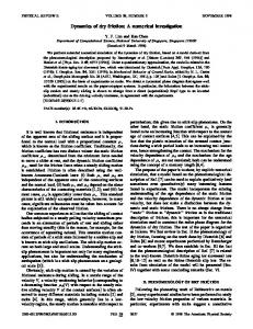
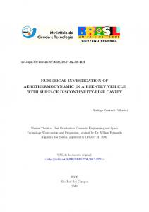
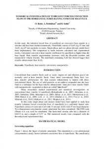
Fig. 1. Two dimensional schematic diagram The present study shows the same effects on a three dimensional cavity for very small Richardson numbers; and it includes a comparison for the same case with the one made by A.M. Al-Amiri et al. for the purpose of validation. The case of comparison is the numerical simulation of combined thermal and mass transport in a square lid-driven cavity at Ri = 0.0004 performed by A.M. Al-Amiri et al. After the validation is completed, three dimensional cases for Ri = 0.00005, 0.0001, 0.0002 and 0.0003 were studied to show the application of the very small Ri on the cavity. Isotherms and the velocity profiles as well as the Nusselt number for five sections inside the cavity were illustrated for each Ri: at X/L = 1/2, X/L = 1/4, X/L = 1/8, X/L = 1/16 and X/L = 1/32 as shown in fig.2a.The three dimensional case boundary conditions are shown in fig. 2b.
Fig. 2a. Three dimensional schematic diagram- Sections studied inside the cubic cavity
2
Copyright © 2015 by ASME
Downloaded From: http://proceedings.asmedigitalcollection.asme.org/ on 04/06/2016 Terms of Use: http://www.asme.org/about-asme/terms-of-use
U
∂V ∂V ∂V +V +W ∂X ∂Y ∂Z =−
U
∂W ∂W ∂W +V +W ∂X ∂Y ∂Z =−
U
∂P 1 ∂2 V ∂2 V ∂2 V Gr + ( + + ) + ( 2 θ) (3) ∂Y Re ∂X 2 ∂Y 2 ∂Z2 Re
∂P 1 ∂2 W ∂2 W ∂2 W + ( + + ) ∂Z Re ∂X 2 ∂Y 2 ∂Z2
∂θ ∂θ ∂θ 1 ∂2 θ ∂2 θ ∂2 θ +V +W = ( 2 + 2 + 2) ∂X ∂Y ∂Z Re. Pr ∂X ∂Y ∂Z
(4)
(5)
Where U, V and W are the dimensionless velocity components in the X-, Y-, and Z-directions, respectively, P is the dimensionless pressure, θ is the dimensionless temperature. Here, all distances are normalized by the cavity height L (X=x/L, Y=y/L, Z=z/L), all velocities are normalized by the lid velocity U0 (U=u/U0, V=v/U0, W=w/U0), and pressure is normalized by ρU02; ρ being the fluid density. The temperature is normalized as θ = (T-TC)/ (TH-TC). The dimensionless parameters appearing in Eqs. (2)–(5) are the Reynolds number Re = U0H/ν, the Prandtl number Pr = ν/α, the Grashof number Gr=gβ(TH-TC)H3/ν2, where ν is the kinematic viscosity and α is the thermal diffusivity of the fluid, β is the thermal expansion coefficient of the fluid, and g is the gravitational acceleration. The ratio Gr/Re2 is the mixed convection parameter and is called the Richardson number Ri and is a measure of the relative strength of the natural convection and forced convection for a particular problem. If Ri > 1 then natural convection is dominant. For problems with Ri ~ 1 then the natural convection effects are comparable to the forced convection effects. The boundary conditions for the present case of study are specified as follows: Top wall: U = 1, V = 0, W = 0, θ = 0 Bottom wall: U = V = W = 0, θ = 1 Right and left walls: U = V = W = 0, ∂θ/∂X = 0 Front and back walls: U = V = W = 0, ∂θ/∂Z = 0
Fig. 2b. Three dimensional schematic diagram- Operating conditions on the cavity. As shown in the fig. 2, the top wall is cold at uniform temperature and is moving in the positive x-direction while the bottom wall fixed with hot temperature. All the other walls are insulated and the gravity force is acting in the negative ydirection. MATHEMATICAL FORMULATION The physical model considered here is shown in Fig. 1; it is a square cavity with unity aspect ratio of dimension, L×H. The isothermal top and bottom walls are maintained at temperatures TC and TH, respectively, with TH> TC and the top wall is moving with a velocity of U0. The left and the right walls are adiabatic (insulated). The validation is made by the comparison of the present results with the previous results (obtained by A.M. AlAmiri et al.) in streamlines and isotherms for Ri = 0.0004 only. In the three dimensional case the same principles were applied; the physical model considered is a cubic cavity with unity aspect ratio of dimension, L x W x H. The isothermal top and bottom walls are maintained at temperatures TC and TH, respectively, with TH> TC and the top wall is moving to the right at velocity U0 (positive x-direction). The rest of the walls are adiabatic (insulated). The case was studied for Ri = 0.00005, 0.0001, 0.0002 and 0.0003 to show the effect of very small Ri on the flow inside the cavity. The dimensionless case was calculated in the same way as before.
The same governing equations of the three dimensional case (continuity, momentum and energy equations) were used for the two dimensional case for a steady, two-dimensional laminar flow (any property in the z-direction was eliminated).
The governing equations (continuity, momentum and NUMERICAL PROCEDURE
energy equations) for a steady, three-dimensional laminar flow are expressed as follows: ∂U ∂V ∂W + + =0 ∂X ∂Y ∂Z U
∂U ∂U ∂U ∂P 1 ∂2 U ∂2 U ∂2 U +V +W =− + ( + + ) ∂X ∂Y ∂Z ∂X Re ∂X 2 ∂Y 2 ∂Z2
The set of governing equations are integrated over the control volumes, which produces a set of algebraic equations. The SIMPLE algorithm is used to solve the coupled system of governing equations. The set of algebraic equations are solved sequentially. A second-order upwind differencing scheme is used for the formulation of the convection contribution to the coefficients in the finite volume equations. Central differencing
(1)
(2)
3
Copyright © 2015 by ASME
Downloaded From: http://proceedings.asmedigitalcollection.asme.org/ on 04/06/2016 Terms of Use: http://www.asme.org/about-asme/terms-of-use
is used to discretize the diffusion terms. The computation is terminated when the residuals for the continuity and momentum equations get below 10-3 and the residual for the energy equation gets below 10-6. The more stringent convergence criterion for the energy equation is used to ensure global heat balance. RESULTS AND DISCUSSIONS VALIDATION RESULTS The working fluid is chosen to be air with Prandtl number, Pr = 0.7 and Lewis number is assumed to be unity as there is no mass diffusion considered in the present study. The Grashof number, Gr, is fixed at 100 and the aspect ratio is taken to be 1. The Richardson number, Ri, is 0.0004 producing a corresponding Reynolds number, Re, of 500. From the previous study of A.M. Al-Amiri et al. [11] a grid of 91 × 91 was used. In the present study a grid dependency test was carried out and a structured grid of 151 × 151 with clustering towards the cavity walls was used to give more stable and accurate results. Fig.3 and Fig.4 show a comparison of streamlines and isotherms between the previous study of A.M. Al-Amiri et al. [11] and the present study.
Fig. (4.c) Temperature profile along the midsection of the cavity for Ri = 0.01. THREE DIMENSIONAL CASE RESULTS: The influence of varying the very small Richardson number Ri on the transport phenomena is shown in the following figures. Figs.5-8 show the velocity distribution for the five sections in the cavity for Ri = 0.00005, 0.0001, 0.0002 and 0.0003 respectively. In general, the highest effect of the velocity is shown at the midsection where the velocity reduces as the sections get near the insulated steady wall. This is due to the increase of friction effect which appears near the insulated walls hence reducing the fluid velocity. For Ri = 0.00005, the highest velocity distribution was observed at the midsection and it is more obvious at the right side of the cavity. Due to the moving top lid, there is a clockwise circulating vortex causing the center to have approximately constant velocity.
Fig. 3. Velocity Contours for Ri = 0.0004 (a) previous study (b) present study
(a)
(b)
(c)
Fig. 4. Isotherms for Ri = 0.0004 (a) previous study (b) present study (d) (e) Fig. 5. Velocity Contours for Ri = 0.00005 for the sections (a) 1/2 (b) 1/4 (c) 1/8 (d) 1/16 (e) 1/32
4
Copyright © 2015 by ASME
Downloaded From: http://proceedings.asmedigitalcollection.asme.org/ on 04/06/2016 Terms of Use: http://www.asme.org/about-asme/terms-of-use
(a)
(b)
circular vortex and as the section gets nearer to the steady wall and the effect of the friction is more visible. The velocity on the top wall is constant for all sections; but the difference in the velocity distribution between the top and the center of the cavity is affected dramatically between the sections. For lower Ri, it could be noticed that the effect of the friction gets more dominant on the flow near the steady wall. Comparing the cases of Ri=0.0002 and Ri=0.0001, at section 1/32, the velocity distribution is visible for Ri=0.0001 more than for Ri=0.0002. This leads to the point that, as the Ri decreases, the velocity decreases at the same section and that the friction affects the flow near walls. For Ri=0.0003, the results are nearly the same as for Ri = 0.0002 regarding the streamlines with minor differences noticed especially at section of 1/16. Regarding the temperature distributions in all cases, it is also noticed that temperature distributions was affected by the friction near the walls as the flow velocity decreases ,the heat transfer between the fluid layers decrease. As shown in the figures, the temperature distribution decreases for the same section as the Ri increases. For the same Ri as the section gets nearer to the steady wall, the friction increases causing decrease in the velocity which decreases the heat transfer. Fig.9, Fig.10, Fig.11, and Fig.12, show the temperature distributions for five sections in the cavity when Ri = 0.00005, 0.0001, 0.0002 and 0.0003 respectively.
(c)
(d)
(e)
Fig. 6. Velocity Contours for Ri = 0.0001 for the sections (a) 1/2 (b) 1/4 (c) 1/8 (d) 1/16 (e) 1/32
(a)
(b)
(d)
(c)
(e)
(a)
(b)
(c)
Fig. 7. Velocity Contours for Ri = 0.0002 for the sections (a) 1/2 (b) 1/4 (c) 1/8 (d) 1/16 (e) 1/32
(d) (e) Fig. 9. Isotherms for Ri = 0.00005 for the sections (a) 1/2 (b) 1/4 (c) 1/8 (d) 1/16 (e) 1/32 (a)
(b)
(c)
(a)
(d) (e) Fig. 8. Velocity Contours for Ri = 0.0003 for the sections (a) 1/2 (b) 1/4 (c) 1/8 (d) 1/16 (e) 1/32 For Ri=0.0001, the velocity in general is lower than for Ri=0.00005. This decreases the strength of the clockwise
5
(b)
(c)
Copyright © 2015 by ASME
Downloaded From: http://proceedings.asmedigitalcollection.asme.org/ on 04/06/2016 Terms of Use: http://www.asme.org/about-asme/terms-of-use
cavity. This means that the forced convection forms a vortex in the center of the cavity causing all particles move towards this vortex. Hence, this mechanism assures that the forced convection supported by the flow from the natural convection near the left wall, whereas it opposes the forced convection flow near the right wall. (d)
(e)
Fig. 10. Isotherms for Ri = 0.0001 for the sections (a) 1/2 (b) 1/4 (c) 1/8 (d) 1/16 (e) 1/32
Fig. 13. Particle Path-lines Colored by Velocity (a)
(b)
(d)
(c)
(e) Fig. 14. Particle Path-lines Colored by Temperature
Fig. 11. Isotherms for Ri = 0.0002 for the sections (a) 1/2 (b) 1/4 (c) 1/8 (d) 1/16 (e) 1/32
(a)
(b)
(d)
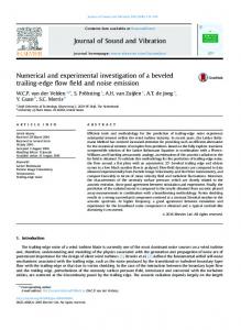
Fig.15, Fig.16, Fig. 17, and Fig. 18 show the distribution of Nusselt number along the different sections inside the cavity at Ri = 0.00005, 0.0001, 0.0002, and 0.0003 respectively. For Ri = 0.00005 at the bottom wall, the highest Nu is found at the section 1/8 whereas the sections 1/2 and 1/4 give nearly the same Nu distribution along the cavity. As the section gets nearer to the wall at sections 1/16 and 1/32 the Nu drops dramatically causing very low heat transfer. Nu changes slightly between the sections but not as much as for the bottom wall (the change in the bottom wall is more visible as Nu is relatively low). The maximum Nu is found at section 1/8 then decreases at section 1/16 which is very close section 1/4. The lowest Nu is found at section 1/32 and this is common for top and bottom walls. It was expected that the maximum Nu would be at the midsection but as investigated in this study the particles take a different path inside the cavity which increases heat transfer at section 1/8.
(c)
(e)
Fig. 12. Isotherms for Ri = 0.0003 for the sections (a) (a) 1/2 (b) 1/4 (c) 1/8 (d) 1/16 (e) 1/32 Fig.13 and Fig.14, show the path lines for the velocity magnitude and the temperature gradient respectively in three dimensional cavity for Ri = 0.00005, 0.0001, 0.0002, and 0.0003.The figures show the value of the property as the particle moves inside the cavity; it is clear that the particles move from the front and back walls into the center of the
6
Copyright © 2015 by ASME
Downloaded From: http://proceedings.asmedigitalcollection.asme.org/ on 04/06/2016 Terms of Use: http://www.asme.org/about-asme/terms-of-use
Fig. 15a. Local Nusselt numbers at different sections for Ri = 0.00005- bottom wall
Fig. 16a. Local Nusselt numbers at different sections for Ri = 0.0001- bottom wall
Fig. 15b. Local Nusselt numbers at different sections for Ri = 0.00005- top wall
Fig. 16b. Local Nusselt numbers at different sections for Ri = 0.0001- top wall
For Ri = 0.0001, the Nu for the sections 1/2, 1/4 and 1/8 at the bottom wall are very near to each other. The maximum values of Nu was achieved at section 1/4 then decreases at section 1/2 and 1/8 respectively. The minimum Nu was found at section 1/32 at the bottom wall. Regarding the top wall, the maximum Nu was found at sections 1/8 and 1/16. It was noticed that the maximum local Nu was not found at the midsections which proves that the flow in three dimensional cavities act differently than in two dimensional cases; top velocity at the midsection causing the flow to move in the y-direction giving a maximum Nu at other sections.
The discrepancy between the Nu along the different sections are more obvious for the bottom wall at Ri = 0.0002. Maximum Nu was found at section 1/4 due to the movement of flow in the y-direction from the top wall, then lower Nu was found at section 1/2 then subsequently sections 1/8, 1/16 and 1/32 respectively. For the top wall the Nu decreases at the midsection and section 1/32 but increases in the other sections.
7
Copyright © 2015 by ASME
Downloaded From: http://proceedings.asmedigitalcollection.asme.org/ on 04/06/2016 Terms of Use: http://www.asme.org/about-asme/terms-of-use
Fig. 17a. Local Nusselt numbers at different sections for Ri = 0.0002- bottom wall
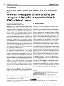
Fig. 18b. Local Nusselt numbers at different sections for Ri = 0.0003- top wall In general, it was found that, the lowest Nu is always at the section 1/32 for both top and bottom walls. It is also obvious for the top wall that the maximum Nu is found at section 1/8. For the bottom wall the cases are a bit different; the maximum Nu for all Ri is at section 1/4 except for Ri = 0.00005, the maximum Nu was found at section 1/8. This is due to the maximum velocity obtained in this case and hence the particles inside the cavity take a deeper path inside the sections (due to high velocity on the top wall giving an overall turbulent motion of the flow inside the three dimensional cavity). Fig.19 shows the average Nu against Ri for the different sections inside the cavity. For the bottom wall at Ri = 0.00005, the average Nu was highest at section 1/8, whereas for the other cases, the highest average Nu was found at section 1/4, then 1/2, 1/8, 1/16 and lastly 1/32. Regarding the top wall, the average Nu was highest at section 1/8, then 1/16, 1/4, 1/2, and lastly 1/32.
Fig. 17b. Local Nusselt numbers at different sections for Ri = 0.0002- top wall For the top and bottom walls of Ri = 0.0003 case, it is clear that the results are nearly the same as for Ri = 0.0002 with some differences in the values of Nu only, but the same trend was found for both Ri.
Fig. 19. Average Nu against Ri for all sections Fig. 18a. Local Nusselt numbers at different sections for Ri = 0.0003- bottom wall
8
Copyright © 2015 by ASME
Downloaded From: http://proceedings.asmedigitalcollection.asme.org/ on 04/06/2016 Terms of Use: http://www.asme.org/about-asme/terms-of-use
except at the Ri = 0.00005 where the highest Nu for the bottom wall was at the section 1/8. Average Nusselt Number was plotted against the Richardson Numbers for each section in the three dimensional cavity for the bottom wall and the top wall. A correlation was formulated for all sections on both walls for Average Nu as a function of Ri and section position (X/L). The maximum error for this correlation was 8%. This three dimensional case could be used for future studies for different Richardson numbers. The detailed study on the three dimensional case showed the streamlines, isotherms and the Nusselt number at different sections inside the three dimensional cavity for very small values of Richardson number.
Nu against Ri Fig. 20. Maximum Deviation for ̅̅̅̅
NOMENCLATURE
Form the results obtained in the present study; equation 6 represents an empirical correlation for the average Nu within the cavity as a function of (Ri) and section position (X/L). The curves of this correlation are also shown and compared with the numerical results in Fig. 19. The empirical correlation shows a maximum deviation of 8% which found to be in a good agreement with the numerical results as shown in Fig. 20.
A G Gr H K L Le N P Pr Re Ri TC TH u, v U, V U0 x, y X, Y W
−0.272
0.31 𝑅𝑖 ] (𝑋⁄𝐿)
̅̅̅̅ 𝑁𝑢 = [
5 ⨯ 10−5 ≤ Ri ≤ 3 ⨯ 10−4
(6)
CONCLUSIONS In the present study it was found that there is a good agreement between the present work and the previous studies. The validation is made for the cavity as a whole which ensures the correct use of the parameters and the model used for simulation process. From the present work, the Nusselt number is plotted against the top and bottom walls in a three dimensional cavity for different Richardson numbers. The heat transfer on the top wall is relatively high in comparison with the bottom wall. Highest Nu reached on the top wall was about 42 at Ri = 0.00005 at the 1/16 section while the highest on the bottom wall was about 38 at the same Ri but at the 1/8 section. The heated bottom wall increases the heat transfer on the top moving lid because both the natural convection (due to the buoyancy force) and the forced convection (due to the moving lid) were acting mainly on the top left part of the cavity. The three dimensional case proved that two dimensional cases are not accurate regarding other sections than the mid-section. The three dimensional case was compared with the present two dimensional case and the results have shown that the two dimensional case could only be used to show the profile of the curves; but to get the real accurate figures of the case a three dimensional case have to be applied. In general, the lowest Nu was always at the section 1/32 for both walls. The highest Nu was always at the section 1/8 for the top wall, while it was at the section 1/4 for the bottom wall
α β θ ρ ν
aspect ratio of the cavity, L/H gravitational acceleration Grashof number height of the cavity, m thermal conductivity of fluid, W m-1K-1 length of the cavity, m Lewis number buoyancy ratio parameter dimensionless local pressure Prandtl number Reynolds number Richardson number Gr/Re2 top wall temperature bottom wall temperature velocity components along x- and y-axes dimensionless velocity components top wall velocity Cartesian coordinates dimensionless coordinates Width of the cavity, m Greek Symbols thermal diffusivity, m2s-1 thermal expansion coefficient, K-1 dimensionless temperature density, kg m-3 kinematic viscosity, m2s-1
REFERENCES [1]
Torrance, K., Davis R., Eike K., Gill, P., Gutman, D., Hsui, A., Lyons, S., Zien , H., 1972 Cavity flows driven by buoyancy and shear, J. Fluid Mech. 51- 221–231.
[2]
Moallemi, M., Jang, K., 1992, Prandtl number effects on laminar mixed convection heat transfer in a lid-driven cavity, Int. J. Heat Mass Transfer 35-1881–1892.
9
Copyright © 2015 by ASME
Downloaded From: http://proceedings.asmedigitalcollection.asme.org/ on 04/06/2016 Terms of Use: http://www.asme.org/about-asme/terms-of-use
[3]
[4]
[5]
[6]
[7]
[8]
Mohammad, A., Viskanta, R., 1992, Laminar flow and
[10] Lee, S., Chen, C., 1996, Finite element solutions of
heat transfer in Rayleigh–Bernard convection with shear,
laminar and turbulent mixed convection in a driven
Phys. Fluids 4 -2131–2140.
cavity, Int. J. Numer. Methods Fluids 23- 47–64.
Mohammad, A., Viskanta, R.,1994, Flow structures and
[11] Al-Amiri, A., Khanafer, K., Pop, I., 2007, Numerical
heat transfer in a lid-driven cavity filled with liquid
simulation of combined thermal and mass transportin a
gallium and heated from below, Exp. Thermal Fluid Sci.
square lid-driven cavity, International Journal of Thermal
9- 309–319.
Sciences 46- 662–671.
Mansour, R., Viskanta, R., 1994, Shear-opposed mixed-
[12] Teamah,
El-Maghlany,
W.,2010,
Numerical
convection flow heat transfer in a narrow, vertical cavity,
simulation of double-diffusive mixed convective flow in
Int. J. Heat Fluid Flow 15- 462–469.
rectangular enclosure with insulated moving lid, Int. J.
Iwatsu, R., Hyun, J., Kuwahara, K., 1993, Mixed
Therm. Sci. 49-1625-1638.
convection in a driven cavity with a stable vertical
[13] Oztop, H., Dagtekin, I., 2004, Mixed convection in two-
temperature gradient, Int. J. Heat Mass Transfer 36-
sided lid-driven differentially heated square cavity, Int. J.
1601–1608.
Heat Mass Transfer 47- 1761–1769.
Iwatsu, R., Hyun, J., 1995, Three-dimensional driven
[14] Basak, T., Roy, S., Sharma, P., Pop, I., 2009, Analysis of
cavity flows with a vertical temperature gradient, Int. J.
mixed convection flows within a square cavity with
Heat Mass Transfer 38 - 3319–3328.
uniform and non-uniform heating of bottom wall, Int. J.
Mohammad, A., Viskanta, R., 1995, Flow and heat
Therm. Sci. 48- 891–912.
transfer in a lid-driven cavity filled with a stably stratified [9]
M.,
[15] Wright, J., Jim, H., Hollands, T., Naylor, D., 2006, Flow
fluid, Appl. Math. Model. 19 -465–472.
visualization of natural convection in a tall, air-filled
Prasad, A., Koseff, J., 1996, Combined forced and natural
vertical cavity, Int. J. Heat Mass Transfer 49- 889–904
convection heat transfer in a deep lid-driven cavity flow, Int. J. Heat Fluid Flow 17- 460–467.
10
Copyright © 2015 by ASME
Downloaded From: http://proceedings.asmedigitalcollection.asme.org/ on 04/06/2016 Terms of Use: http://www.asme.org/about-asme/terms-of-use