Latham damage criteria. ... Most frequently used models can be listed as Cockroft-Latham .... in the study of Zhang and Thomas [10], non-metallic oxide in-.
Author Dr. Cenk Kılıçaslan
Co- Author Umut İnce
Institution/ Company Norm Fasteners Co.
Numerical Investigation of Cold Forging and Failure Evolution of DIN 1.5535 Alloy M5x40 Bolts In this paper, cold forging and fracture of DIN 1.5535 M5x40 bolts were investigated experimentally and numerically. Thermo-mechanical simulations of forging operations were prepared in SIMUFACT FORMING finite element software. Failure evolution on simulated parts was predicted by using CockroftLatham damage criteria. Forging experiments showed that fracture propagated in straight or inclined directions though flange of the bolt. Numerical models and experiments revealed that punch deviation during forging was responsible of inclined cracks while straight cracks were related to raw material defect. It was also shown that damage model results should be also coupled with stress triaxiality to understand the mechanism of fracture evolution. Keywords: Cold forging, crack, fracture, simulation, numerical
1. Introduction Nowadays, almost all manufacturing processes are coupled with computer simulations to eliminate problems related to design of products, tools or dies without conducting any trial and error tests. Commercially developed simulation softwares having thermo-mechanical nonlinear finite element (FE) codes allow engineers to determine possible failures before manufacturing the product. Especially in forming operations of metals, high failure prediction capability of FE softwares has been utilized by many engineers and researchers. This capability greatly effects manufacturing costs by extinguishing improper design of tools or dies. Cold forging is a net-shape forming method which allows designers to create parts with high production rates and good mechanical properties. Due to severe plastic deformation, high strain rates and lower material temperature in contrast to warm or hot forging operations, forming limit of the material can be exceeded during cold forging. Therefore, damage and ductile fracture may occur on the product. Ductile fracture is associated with evolution of micro voids in the matrix of the material. Process begins with the creation of a free surface generated by a particle that may be an inclusion or a second phase. A micro void forms around that particle. Under tensile stress, the void
106
starts to extend and associate with neighboring micro voids. After a critical void volume, material loses its capability to carry load and intergranular fracture happens. Detailed literature survey on ductile fracture mechanisms can be found in the study of Cao [1]. In numerical simulations of metal forming operations, mathematical damage models are used to predict the failure. Most frequently used models can be listed as Cockroft-Latham [2], Lemaitre [3] and Johnson-Cook [4] failure models. CockroftLatham damage model is based on maximum principle stress and it is widely used to predict the evolution and the location of macro-fractures. Lemaitre model is a micro-mechanical model having ability to predict void formation and growth. JohnsonCook model considers the effects of strain, strain rate and temperature, however determination of model parameters are complex. More information about damage modeling in metal forming can be found in work of Saanouni et al. [5]. In the literature, there are many researches using these models in numerical simulations of metal forming. Samolyk et al. [6] investigated fracture generation on aluminum alloy work-piece during orbital forging using numerical simulations conducted on DEFORM finite element software. Cockroft-Latham model was used as a damage criteria. During forming, radially propagated cracks were seen on the surface of the parts. Maximum damage was seen to occur on the locations of cracks on the simulated parts. Bariani et al. [7] modified Xue and Wierzbicky damage model with a linear damage law and they compared the results to Oyane damage model results on cold forging of C35 Torx socket screw. In contrast to Oyane damage models, the modified damage model was seen to be able to predict the exact locations of fracture and the time in which material fails. Boyer et al. [8] modified Rice and Tracey damage model to include the effect of shear stress to predict void formation in the ductile metals. New damage model was seen to increase the accuracy of fracture evolution prediction. Despite there have been quite many studies about failure evolution in metal forming processes in the literature, researches on industrial applications of these models like multi-stage forging are quite rare. Motivated by this fact, cold forging and fracture evolution of DIN 1.5535 alloy M5x40 bolts were investigated experimentally and numerically. In the first part of the study,
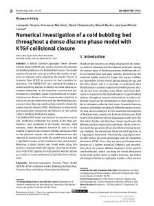
damaged bolts were examined and fracture locus on the bolts were determined. After that, simulations of the multi-forging operation of M5 bolts were prepared in commercial FE code SIMUFACT FORMING with Cockroft-Latham damage model. Lastly, numerical and experimental findings were compared. 2. Cold forging of M5x40 bolts M5x40 bolts were cold forged using DIN 1.5535 medium carbon steel billets in NORM Fasteners Co. on a machine having 40 tones maximum load capacity. Technical drawing and forming steps of the bolt are shown in Figure 1(a) and (b), respectively. Forming operation starts with heading and reduction of the cross-sectional area of the work-piece in the first station. Here, the initial diameter of the work-piece, 4.7 mm, was reduced to 4.33 mm in shaft section. In the following station, preforming of the head was conducted. The final shape of the head and socket are given in 3rd station. Fracture was generated on the bolt head during forming of the socket in this station.
ed that center point of the socket was deviated from the design geometry between 0.4 and 0.8 mm for bolts having inclined fracture as shown in Figure 3(a). On the other hand, no deviation was determined for bolts having perpendicularly propagated fracture (Figure 3(b)).
Fig. 3. Comparison of CAD models and damaged bolts with (a) inclined and (b) perpendicular fractures through flange. 3. Numerical models Numerical models of each forging station of M5 bolt were prepared in SIMUFACT FORMING commercial finite element software. Forging simulations were carried out using coupled thermo-mechanical analysis method. Figure 4 shows the models of the stations.
Fig.1. (a) Technical drawing and
Fig. 4. Numerical models of the forging stations of M5 bolts; (a) 1st, (b) 2nd and (c) 3rd stations.
(b) forging steps of M5x40 bolt. Macro-analysis were conducted on damaged bolts and they were categorized into two different groups according to fracture propagation paths. Fracture was initiated on the corner of T25 socket and propagated through the flange with an inclination angle changing between 52° and 57° or advanced perpendicularly as depicted in Figure 2(a) and (b), respectively.
Fig. 2. Fracture types on M5 bolts; (a) Inclined and (b) straight fractures. CAD model and pictures of damaged bolts were compared to determine any deviation from the designed geometry as shown in Figure 3 for both fracture types. Geometrical analysis show-
Numerical models consisted of moving and stationary dies and work-piece. Moving die was attached to the defined press and stationary die was constrained in all directions and rotations. Both dies were modeled as rigid. Work-piece was modeled as plastic material and elastic deformations were ignored due to prolonged CPU calculation times. Elastic deformations have negligible effects on the deformation of the material in a pure bulk forming operation like forging. Flow curves of DIN 1.5535 dependent on strain rates and temperatures chancing between 1-50 s-1 and 20-400 °C were defined to the software. CockroftLatham (CL) damage model was used in the numerical models. CL model formulation is given as; where, D, σmax, and are CL damage value, maximum principle stress, equivalent stress and equivalent plastic strain, respectively. In numerical models, it was assumed that fracture forms when CL damage value reaches unity. The first two stations were modeled as 2D due to axisymmetric condition while 3rd forging station was modeled as 3D. The FE mesh distributions of work-piece in 2D and 3D models are shown in Figure 5(a) and (b), respectively. In 2D simulations approximately 2600 numbers of quad-elements were used while 38000 numbers of hexahedral elements were defined for parts in 3D simulations. In 3rd station, socket and final head geometry of the bolt is formed and plastic deformation is localized on the head section of the bolt. To decrease CPU time, the head section of the bolt
107
was meshed with smaller elements while the rest of the bolt was meshed with coarser elements as shown in Figure 5(b).
Fig. 5. Finite element mesh distributions of work-piece at (a) 2D and (b) 3D simulations. A set of simulations were also conducted by deviating the punch as 0.4 and 0.8 mm to investigate effects of punch deviation on fracture evolution.
Here, σ*, σh and σ are stress triaxiality, hydrostatic and equivalent stress, respectively. Hydrostatic stress is known to improve ductility of the material and responsible of triggering fracture evolution due to its tensile nature. When stress triaxiality reaches to positive values, failure strain of the material starts to decrease. Because of that, fracture may happen at lower failure strains. Figure 7 shows stress triaxiality distribution in 3rd station at varying punch stroke. With increment of the punch into the part, stress triaxiality values reaches positive maximum values, ~0.7, on the corners of the socket which is shown with arrows at 1.8 mm punch stroke. When forming of socket was completed, stress triaxiality dropped negative values after 3 mm punch stroke. This result showed that maximum tensile stresses were generated on the head near socket corners and any raw material defect or deviation from proper forming conditions may lead failures on these areas.
4. Results and discussions 4.1. Numerical modeling under perfect forging conditions On this section, numerical results of forging operation under perfect forming conditions (punch was not deviated) were presented. Effective plastic strain distribution on the parts at different forging stations are shown in Figure 6(a). In all stations, effective plastic strain was seen to be localized on the head section and maximum plastic strain was determined to be approximately 3.4 on the socket section of the bolt in 3rd station. There is no severe and localized plastic strain that may cause failure was detected on the fracture locus. CAD and simulation model of the part in 3rd station were compared in Figure 6(b). As shown in the figure, both geometry were seen to match with each other in all directions.
Fig. 7. Distribution of stress triaxiality on the part in 3rd station at varying punch strokes. Cockroft-Latham damage value distribution in 3rd station is given in Figure 8. As seen from the figure, maximum damage value was seen to be 0.56 which indicates that no failure is present on this station. Same as the stress triaxiality, maximum damage value first appeared on the corners of socket, then distributed outer part of the head and flange.
Fig. 6. (a) Effective plastic strain distribution and Fig. 8. Distribution of Cockroft-Latham damage value on the part in 3rd station at varying punch strokes.
(b) comparison of CAD model to simulation result. Following numerical studies were focused on the forming of the part in 3rd station to investigate the reasons of the fracture. In addition to plastic strain distribution, determining stress triaxiality distribution is also necessary to predict the damage evolution in metals [9]. Stress triaxiality is defined as following;
108
According to above mentioned results, no fracture was expected on the bolts under perfect forging conditions. As depicted in the study of Zhang and Thomas [10], non-metallic oxide inclusions or sliver defects (defects on the material surface which are parallel to rolling direction) are responsible of fractures on the parts manufactured by metal forming operations. Motivated by this, damaged bolts which have perpendicularly propagated fracture were etched and examined by using stereo zoom microscope. As shown in Figure 9, longitudinal surface defects were determined on the parts. During heading and socket forming, this defect triggered fracture initiation and caused to form an opening crack on the head.
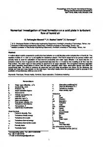
Fig. 9. Sliver defect on etched bolts having straight fracture. 4.2. Numerical modeling considering punch deviation Figure 10(a) and (b) shows CL damage value distribution on the bolts in 3rd station for punch deviations of 0.4 and 0.8 mm. By increasing punch deviation, damage value was seen to increase on both socket corners and flange. This may be attributed to decrease in the volume of the material in the direction of punch deviation which leads to increase in stress in a narrow area. High tensile stress on this area triggered the evolution and coalescence of voids leading a macro shear fracture. CL damage values were also gathered on these areas that experienced maximum damage and presented in Figure 10(c) for both punch deviations. As seen from the figure, maximum damage value was determined as 0.81 and 0.98 for 0.4 and 0.8 mm punch deviation, respectively. These results proved that deviation of the punch has a great influence on fracture initiation.
Fig. 10. Distribution of Cockroft-Latham damage value at punch deviation of (a) 0.4 and (b) 0.8 mm, and
5. Conclusions In this paper, cold forging and fracture of DIN 1.5535 M5x40 bolts were investigated experimentally and numerically. Thermo-mechanical simulations of forging operations were prepared in SIMUFACT FORMING finite element software, and reasons of fracture initiation in forging operation were revealed by examining mechanical variables like stress triaxiality and distribution of Cockroft-Latham damage values. According to numerical and experimental findings, following conclusions were drawn; • Numerical models of forging operation showed that fracture evolution was related to raw material defect or improper forging operation. • Analysis of bolts having straight fracture showed that bolts have sliver defect on their surface. Sliver defect was seen to lead crack opening and straight propagation of the fracture. • Numerical analysis proved that punch deviation during forging in 3rd station caused inclined fracture evolution on the bolt. • For better prediction of fracture in metal forging and better understanding of failure mechanism, damage model results should be coupled with stress triaxiality. References 1. Cao, T.S., Models for ductile damage and fracture prediction in cold bulk metal forming processes: a review. International Journal of Material Forming, 2015. 2. Cockroft, M.G. and D.J. Latham, Ductile and workability of metals. Journal of the Institute of Metals, 1968. 96: p. 33-39. 3. Lemaitre, J., A continuous damage mechanics model for ductile fracture. Journal of Engineering Materials and Technology, Transactions of American Society of Mechanical Engineers, 1985. 107: p. 9-83. 4. GR, J. and C. WH, Fracture chracteristics of 3 metals subjected to various strains, strain rates, temperatures and pressures. Engineering Fracture Mechanics, 1985. 21(1): p. 31-48. 5. Saanouni, K., K. Nesnas, and Y. Hammi, Damage Modeling in Metal Forming Processes International Journal of Damage Mechanics, 2000. 9: p. 196-240. 6. Samołyk, G., J. Tomczak, and J. Bartnicki, Cold Forming of AlCu4MgSi Alloy by Orbital Forging. Archives of Metallurgy and Materials, 2012. 57(1). 7. Bariani, P.F., et al., Ductile fracture prediction in cold forging process chains. CIRP Annals - Manufacturing Technology, 2011. 60(1): p. 287-290. 8. Boyer, J.-C., E. Vidal-Sallé, and C. Staub, A shear stress dependent ductile damage model. Journal of Materials Processing Technology, 2002. 121(1): p. 87-93. 9. Mirone, G. and D. Corallo, A local viewpoint for evaluating the influence of stress triaxiality and Lode angle on ductile failure and hardening. International Journal of Plasticity, 2010. 26(3): p. 348-371. 10. Zhang, L. and B.G. Thomas, Evaluation and control of steel cleanliness—review, in Proceedings of the 85th Steelmaking Conference. 2002: Warrendale, PA. p. 431-452.
(c) variation of damage value on fracture locus.
109