Dynamic free-fall penetrometers offer a potential for such rapid strength assessment, but have typically been employed in conjunction with mostly empirical.
abstract # 090612-058
NUMERICAL INVESTIGATION OF DYNAMIC FREEFALL PENETROMETERS IN SOFT COHESIVE MARINE SEDIMENTS USING A FINITE DIFFERENCE APPROACH Andrei Abelev, Kevin Tubbs, and Philip Valent Naval Research Laboratory, Stennis Space Center, MS 39529, USA Abstract: Rapid assessments of undrained shear strength of marine sediments are often of great interest in various branches of offshore civil and petroleum engineering, as well as the Navy. Dynamic free-fall penetrometers offer a potential for such rapid strength assessment, but have typically been employed in conjunction with mostly empirical relationships to investigate the undrained shear strengths of sediments. In this work, we analyze the behavior of STING (Sea Terminal Impact Naval Gauge) using the deceleration record of sediment impact. We modify an existing numerical technique for extraction of the undrained shear strength from the deceleration history of the probe. We utilize a finitedifference code for the analysis of continua (FLAC3D [1]) for solution of the penetrometer impact and penetration into the heterogeneous marine sediments. The numerical solutions are described in detail and address many aspects of modeling penetration resistance in cohesive materials. Analysis was performed into a number of numerical aspects of attaining the solution in FLAC3D, including the indeterminate contact geometry after discretization, and incompressibility of the deforming material and the influence of the Poisson’s ratio on the solution. Undrained deformation of the water saturated cohesive sediments is characterized by nearly incompressible response, leading to some difficulties in achieving accurate solutions. These effects were investigated and stable solutions were attained. Numerical predictions thus accomplished were compared with the values of the undrained shear strength, as determined in standard laboratory tests on specimens recovered from several locations in the Gulf of Mexico and showed good accuracy and large improvement over the original STING processing algorithm.
I.
EXPERIMENTAL EVIDENCE, EXISTING STING ALGORITHM, AND BEARING STRENGTH
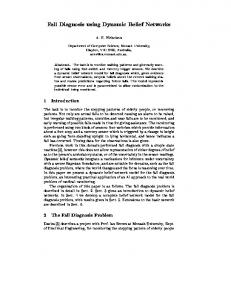
The STING is one of several probes that are designed to penetrate soft bottom marine sediments on impact after free-fall through the water column. Key measurements include deceleration and water pressure records, allowing for correlations yielding a description of the shear strength of the sediment and depth penetrated. A general view of the STING penetrometers is shown in Fig. 1. The body of the penetrometer contains all the sensor and data storage electronics and the probe is tethered via the end-cap for retrieval. The steel rods are 19 mm in diameter and can extend 1, 2, or 3 m, depending on expected penetration burial in sediments. The end-shapes include discs of four different diameters: 25, 35, 50, and 70 mm (Fig. 1). The probe is described in detail in [2]. Further details of the STING operating principles and processing software, as well as the general considerations on the applicability of the “bearing strength” parameters to evaluations of the undrained shear strength of cohesive water saturated sediments are given in the companion paper [3]. In general, Fig. 2 exemplifies a rather common experience with employing the original STING processing algorithm for derivation of the “bearing strength” with subsequent application of the undrained bearing capacity factor, N c , (purely cohesive materials) of 10 to reduce the bearing strength parameter to the undrained shear strength, SU :
SU = BS / N c .
1 0-933957-38-1 ©2009 MTS
(1)
Form Approved OMB No. 0704-0188
Report Documentation Page
Public reporting burden for the collection of information is estimated to average 1 hour per response, including the time for reviewing instructions, searching existing data sources, gathering and maintaining the data needed, and completing and reviewing the collection of information. Send comments regarding this burden estimate or any other aspect of this collection of information, including suggestions for reducing this burden, to Washington Headquarters Services, Directorate for Information Operations and Reports, 1215 Jefferson Davis Highway, Suite 1204, Arlington VA 22202-4302. Respondents should be aware that notwithstanding any other provision of law, no person shall be subject to a penalty for failing to comply with a collection of information if it does not display a currently valid OMB control number.
1. REPORT DATE
2. REPORT TYPE
JUN 2010
N/A
3. DATES COVERED
-
4. TITLE AND SUBTITLE
5a. CONTRACT NUMBER
Numerical Investigation Of Dynamic Freefall Penetrometers In Soft Cohesive Marine Sediments Using A Finite Difference Approach
5b. GRANT NUMBER 5c. PROGRAM ELEMENT NUMBER
6. AUTHOR(S)
5d. PROJECT NUMBER 5e. TASK NUMBER 5f. WORK UNIT NUMBER
7. PERFORMING ORGANIZATION NAME(S) AND ADDRESS(ES)
Naval Research Laboratory, Stennis Space Center, MS 39529, USA 9. SPONSORING/MONITORING AGENCY NAME(S) AND ADDRESS(ES)
8. PERFORMING ORGANIZATION REPORT NUMBER 10. SPONSOR/MONITOR’S ACRONYM(S) 11. SPONSOR/MONITOR’S REPORT NUMBER(S)
12. DISTRIBUTION/AVAILABILITY STATEMENT
Approved for public release, distribution unlimited 13. SUPPLEMENTARY NOTES
See also ADM202806. Proceedings of the Oceans 2009 MTS/IEEE Conference held in Biloxi, Mississippi on 26-29 October 2009. U.S. Government or Federal Purpose Rights License, The original document contains color images. 14. ABSTRACT
Rapid assessments of undrained shear strength of marine sediments are often of great interest in various branches of offshore civil and petroleum engineering, as well as the Navy. Dynamic free-fall penetrometers offer a potential for such rapid strength assessment, but have typically been employed in conjunction with mostly empirical relationships to investigate the undrained shear strengths of sediments. In this work, we analyze the behavior of STING (Sea Terminal Impact Naval Gauge) using the deceleration record of sediment impact. We modify an existing numerical technique for extraction of the undrained shear strength from the deceleration history of the probe. We utilize a finitedifference code for the analysis of continua (FLAC3D [1]) for solution of the penetrometer impact and penetration into the heterogeneous marine sediments. The numerical solutions are described in detail and address many aspects of modeling penetration resistance in cohesive materials. Analysis was performed into a number of numerical aspects of attaining the solution in FLAC3D, including the indeterminate contact geometry after discretization, and incompressibility of the deforming material and the influence of the Poissons ratio on the solution. Undrained deformation of the water saturated cohesive sediments is characterized by nearly incompressible response, leading to some difficulties in achieving accurate solutions. These effects were investigated and stable solutions were attained. Numerical predictions thus accomplished were compared with the values of the undrained shear strength, as determined in standard laboratory tests on specimens recovered from several locations in the Gulf of Mexico and showed good accuracy and large improvement over the original STING processing algorithm. 15. SUBJECT TERMS
16. SECURITY CLASSIFICATION OF: a. REPORT
b. ABSTRACT
c. THIS PAGE
unclassified
unclassified
unclassified
17. LIMITATION OF ABSTRACT
18. NUMBER OF PAGES
SAR
10
19a. NAME OF RESPONSIBLE PERSON
Standard Form 298 (Rev. 8-98) Prescribed by ANSI Std Z39-18
abstract # 090612-058
Fig. 1. STING penetrometers after deployment. Visible: 25, 35, 70mm “foot” plates
Fig. 2. Example of STING-calculated undrained shear strength, compared with that determined from lab vane tests (black curve with error-bars)
2
abstract # 090612-058
In this study, we focus on STING drops at three locations (stations) in the Gulf of Mexico. One example of shear strength at Station 3 is given in Fig. 2. A good agreement between the STING-derived SU based on the 70 mm foot and one acquired through standard lab vane test on undisturbed specimens (from gravity corer) is apparent. As the size of the STING foot is reduced, the deviations with the vane-measured SU become progressively more severe, with the results provided by the 25mm foot deployment being least accurate. Further discussion of these discrepancies is given in [3]. In this work, we develop a set of numerical techniques for extraction of the undrained shear strength from the deceleration history of the probe to improve the estimation. The algorithm adopted herein is generally similar to the one used in predicting the undrained shear strength from the XBP (eXpendable Bottom Profiler) probe, given in [4]. II.
NUMERICAL FORMULATION
Analysis of Bearing Resistance Analysis of probe impact and burial can be conducted using various approaches. One may attempt to produce full dynamic solutions, including large sediment deformation and flow around the penetrating STING, full elasto-plastic constitutive formulations and rate effects. One such analysis is presented in [3], using a finite element approach and including ALE (Arbitrary Lagrangian-Eulerian) remeshing scheme. Alternatively, one could utilize a pseudo-static approach (e.g. [4]) that computes a static collapse load for a pre embedded STING penetrometer at a series of depths, ranging from the sediment-water interface and down to a depth of about 3 meters (maximum STING embedment data available). The analysis neglects the effects of prior strains and deformations occurring during the penetration process and assumes the sediment to be at the in situ stress state. Although this approach clearly involves a major simplification, it has proven to be useful in a variety of applications such as: interpretations of in situ penetration tests such as the XBP probe [4], the ball penetrometer [5], and the T-bar penetrometer [6]; pipe penetration into the seafloor [7], cylinder embedment in cohesive soil [8] and capacity of plate anchors installed by drag embedment [9]. Equations of motion If the penetrometer is modeled as a single particle, the force balance acting on the penetrometer during penetration into the seafloor may be expressed as following:
(
)
Fs = Wb 1 - a g - Fb ,
(2)
where a – is acceleration, g – is the gravitational acceleration, Fs - is the sediment resistance force, Fb - is the buoyancy force, and Wb - is the water buoyant weight of the penetrometer. All motions of the penetrometer are assumed to be vertical, as no accelerometer readings occur in any direction normal to the long-axis of the probe and are thus unknown (unmeasured). Fin and trailing tether water drag stabilization during the fall through the water, as well as the relatively large mass of the penetrometer, are commonly considered sufficient to ensure vertical entry into the sediment. Common marine sediments can be highly variable and heterogeneous, but can generally be described as transversely-anisotropic, with properties in the horizontal plane all being equal and different to those along the vertical (depositional) direction. This leads to an assumption that the penetrometer remains vertical throughout the embedment process. The penetration of the STING probe occurs under the conditions of variable embedment and variable velocity, as the probe decelerates from its terminal velocity attained during the fall through the water column, and until it comes to a complete stop at full embedment in the sediment. Hence, the interpretive framework relating penetration resistance force to sediment strength must account for both the effects of the different burial depth, as well as dependency on the strain rate qualities characteristic of soft cohesive marine sediments [10-13]. Static bearing capacity factor Quasi-static loading conditions imply that the sediment penetration resistance force FS 0 is related to static undrained shear strength SU 0 by a dimensionless bearing capacity factor:
N c 0 = FS 0 SU 0A ,
3
(3)
abstract # 090612-058
where A is the contact area between the foot of the penetrometer and the sediment (foot diameter). For shallower embedment depths (up to five times the foot diameter [14]), the bearing capacity factor N c 0 varies as a function of embedment depth. For simplicity, the embedment depth may be converted to a dimensionless variable h d , where h is penetration depth and d is the diameter of foot of the penetrometer. Estimation of N c 0 as a function of h d is
one of the main goals of this work and has been accomplished, similarly to Reference [4], through a series of numerical computations. In this case, we use a commercial finite-difference software for the analysis of continua (FLAC3DTM – Fast Lagrangian Analysis of Continua). Material model The constitutive model used in this analysis assumes that the sediment is elasto-plastic and follows a MohrCoulomb yield criterion, and an associated flow law. Since a quasi-static analysis is conducted, the ultimate bearing load estimation should not, theoretically, be influenced by the choice of the elastic parameters, which are, however, necessary for completion of the numerical formulation. In practice, elastic parameters need to be chosen carefully, as FLAC3D did display some sensitivity to the elastic constants, primarily the Poisson’s ratio (see further discussion below). FLAC3D allows fully non-linear displacement analysis, and quadrilateral elements were selected for the problem. The algorithm adopted herein (as in [4]) assumes that a cylindrical void forms in the wake of the advancing penetrometer. This assumption may lead to some overestimation of the undrained shear strength, as it will not include the shearing resistance along the parts of the penetrometer shaft in the momentum balance calculations, and therefore will not account for the energy dissipated in that region. It is possible that this contribution, however, is relatively small, considering that the sediment in contact with the shaft will be severely remolded and likely to have a much degraded value of the undrained shear strength. Discretization Numerical analysis was performed using a fully three dimensional model, using only a quarter of the geometry due to symmetry considerations. Fig. 3 shows the FLAC3D grid used for the case of a STING embedded at a depth B . A finer mesh at the edges of the STING foot area was needed primarily to minimize errors in the numerical ambiguity of the actual size of the loaded area. These ambiguities have been discussed in detail in [1,15]. Along the STING-sediment interface, a rough sediment-probe boundary is assumed; i.e., no relative movement occurs between sediment and probe. The top surface of the domain represents the sediment surface and is set as traction-free. The far-field boundaries for the Z = 0 plane and r = (x 2 + y 2 )2 = A + C and the planes of symmetry, Y - Z and X - Z are fixed.
Fig. 3. FLAC3D discretization mesh for an embedment depth B
4
abstract # 090612-058
The analysis is conducted where the limiting load on the STING foot, leading to the collapse conditions (failure), is maximized. An example of the calculation results is presented in Fig. 4, showing the velocity contours at failure and velocity vectors, and demonstrating the extent and the pattern of the developed plastic flow zone.
Fig. 4. Example of the velocity magnitude contours and velocity vectors (close-up) showing the confined area of plastic flow
A comprehensive analysis was performed into a number of numerical aspects of attaining the stable solution in FLAC3D, including the indeterminate contact geometry after discretization, as noted before, as well as the effects of the incompressibility of the deforming material. Undrained deformation of the water saturated cohesive sediments is characterized by nearly incompressible response, leading to difficulties in achieving accurate solutions while minimizing the overall code runtime. Increasingly incompressible media require progressively smaller time steps to be undertaken to ensure numerical stability. Sensitivity analysis To investigate the effects of the Poisson’s ratio (or incompressibility) on the solution accuracy and runtime, the bearing capacity factor, N c was calculated for a surface load so that results could be compared with the established solutions. For this purpose, the bulk modulus was fixed and the shear modulus was varied, exploring a range of the Poisson’s ratios. Fig. 5 shows the convergence of the bearing capacity factor and the changes in the number of cycles needed to reach a stable solution in relation to the selected Poisson’s ratio. It is also possible that the values of the Poisson’s ratio very close to 0.5 maybe somewhat unrealistic, similar to the infinite ratio of the bulk to shear modulus that this would imply [16]. Based on these investigations, a Poisson ratio of 0.49 was chosen and used for all other simulations in this work, representing a rather typical selection for these types of problems. Validation of the numerical calculations was conducted for a loading on the sediment surface (zero penetration depth) to a normalized depth of five diameters, and compared with the accepted solutions [14]. Fig. 6 shows the results and the good agreement that was attained.
5
abstract # 090612-058
Fig. 5. Poisson’s ratio influence on the bearing capacity factor,
Nc
and the number of cycles necessary to reach the solution
Fig. 6. Comparison of the FLAC3D simulations with Skempton, 1951 results [14] for the surface loading of a circular footing (STING)
Strain-rate dependence Dependence of the soil resistance on the rate of loading is discussed in further details in [13]. In this work, a simplified expression developed by [4] is adopted: é æ v ö÷ù ÷÷ú , (4) N c = N c 0 êê1 + l log10 ççç ú ç d e è 0 ø÷÷úû êë
6
abstract # 090612-058
where v – is the velocity of the probe, d – foot diameter, e0 is the reference strain rate, and l - is the material parameter. The parameters were selected as follows: e0 = 0.05%/hr and l = 0.15, as in [4], as appropriate to modeling the response of the sediments considered, i.e. soft sediments from the North coastal regions of the Gulf of Mexico. Simulations Figure 7 shows the prediction results for the bearing capacity factor, corresponding to the conditions ranging from zero velocity and up to the maximum initial velocity of 5.3 m/s (experimentally encountered in STING deployments) and variable embedment depths. Solid symbols represent individual FLAC3D predictions and the dashed lines represent the polynomial fits, computed from the simulation results for ease of application in the STING processing algorithm. The following polynomial equations were found:
( )
Nc 0 = a4 h d
4
( )
+ a3 h d
3
( )
+ a2 h d
2
( )
+ a1 h d + a 0 ,
(5)
where a 4 = - 0.0058, a 3 = 0.1099, a2 = - 0.7505, a1 = 2.2623, a 0 = 6.2923 . The fitted equations provide good representations of the numerical results, as shown in Fig. 7.
20
v=5.3 m/s
18 v=0.1 m/s 16
v=0.01 m/s
Bearing Factor, Nc
14 v=0.0001 m/s 12 10
v=0 m/s
8 6 4 2 0
0
1
2
3
4 5 6 Penetration Depth, (h/d)
Fig. 7. FLAC3D computed bearing capacity factor,
7
8
9
10
N c , as a function of the burial depth and loading velocity
Algorithm for STING Data Interpretation Estimation of the sediment undrained shear strength profile from STING data is calculated through the following steps, similarly to the algorithm given in [4]: 1. Deceleration record is obtained from STING deployment, a(t ) ; 2.
Soil resistance force, Fs , is determined from Eq. 2 at each time step in the STING deceleration time series;
3.
Acceleration a(t ) is integrated to obtain a history of velocity v(t ) and embedment depth h throughout penetration;
7
abstract # 090612-058
4.
æh ö The bearing factor N c ççç , v ÷÷÷ is calculated using Eqs. 4 and 5; çèd ø÷
5.
Undrained shear strength, SU 0 , is then determined from Eq. 3. III.
DETERMINATION OF UNDRAINED SHEAR STRENGTH FROM STING DATA
The results and algorithm presented above are applied to STING data collected in the Gulf of Mexico at three different locations. All three of these locations (stations) are characterized by soft cohesive sediments (> 3 m deposits). All three cases involve a STING configuration with 2 m long shaft and a 25 mm foot diameter, chosen because it produces the worst prediction of the undrained shear strength of all foot sizes tested when utilizing the native processing algorithm. The buoyant weight of the STING is 9.58 kgf and buoyant unit weight of the sediment is taken to be 650 kg/m3. Figure 8 shows the much improved estimations of sediment shear strength as the penetration depth increases, matching well the results of the undrained shear strength determined in the lab using vane tests (black solid lines with error-bars, representing the standard deviation in measurements). The sediment strength is somewhat overestimated for the small penetration depths. We believe that this may due to inertial effects of the sediment, which were not incorporated into this analysis. These effects were not included when computations were done on STING being “pre-placed” to a certain depth of interest. Sediment disturbance history is another effect ignored in our pseudo-static analysis. The presence of several sharper “spikes” in the STING-processed data, present to a smaller degree in our simulations, represent a phenomenon not addressed here. These spikes, or added resistance to penetration of the probes, are thought to be due to thin lenses of silty or sandy materials. These effects have been noted before [17-19] but are not addressed in this study.
8
abstract # 090612-058
this work this work STING STING
P03, ST#: 3 0 20
this work
40
Depth (cm)
60 80
STING
100 120 140 160 180 200
0
5
10
15
20
25
30
Soil Strength (kPa)
Fig. 8. STING-processed (magenta) and FLAC3D-computed (red) undrained shear strength computation from three locations in the Gulf of Mexico, compared with the lab-measured vane test results (black solid lines with error-bars representing the standard deviation in strength measurements)
IV.
CONCLUSIONS
An algorithm developed earlier [4] was modified and applied for calculating sediment undrained shear strength from STING penetrometer deceleration data. The calculations included buoyancy and strain rate dependent effects, but disregarded the sediment disturbance and deformation history by utilizing the pseudo-static approach. For small penetrometer footings, i.e. (< 70 mm), the native STING data processing algorithm may severely overpredict the undrained shear strength, SU , especially at smaller foot sizes and greater penetration depths. Numerical simulations using FLAC3D were performed to improve this processing algorithm. The solutions generated here showed significant improvement of the estimations of SU with increasing depth while somewhat over-estimating
SU for shallow probe embedment. The case of the STING 25 mm foot was chosen as one providing the poorest estimation of the undrained shear strength using native processing software, as compared with the standard labproduced vane shear results. The results obtained in our simulations prove the utility of the algorithm chosen and will be extended to other STING foot sizes in the future. V.
ACKNOWLEDGMENTS
This research is supported by Program Element No. 61153N of the Naval Research Laboratory and the Office of Naval Research. The help of the crews and research teams, much too numerous to list here but instrumental in obtaining the field data including penetrometer records is greatly appreciated.
9
abstract # 090612-058
VI.
REFERENCES
[1] Itasca Ltd., FLAC3D - Fast Lagrangian Analysis of Continua in 3 Dimensions - User’s Guide, Minneapolis, Minnesota: 2006. [2] R. Poeckert, J. Preston, T. Miller, R. Religa, and A. Eastgaard, A seabed penetrometer. DREATechnical Memorandum, Dartmouth, Nova Scotia: 1997. [3] A. Abelev, J. Simeonov, and P.J. Valent, “Numerical investigation of dynamic free-fall penetrometers in soft cohesive marine sediments using a finite element approach,” Oceans 2009, IEEE/MTS conference, Biloxi, MS: 2009. [4] C.P. Aubeny and H. Shi, “Interpretation of Impact Penetration Measurements in Soft Clays,” Journal of Geotechnical and Geoenvironmental Engineering, vol. 132, 2006, p. 770. [5] M.F. Randolph, C.M. Martin, and Y. Hu, “Limiting resistance of a spherical penetrometer in cohesive material,” Geotechnique, vol. 50, 2000, pp. 573–582. [6] D. Stewart and M. Randolph, “T-bar penetration in soft clay,” Journal of Geotechnical Engineering, ASCE, vol. 118, 1994, pp. 2230–2235. [7] J.D. Murff and D. Wagner, “Pipe penetration in cohesive soil,” Géotechnique, vol. 39, 1989, pp. 213–29. [8] C.P. Aubeny, H. Shi, J.D. Murff, and others, “Collapse loads for a cylinder embedded in trench in cohesive soil,” International Journal of Geomechanics, vol. 5, 2005, p. 320. [9] J.D. Murff, M.F. Randolph, S. Elkhatib, H.J. Kolk, R. Ruinen, P.J. Strom, and C. Thorne, “Vertically loaded plate anchors for deepwater applications,” Proc Int Symp on Frontiers in Offshore Geotechnics, London: Taylor & Francis, 2005, pp. 31–48. [10] G. Biscontin and J.M. Pestana, “Influence of Peripheral Velocity on Vane Shear Strength of an Artificial Clay,” GEOTECHNICAL TESTING JOURNAL, vol. 24, 2001, pp. 423-429. [11] K. Kim, M. Prezzi, R. Salgado, and W. Lee, “Effect of Penetration Rate on Cone Penetration Resistance in Saturated Clayey Soils.,” Journal of Geotechnical & Geoenvironmental Engineering, vol. 134, 2008, pp. 1142-1153. [12] J. Locat and D. Demers, “Viscosity, yield stress, remolded strength, and liquidity index relationships for sensitive clays,” Canadian Geotechnical Journal, vol. 25, 1988, pp. 799-806. [13] A. Abelev and P.J. Valent, “Strain-rate dependency of strength and viscosity of soft marine deposits of the Gulf of Mexico,” Biloxi, MS: 2009. [14] A. Skempton, “The bearing capacity of clays,” Proc. Bldg. Research Congress, 1951. [15] S.W. Sloan and M.F. Randolph, “Numerical prediction of collapse loads using finite element methods,” International Journal for Numerical and Analytical Methods in Geomechanics, vol. 6, 1982, pp. 47-76. [16] P. Mott, J. Dorgan, and C. Roland, “The bulk modulus and Poisson's ratio of "incompressible" materials,” Journal of Sound and Vibration, vol. 312, May. 2008, pp. 572-575. [17] R.D. Stoll, Y.F. Sun, and I. Bitte, “Measuring sea bed properties using static and dynamic penetrometers,” Civil engineering in the Oceans VI, 2004, pp. 386–395. [18] D. Stoll, Y.F. Sun, and I. Bitte, “Seafloor properties from penetrometer tests,” IEEE Journal of Oceanic Engineering, vol. 32, 2007, pp. 57–63. [19] R. Stoll and Y. Sun, Using Penetrometers to Measure Sea Bed Properties, 2005.
10