Progress In Electromagnetics Research B, Vol. 51, 135–156, 2013
NUMERICAL METHOD OF COMPUTING IMPEDANCES IN SHIELDED AND UNSHIELDED THREE-PHASE RECTANGULAR BUSBAR SYSTEMS Zygmunt Piatek1, * , Bernard Baron2 , Pawel Jablonski3 , Dariusz Kusiak3 , and Tomasz Szczegielniak1 1 Faculty
of Environmental Engineering and Biotechnology, Czestochowa University of Technology, 60A, Brzeznicka St., Czestochowa 42200, Poland 2 Faculty
of Electrical Engineering, The Silesian University of Technology, 10, Akademicka St., Gliwice 44-100, Poland 3 Faculty
of Electrical Engineering, Czestochowa University of Technology, 17, Armii Krajowej Av., Czestochowa 42-200, Poland Abstract—In this paper, a new numerical method of calculating rectangular busbar impedance is proposed. This method is based on integral equation method and partial inductance theory. In particular, impedances of shielded and unshielded three-phase systems with rectangular phase and neutral busbars, conductive enclosure, and use of the method are described. Results for resistances and reactances for these systems of multiple rectangular conductors have been obtained, and skin and proximity effects have also been taken into consideration. The impact of the enclosure on impedances is also presented. Finally, two applications to three-phase shielded and unshielded systems busbars are described. The validation of the proposed method is carried out through FEM and laboratory measurements, and a reasonable level of accuracy is demonstrated. 1. INTRODUCTION The high-current air-insulated bus duct systems with rectangular busbars are often used in power generation and substation, due to their easy installation and utilization. The increasing power level of these plants requires an increase in the current-carrying capacity of the Received 2 March 2013, Accepted 22 April 2013, Scheduled 26 April 2013 * Corresponding author: Zygmunt Piatek (
[email protected]).
136
Piatek et al.
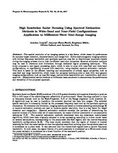
distribution lines (usually 1–10 kA). The medium voltage level of the generator terminals is 10–30 kV. The construction of busbar is usually carried out by putting together several flat rectangular bars in parallel for each phase in order to reduce thermal stresses. The spacing between the bars is made equal to their thickness for practical reasons, and this leads to skin and proximity effects. The bus ducts usually consist of aluminum or copper busbars encapsulated in a rectangular aluminum enclosure (shield), which serves for protection against mechanical stress and fire, and reduces magnetic field outside the busbars, thereby protecting electrical and electronic equipment and people’s health [1– 7]. A typical cross-section of the non-segregated three-phase highcurrent air-insulated bus duct is depicted in Fig. 1.
N d1
L2
L1 d
L3 d
b3 B
b
a1
a
b2
b1
t
t A
Figure 1. Shielded three-phase high-current bus duct of rectangular cross-section with two horizontal busbars per phase and one neutral busbar (PELPO-version II, manufactured by ELEKTROBUDOWA S. A. Katowice, Poland) The busbar’s resistance and reactance are not normally sufficiently large to affect the total impedance of a power system, and hence are not included in the calculations when establishing the short-circuit currents and reactive volt drops within a power system. The exception to this is when considering certain heavy current industrial applications such as furnaces, welding sets, or roll heating equipment for steel mills. In these cases the reactance may be required to be known for control purposes or to obtain busbar arrangements to give minimal or balanced reactances. This may be important because of its effect on both volt drop and power factor, and hence, on the generating plant’s kVA requirement per kW of load, or on the tariffs payable, where the power is purchased from outside [5]. Also, in a high-current bus duct,
Progress In Electromagnetics Research B, Vol. 51, 2013
137
where the phase busbars are connected in parallel, their impedances can cause unbalances in the total current sharing. And according to the unbalance level, over-loaded parts can lead to a heating of the structure at some points, or can be damaged by electrodynamic efforts [8]. The inductances and the effective resistances, in other words the impedances, of a shielded system of busbars at a certain frequency are closely related to the current distribution over the cross-section of each busbar generally known as “skin effect” and “proximity effect” of the nearby busbars and conductive shield. Due to electromagnetic coupling, currents in phase busbars induce eddy currents in the metal conductive shield. Hence, there is a complex electromagnetic coupling between phase busbars and the enclosure of the bus duct system. The current distribution in the busbars and the enclosure is influenced by skin and proximity effects, which need to be taken into account. Both the skin effect and proximity effect will generally cause the resistance of the busbars to increase and the inductance to decrease. If the current distribution is not uniform over the cross section of the busbar and enclosure, the computation of the resistance and inductance of busbars becomes complex due to skin and proximity effects [9, 10]. The analytical formulae are possible for round wires and tubes [11–15], very long and thin (tapes or strips) rectangular busbars [7, 16–23] or for DC cases (current densities are assumed to be uniform) [16–18, 24–30]. In other types of rectangular busbars, analytical-numerical and numerical methods must be applied [1, 4, 6, 14, 17, 18, 31–40]. These impedances can also be determined by experimental methods [41–44]. According to [9], the capacitances in the three-phase high-current bus duct systems are below 20 nF/m, and at the industrial frequency f = 50 Hz they are usually neglected [1–4, 6–11]. We also neglect them, because for the bus ducts considered in this paper we found the approximate values of capacitances to be about 20 pF/m (using FEMM). 2. INTEGRAL EQUATION The integral formulation is well known [11, 12, 24–28, 45–47] and is derived by assuming sinusoidal steady-state, and then applying the magnetoquasistatic assumption that the displacement current, jωεE, is negligible. In the case of N straight parallel conductors with length l, conductivity σ i (i = 1, 2, . . . , N ), cross section Si with sinusoidal current input function with angular frequency ω and complex value Ii flowing in the direction of Oz, the complex current density has one component along the Oz axis, that is Ji (X) = az J i (X). The component Ji (X) is independent of variable z and, in a general case,
138
Piatek et al.
depends on the self current and on the currents in the neighboring conductors (the skin and proximity effects). Then also the vector magnetic potential A(X) = az A(X), the electric field E(X) = az E(X), and the ideal conductor constitutive relation is Ji (X) = σi Ei (X). Then, the integral equation for the ith conductor is given as follows N Z J i (X) jωµ0 X J j (Y ) + (1) dvj = ui σi 4π ρXY j=1 v
j
or J i (X) jωµ0 + σi 4π
Z vi
N Z J i (Y ) jωµ0 X J j (Y ) dvi + dvj = ui ρXY 4π ρXY
(2)
j=1 v j j6=i
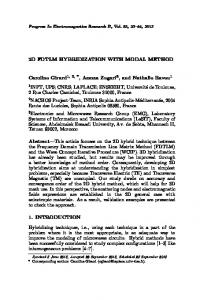
where X = X(x1 , y1 , z1 ) is the p observation point; Y = Y (x2 , y2 , z2 ) is the source point; ρXY = (x2 − x1 )2 + (y2 − y1 )2 + (z2 − z1 )2 is the distance between the observation point X and the source point Y (Fig. 2); vi and vj are the volume of the ith and the jth conductor, respectively; ui is the unit voltage drop (in V · m−1 ) across the ith conductor, and i, j = 1, 2, . . . , N . Then, by simultaneously solving (1) or (2) with the current conservation law, ∇ · J(X) = 0, the conductor current densities and the unit voltage drops can be computed. y ai Ji
ay az
ax
x
bi
aj
(s1, s5 , s 9 ) X (x1 , y1, z1) (s2 , s6 , s10)
(s3 , s 7, s11) ρXY
Y (x 2 , y2, z2)
Ii
(s4 , s 8 , s12) z
bj
Jj
Ij
Figure 2. The ith and jth conductors of a system of N parallel busbars of rectangular cross section.
Progress In Electromagnetics Research B, Vol. 51, 2013
139
In the case shown in Fig. 1 for each busbar and the enclosure, the integral equation can be written as Nj Z Nc X J i,k (X) jωµ0 X J j,l (Y ) + dvj,l = ui (3) σi 4π ρXY j=1 l=1 v j,l
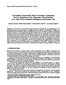
where: - Nc is the number of phases plus the neutral plus the enclosure, and i, j = 1, 2, . . . , Nc (Nc = 5), - Nj is the number of busbars belonging to one phase or the neutral or the number of rectangular plates of which the enclosure consists (usually 4), and k, l = 1, 2, . . . , Nj . 3. MULTICONDUCTOR MODEL OF THE BUSBARS In this model, each phase, neutral busbars and each plate of the enclosure are divided into several thin subbars [6, 8, 17, 23, 35, 37], as shown in Fig. 3. y Nx( i ,k ) horizontal subdivisions
∆b b
(m) S i,k
∆a
Ny( i ,k ) vertical subdivisions
a x (i,k)
Figure 3. The kth bar of the ith phase divided into Ni,k = Nx subbars.
(i,k)
Ny
This division of the kth bar of the ith phase or the neutral into subbars is carried out separately for the horizontal (Ox axis) and vertical (Oy axis) direction of their cross-sectional area. Hence, subbars are generally rectangular in the cross-section, with the width and thickness, respectively, defined by the following relations: a b ∆a = (i,k) and ∆b = (i,k) (4) Nx Ny
140
Piatek et al.
where a and b are the width and thickness of the busbar, respectively, (i,k) (i,k) and Nx and Ny are the number of divisions along the busbar width and thickness, respectively. Thus, the total number of subbars (i,k) (i,k) of the kth bar of the ith phase is Ni,k = Nx Ny , and they are numbered by m = 1, 2, . . ., Ni,k . For the lth bar of the jth phase (j,l) (j,l) or the neutral we have the total number of subbars Nj,l = Nx Ny numbered by n = 1, 2, . . . , Nj,l . All subbars have the same length l. (m) If the area Si,k = ∆a · ∆b of the mth subbar is very small and the p diagonal (∆a)2 + (∆b)2 of it is not greater than skin depth, we can neglect the skin effect and assume that the complex current density can be considered uniform, i.e., (m)
(m) J i,k
=
I i,k
(5)
(m)
Si,k
(m)
where I i,k is the complex current flowing through the mth subbar. For the enclosure we have respectively: B t t A ∆A = (5,k) , ∆B = (5,k) , ∆ty = (5,k) and ∆tx = (5,k) (6) Nx Ny Nty Ntx where A and B are the widths of two horizontal and two vertical plates of the enclosure respectively, t is their thickness and k = 1, 2. All plates have the same length l. 4. BUSBAR IMPEDANCES For the mth subbar or plate the integral Eq. (3) can be written as (m) (n) Nj Nj,l Z Nc X X J j,l (Y ) J i,k (X) jωµ0 X (n) + dvj,l = ui (7) σi 4π ρXY j=1 l=1 n=1v j,l
(n)
where vj,l is the volume of the nth subbar or plate of the lth bar or plate of the jth phase or the neutral or the enclosure. (m) Now, we can divide Eq. (7) by the area Si,k and integrate over (m)
the volume vi,k of the mth subbar or plate, obtaining the following equation: (m) (m)
Ri,k I i,k + jω
Nj Nj,l Nc X X X j=1 l=1 n=1
(m,n)
(n)
M(i,k)(j,l) I j,l = U i
(8)
Progress In Electromagnetics Research B, Vol. 51, 2013
141
where Ui is the voltage drop across all subbars of the ith phase or the neutral or the shield (they are connected in parallel), and the resistance of the mth subbar is defined by l (m) Ri,k = (9) (m) σi Si,k and the self or the mutual inductance is expressed as (m) (n) Z Z dvi,k dvj,l µ0 (m,n) M(i,k)(j,l) = (m) (n) ρXY 4πSi,k Sj,l (m) (n)
(10)
vi,k vj,l
The exact closed formulae for the self and the mutual inductance of rectangular conductor of any dimensions, including any length, are given in [24, 25] respectively. Not only do we not use the geometric mean distance here, we do not use the formula for mutual inductance between two filament wires either. The set of equations, as with (8), written for all subbars, form the following general system of complex linear algebraic equations ˆ =Z ˆ ˆI U (11) ˆ and ˆI are column vectors of the voltages and currents of where U ˆ is the symmetric matrix of self and all subbars, respectively, and Z mutual impedances (the impedance matrix) of all subbars. Assuming ˆ and ˆI are arranged as follows that vectors U {U }1 {U }2 {U }i,1 .. (i,k) ˆ , {U } = (12) U= .. i . , {U }i,k = {U i } of length N . {U }i,Ni {U }Nc {I}1 {I}2 {I}i,1 n o (n) .. ˆI= , {I}i = , {I} = I of length N (i,k)(13) .. . i,k i,k . {I} i,Ni {I}Nc ˆ can be expressed as block matrix matrix Z h i h (m,n) i h (m,n) i (m,n) Z (1,k)(2,l) ... Z (1,k)(Nc ,l) Z (1,k)(1,l) h i h i h i (m,n) (m,n) (m,n) Z (2,k)(1,l) Z (2,k)(2,l) ... Z (2,k)(Nc ,l) ˆ Z= . . . . .. .. .. .. h i h i h i (m,n) (m,n) (m,n) Z (Nc ,k)(1,l) Z (Nc ,k)(2,l) . . . Z (Nc ,k)(Nc ,l)
(14)
142
Piatek et al. (m,n)
where each submatrix [Z(i,k)(j,l) ] itself is a block matrix involving the impedances between the busbars of ith and the busbars of and jth phase: h i h i (m,n) (m,n) Z (j,1)(i,1) ... Z (j,1)(i,Ni ) h i (m,n) .. .. .. Z (i,k)(j,l) = (15) . h . . i i h (m,n) (m,n) Z (j,Nj )(i,1) . . . Z (j,Nj )(i,Ni ) ˆ are The elements of matrix Z (m) (m,n) Ri,k + jωM(i,k)(j,l) for m = n, i = j, k = l (m,n) Z (i,k)(j,l) = jωM (m,n) otherwise. (i,k)(j,l)
(16)
ˆ which is the inverse Then, we can find the admittance matrix Y, ˆ matrix of the impedance matrix Z, and expressed as h i ˆ = Y (m,n) ˆ −1 (17) Y (i,k)(j,l) = Z ˆ Then it is possible to determine the and has a similar structure to Z. current of the mth subbar of the kth bar of the ith phase or the neutral as Nj Nj,l Nc X X X (m,n) (m) I i,k = Y (i,k)(j,l) U j (18) j=1 l=1 n=1
The total current of the ith phase or the neutral is Ii =
Ni N i,k X X
(m)
I i,k
(19)
k=1 m=1
By substituting Eq. (18) into Eq. (19), we obtain Ii =
Nc X
Y i,j U j
(20)
j=1
where Y i,j =
Ni N i,k Nj Nj,l X X XX
(m,n)
Y (i,k)(j,l)
(21)
k=1 m=1 l=1 n=1
From the admittance matrix with elements given by Eq. (21), we can determine the impedance matrix of shielded three-phase system busbars with the neutral busbar as follows £ £ ¤ ¤ −1 Z = Z i,j = Y−1 = Y i,j (22)
Progress In Electromagnetics Research B, Vol. 51, 2013
143
Since each Zi,j is obtained from a matrix whose elements are comprised of information related only to construction and material, their value is not affected by the busbar current, in spite of the fact that the skin and proximity effects are taken into consideration. Impedances of busbar systems shown in Figs. 1 and 4 are characterized by a 4-by-4 impedance matrix (22). In the general case of n conductors, it is an n-by-n complex matrix. In the circuit theory, impedances Zii and Zij are called the self and mutual impedances, respectively. One should not associate them with the closed outline of the electrical circuit (according to the classical way of considering self and mutual impedances of closed circuits), but should only treat them as auxiliary quantities in the calculations of self and mutual impedances of real closed electrical circuits [11, 12]. In other words, matrix (22) allows the prediction of the system’s behavior for any connections between busbars without requiring additional field solutions. The computational model was implemented as author’s program, which links the field and circuit theory computations. Apart from determining the impedance matrix, it also allows us finding such field quantities as current density and magnetic field intensity. In addition, it takes into consideration additional impedances, e.g., the impedances grounding the enclosure. As opposed to other similar computational packages, our software uses formulae for finite-length conductors, and is especially devoted to computations for bus duct systems. 5. NUMERICAL EXAMPLES The first numerical example selected for this paper features a threephase system of rectangular busbars with one neutral busbar, whose cross-section is depicted in Fig. 1. According to the notations applied in this figure, the following geometry of the busbars has been selected: the dimensions of the phase rectangular busbars and the neutral busbars are a = 60 mm, b = b1 = 5 mm, d = d1 = 90 mm. The phase busbars and the neutral are made of copper, which has an electric conductivity of σ = 56 MS·m−1 . The frequency is 50 Hz. All phases have two busbars per phase −N1 = N2 = N3 = 2, and the neutral has one busbar — N4 = 1. The length of the busbar system is assumed to be l = 1 m and l = 3.9 m (this is the length of busbar systems investigated later in Section 6). In the numerical procedure, each phase busbar is (i,k) (i,k) divided into Nx = 30 and Ny = 5, which gives 150 subbars for each busbar. Hence, all three phases and the neutral busbars have 1050 subbars in total, which is also the total number of subbars of
144
Piatek et al.
the unshielded three-phase system. With the chosen division, each rectangular subbar has dimensions of 2 × 1 mm. This allows us to consider that the current density is uniform on the cross-surface of the subbars. The enclosure is made of aluminum, which has an electric conductivity of σ5 = 34 MS·m−1 . The dimensions of the plates of the enclosure are: A = 400 mm and B = 126 mm, their thickness is t = 3 mm. They are placed in the three-phase system with a1 = 35 mm (5,k) and b2 = 45 mm. The horizontal plate is divided into Nx = 200 and (5,k) Nty = 2, which gives 400 subbars of dimensions 2 × 1.5 mm. The (5,k)
(5,k)
vertical plate is divided into Ny = 126 and Ntx = 2, which gives 252 subbars of dimensions 2 × 1.5 mm. Hence, all four plates of the enclosure have 1304 subbars in total. The total number of all subbars of the shielded three-phase system is 2354. The results of computations are shown in Table 1. The second configuration of a three-phase busbar system, the impedances of which are investigated, is shown in Fig. 4. It has only one busbar per phase and neutral — N1 = N2 = N3 = 1 and also N4 = 1. The length of the busbar system is assumed to be l = 1 m and l = 3.9 m. In the numerical procedure, each phase busbar (i,k) (i,k) is divided into Nx = 30 and Ny = 5, which gives 150 subbars for each busbar. Hence, all three-phase and the neutral busbars have 600 subbars in total. With the chosen division, each rectangular subbar still has dimensions of 2×1 mm. The dimensions and subdivision of the enclosure are the same as in previous case. The results of computations are shown in Table 2.
N
d1
L2
L1 d
L3 d
b3 B
b
a1
a
b2
t
t A
Figure 4. Shielded three-phase high-current bus duct of rectangular cross-section with one horizontal busbar per phase and one neutral busbar (PELPO-version I, manufactured by ELEKTROBUDOWA S. A. Katowice, Poland).
Progress In Electromagnetics Research B, Vol. 51, 2013
145
Table 1. Self and mutual impedances in mΩ of unshielded (*) and shielded (**) three-phase high-current bus ducts of rectangular crosssection with a neutral busbar depicted in Fig. 1. Length l in m
Nj Ni 1 (L1) 2 (L2)
1 3 (L3) 4 (N) 1 (L1) 2 (L2) 3.9 3 (L3) 4 (N)
**
1 (L1)
2 (L2)
3 (L3)
4 (N)
*
0.038+j 0.233
0.002+j 0.126
-0.002+j 0.079
0.001+j 0.126
**
0.052+ j 0.197
0.009+j 0.108
-0.002+j 0.091
0.006+j 0.105
*
0.002+j 0.126
0.038+j 0.232
0.001+j 0.127
-0.001+j 0.079
**
0.009+j 0.108
0.052+j 0.196
0.006+j 0.105
-0.002+j 0.091
*
-0.002+j 0.079
0.001+j 0.127
0.036+j 0.234
-0.003+j 0.048
**
-0.002+j 0.091
0.006+j 0.105
0.046 +j 0.188
-0.008+ j0.089
*
0.001+j 0.126
-0.001+j 0.079
-0.003+j 0.048
0.065+j 0.240
**
0.006+j 0.105
-0.002+j 0.091
-0.008+ j0.089
0.075+j 0.194
*
0.147+j 1.250
0.005+j 0.846
-0.007+j 0.678
0.004+j 0.846
**
0.193+j 1.129
0.032+j 0.785
-0.011+j 0.723
0.022+j 0.776
*
0.005+j 0.846
0.148+j 1.246
0.003+j 0.848
-0.006+j 0.676
**
0.032+j 0.785
0.195+j 1.126
0.021+j 0.777
-0.011+j 0.723
*
-0.007+j 0.67
0.003+j 0.848
0.141+j 1.255
-0.010+j 0.573
**
-0.011+j 0.72
0.021+j 0.777
0.178+j 1.098
-0.032+j 0.714
*
0.004+j 0.846
-0.006+j 0.676
-0.010+j 0.573
0.253+j 1.276
**
0.022+j 0.776
-0.011+j 0.723
-0.032+j 0.714
0.291+j 1.117
*
* — without enclosure ; ** — with enclosure
In order to investigate the influence of the proximity effect on impedances of unshielded three-phase high-current bus ducts we also calculated impedances in the case of one rectangular busbar per phase and one neutral busbar with a vertical busbar arrangement (Fig. 5). The busbars are the same as in the previous cases and with the same distance between their axes d = d1 = 90 mm. The results of computations are shown in Table 3. We can find that for a vertical busbar arrangement the proximity effect is smaller than for the horizontal one because for the first the self resistance of the phase busbar is greater and reactance is smaller than in horizontal busbar arrangement.
146
Piatek et al.
Table 2. Self and mutual impedances in mΩ of unshielded (*) and shielded (**) three-phase high-current bus ducts of rectangular crosssection with a neutral busbar depicted in Fig. 4. Length l in m
**
Nj
1 (L1)
2 (L2)
3 (L3)
4 (N)
*
0.066+j 0.241
0.002+j 0.127
-0.001+j 0.078
0.001+j 0.127
**
0.081+j 0.202
0.010+j 0.107
-0.002+j 0.090
0.007+j 0.105
*
0.002+j 0.127
0.066+j 0.241
0.001+j 0.127
-0.001+j 0.078
*
Ni 1 (L1) 2 (L2)
1 3 (L3) 4 (N) 1 (L1) 2 (L2) 3.9 3 (L3) 4 (N)
**
0.010+j 0.107
0.081+j 0.202
0.007+j 0.105
-0.002+j 0.090
*
-0.001+j 0.078
0.001+j 0.127
0.064+j 0.242
-0.002+j 0.046
**
-0.002+j 0.090
0.007+j 0.105
0.075+j 0.194
-0.008+j 0.088
*
0.001+j 0.127
-0.001+j 0.078 -0.002+j 0.046
0.064+j 0.242
**
0.007+j 0.105
-0.002+j 0.090 -0.008+j 0.088
0.075+j 0.194
*
0.257+j 1.279
0.006+j 0.848
-0.005+j 0.673 0.003+j 0.849
**
0.311+j 1.149
0.035+j 0.783
-0.012+j 0.721 0.023+j 0.775
*
0.006+j 0.848
0.257+j 1.279
0.003+j 0.849
-0.005+j 0.67
**
0.035+j 0.783
0.311+j 1.149
0.023+j 0.775
-0.012+j 0.72
*
-0.005+j 0.673
0.003+j 0.849
0.250+j 1.284
-0.008+j 0.56
**
-0.012+j 0.721
0.023+j 0.775
0.292+j 1.119
-0.032+j 0.71
*
0.003+j 0.849
-0.005+j 0.673 -0.008+j 0.568
0.250+j 1.284
**
0.023+j 0.775
-0.012+j 0.721 -0.032+j 0.713
0.292+j 1.119
* — without enclosure; ** — with enclosure
N
L1 d1
L3
L2 d
d
b a
Figure 5. Unshielded three-phase high-current bus duct of rectangular cross-section with one vertical busbar per phase and one neutral busbar.
Progress In Electromagnetics Research B, Vol. 51, 2013
147
Table 3. Self and mutual impedances in mΩ of unshielded threephase high-current bus ducts of rectangular cross-section with a neutral busbar depicted in Fig. 5. HH
Ni Nj HHH 1 (L1) 2 (L2) 1 3 (L3) 4 (N ) HH Ni Length l in m Nj HHH 1 (L1) 2 (L2) 1 3 (L3) 4 (N ) Length l in m
1 (L1)
2 (L2)
0.06163 + j0.244 0.00037 + j0.123 0.00011 + j0.076 0.00035 + j0.123
0.00037 + j0.123 0.06163 + j0.244 0.00036 + j0.123 0.00011 + j0.076
3 (L3)
4 (N )
0.00011 + j0.076 0.00036 + j0.123 0.06160 + j0.244 0.00004 + j0.044
0.00035 + j0.123 0.00011 + j0.076 0.00004 + j0.044 0.06160 + j0.244
6. COMPARISON OF RESULTS To verify the computed impedances, we also performed computations by means of the finite element method, and also carried out suitable measurements. However, the comparison cannot be done directly, because measurements can be done only in closed current path, whereas impedances Zii and Zij are auxiliary quantities, connected with parts of current paths rather than with closed current paths, and therefore cannot be measured [44]. To avoid this handicap, one of n conductors is assumed to be a reference conductor (usually the neutral), and serves as the return path. In the case shown in Fig. 6(a), a single phase current, Ii , is injected into the i-N loop. The complex voltage along busbars i, j and N , respectively, are as follows: U i = Z ii I i + Z iN I N = (Z ii − Z iN )I i U j = Z ji I i + Z jN I N = (Z ji − Z jN )I i U N = Z N i I i + Z N N I N = (Z N i − Z N N )I i
(23a) (23b) (23c)
The voltage between terminals i-N is: U iN = U i − U N = (Z ii − Z iN − Z N i + Z N N )I i
(24a)
and the voltage between terminals j-N is given by U jN = U j − U N = (Z ji − Z jN − Z N i + Z N N )I i
(24b)
148
Piatek et al. U1
1 U lN
I1= 0
Z 11 Ui
1 I1= 0 Z li
Z lj
Ii
Z ii Uj
j I j= 0 U jN
Z jj UN
N IN =-Ii
ZNN
(a)
U lN
z 11 z li
z lj
i
i U iN
Z lN
Ii
z ii
U iN
Z ij
z ij
j Z jN
Z iN
Ij = 0 U jN
z jj
N IN=-I i
(b)
Figure 6. Circuit model with i-N current injection: (a) with the self Z ii and mutual Z ij impedances, (b) with the reduced self z ii and mutual z ij impedances. Now we can assume the neutral busbar to be the reference conductor and define the self impedance of loop i-N as U (25a) z ii = iN = Z ii − Z iN − Z N i + Z N N Ii and the mutual inductance between loops i-N and j-N as U jN z ji = = Z ji − Z jN − Z N i + Z N N (25b) Ii Consequently, we receive an (n−1)-by-(n−1) new complex matrix, the elements of which are zii and zji . This can be called the reduced matrix of self and mutual impedances. In our case we have a 3-by-3 reduced impedance matrix " # z 11 z 12 z 13 z = z 21 z 22 z 23 (26) z 31 z 32 z 33 Such impedances can be measured via voltage and current measurement, as shown in Fig. 6(b). Impedances zij of the busbar systems shown in Figs. 1 and 4 were measured in the laboratory on an experimental setup (Fig. 7). The busbar systems under test were 4.6 m long, and terminated at one end by a short connector. The length of the enclosure was 4 m. The other dimensions of the investigated busbar system were the same as those given in Section 5. In the measurements, a single-phase current of 1 kA was injected into a test system by a special AC current source. The
Progress In Electromagnetics Research B, Vol. 51, 2013
149
Figure 7. Laboratory stand for impedance measurements in threephase busbar system: 1 — busbars, 2 — enclosure (open top cover), 3 — supply, 4 — Rogowski coil, 5 — digital voltmeter, 6 — digital phase meter, 7 — digital scope. current was measured via a flexible Rogowski coil with an accuracy of ±1%. The voltages were measured via a digital voltmeter with an accuracy of ±0.1%. The phase shift between the voltage and the current was measured via a digital phase meter with an accuracy of ±1%. The experiments were performed under a 50 Hz sinusoidal supply. In order to avoid the influence of end connections, the voltage drops were measured considering only the central portion of the system, i.e., the voltage drops were obtained from the difference between the voltages measured at two difference positions along the busbars at a distance of 3.9 m between them inside the enclosure, and at a distance of 0.35 m from the end of the busbar. To calculate the reduced impedance matrix (26) the voltage RMS, current RMS and phase shift between their instantaneous values were measured. The measurements were performed for four arrangements of the busbar system: shielded and unshielded three-phase high-current bus duct with two and one busbars per phase, and one neutral busbar. The measurements were repeated several times, and the average value of the impedance matrix is presented in Tables 4 and 5 in the third subrows. The elements of matrix (26) computed from our integral equation method (IEM), determined from (22) via Eqs. (25a) and (25b), are written down in the first subrows. We found that the measured values of resistances and reactances are very close to the computed ones. In general, the relative error does not exceed 5% for unshielded bus ducts and 10% for shielded ones. It is noticeable that the measured values are slightly greater than the computed ones, especially for the shielded bus ducts. The increased
150
Piatek et al.
Table 4. Reduced self and mutual impedances in mΩ of unshielded (*) and shielded (**) three-phase high-current bus ducts of rectangular cross-section with a neutral busbar depicted in Fig. 1. Length l in m
j
** Method
i
IEM computations
*
FEM computations
Measurements
1 (L1)
IEM computations
**
FEM computations
Measurements IEM computations
* 3.9
1 (L1)
2 (L2)
3 (L3)
*
FEM computations
Measurement
2 (L2)
IEM computations
**
FEM computations
Measurements IEM computations
*
FEM computations
Measurements
3 (L3)
IEM computations
**
FEM computations
Measurements
0.391+j 0.834 0.261+j 0.600 0.251+j 0.535 0.391+j 0.801 0.262+j 0.589 0.252+j 0.524 0.410+j 0.837 0.271+j 0.626 0.260+j 0.557 0.443+j 0.693 0.438+j 0.671 0.459+j 0.717 0.261+j 0.600 0.262+j 0.589 0.267+j 0.629 0.313+j 0.403 0.313+j 0.406 0.346+j 0.441
0.313+j 0.403 0.312+j 0.406 0.346+j 0.447 0.414+j 1.170 0.417+j 1.125 0.430+j 1.172 0.511+j 0.798 0.505+j 0.782 0.557+j 0.866
0.289+j 0.349 0.288+j 0.350 0.320+j 0.375 0.273+j 0.875 0.275+j 0.852 0.275+j 0.904 0.357+j 0.458 0.354+j 0.464 0.392+j 0.505
0.251+j 0.535 0.273+j 0.875 0.414+j 1.385 0.252+j 0.524 0.275+j 0.852 0.417+j 1.329 0.253+j 0.561 0.280+j 0.880 0.415+j 1.394 0.289+j 0.349 0.357+j 0.458 0.534+j 0.788 0.288+j 0.350 0.354+j 0.464 0.527+j 0.772 0.317+j 0.365 0.393+j 0.507 0.587+j 0.797
* — without enclosure; ** — with enclosure
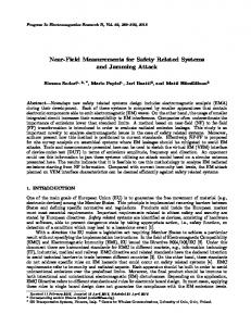
Figure 8. The finite element mesh used in FEMM computations.
Progress In Electromagnetics Research B, Vol. 51, 2013
151
Table 5. Reduced self and mutual impedances in mΩ of unshielded (*) and shielded (**) three- phase high-current bus ducts of rectangular cross-section with a neutral busbar depicted in Fig. 4. Length l in m
j i
**
Method
1 (L1)
2 (L2)
3 (L3)
*
IEM computations FEM computations
**
IEM computations FEM computations
*
IEM computations FEM computations
**
IEM computations FEM computations
0.501+j 0.864 0.500+j 0.852 0.504+j 0.865 0.556+j 0.718 0.552+j 0.717 0.599+j 0.773 0.258+j 0.609 0.258+j 0.598 0.261+j 0.640 0.315+j 0.406 0.313+j 0.409 0.347+j 0.444 0.249+j 0.539 0.249+j 0.527 0.261+ j 0.551 0.289+j 0.351 0.288+j 0.351 0.317+j 0.379
0.258+j 0.609 0.258+j 0.598 0.263+j 0.637 0.315+j 0.406 0.313+j 0.409 0.342+j 0.444 0.519+j 1.218 0.518+j 1.195 0.544+j 1.231 0.628+j 0.827 0.621+j 0.834 0.680+j 0.894 0.267+j 0.893 0.266+j 0.871 0.275+j 0.927 0.360+j 0.460 0.356+j 0.467 0.398+j 0.510
0.249+j 0.539 0.249+j 0.527 0.252+j 0.560 0.289+j 0.351 0.288+j 0.351 0.320+j 0.368 0.267+j 0.893 0.266+j 0.871 0.279+j 0.928 0.360+j 0.460 0.356+j 0.467 0.387+j 0.503 0.517+j 1.433 0.516+j 1.399 0.518+j 1.144 0.649+j 0.811 0.644+j 0.818 0.718+j 0.846
*
Measurements
1 (L1)
Measurements
3.9
Measurements
2 (L2)
Measurements *
IEM computations FEM computations
**
IEM computations FEM computations
Measurements
3 (L3)
Measurements
* — without enclosure; ** — with enclosure
values probably come from some extra parts that are not included in the computational model, such as aluminum supports. Also, the shield is made of profiled sheet metal, which does not correspond the computational cross-section exactly. Apart from experimental verification, computer simulations for bus bar system impedances were also performed with the aid of the commercial FEMM software [48], using two-dimensional finite elements. Fig. 8 shows the computational finite element mesh with about 15000 nodes. For the purposes of comparison, first the impedances Zij of four bus bar systems, described in Section 5, were calculated, and then the reduced impedances zij were found via Eqs. (25a) and (25b). The results are presented in Tables 4 and 5 in the second subrows. They are very similar to those obtained by means of IEM. The values of resistance differ up to 1%, but the discrepancy is often much smaller. As for reactances, the difference is up to 4%, but usually it is below
152
Piatek et al.
2%. The most probable reason is that FEMM performs 2D field computations whereas our method uses the formulae for finite-length conductors. 7. CONCLUSIONS A novel approach to the solution of impedances of high-current bus ducts of rectangular cross-section is presented in this paper. The proposed approach combines Partial Element Equivalent Circuit (PEEC) method with the exact closed formulae for AC self and mutual inductances of rectangular conductors of any dimensions, which allows the precise accounting of skin and proximity effects. Complete electromagnetic coupling between phase busbars and the neutral busbar is also taken into account. As Tables 1 and 2 show, self and mutual impedances of the investigated bus ducts depend strongly on the presence of the enclosure. In general, the induced eddy currents in the enclosure cause the self resistance of the busbars to increase and the self inductance to decrease when compared to the case without enclosure. In addition, impedances of a three-phase busbar system are not purely proportional to its length. The resistances and reactances for l = 3.9 m are expected to be about 3.9 times greater than the corresponding ones for l = 1 m. This is true for resistances, but the reactances for l = 3.9 m are about 5–10 times greater than for l = 1 m. Our numerical method is validated by the commercial FEM software and laboratory measurements. The skin, proximity and eddy currents effects are taken into consideration. The results from the measurements indicate that the our numerical method can be used to predict the impedance of any such rectangular busbar system with good accuracy. Both busbar separation and enclosure have great influence on its impedance. The model predictions are found to be in very good agreement with measurements. The proposed method allows us to calculate the phase impedances of a set of parallel rectangular busbars of any dimensions including any length. For the industrial frequency, a 100% increase in the number of total subbars changes the impedances less than 0.02%. The model is strikingly simple, and from a logical stand-point can be applied in general to conductors of any cross-section, whereas many conventional methods, being much more complicated, require a greater or lesser degree of symmetry. From the practical stand-point of the calculations involved, the model requires the solution of a rather large set of linear simultaneous equations. However, this solution is well within the ability range of existing computers.
Progress In Electromagnetics Research B, Vol. 51, 2013
153
ACKNOWLEDGMENT This work was supported by the National Science Centre, Poland, under Grant No. N N511 312540. REFERENCES 1. Salinas, E., “Conductive and ferromagnetic screening of 50 Hz magnetic field from a three-phase system of busbars,” Journal of Magnetism and Magnetic Materials, No. 226–230, 1239–1241, 2001. 2. Ducluzaux, A., “Extra losses caused in high current conductors by skin and proximity effects,” Schneider Electric, Cahier Technique, No. 83, 1983. 3. Du, Y. and J. Burnett, “Power-frequency magnetic shielding of heavy-current conductors by rectangular shields, IEE Proc. — Gener. Transm. Distrib., Vol. 146, No. 5, 223–228, 1999. 4. Koroglu, S., P. Sergeant, and N. Umurkan, “ Comparison of analytical, finite element and neural network methods to study magnetic shielding,” Simulation Modelling Practice and Theory, No. 18, 206–216, 2010. 5. Copper Development Association, Copper for Busbars, 2001, ava ilable online at: http://www.cda.org.uk/Megab2/elecapps/pub2 2/index.htm. 6. Saraj˘cev, P. and R. Goi˘c, “Power loss computation in high-current generator bus ducts of rectangular cross-section,” Electric Power Components and Systems, No. 38, 1469–1485, 2010. 7. Chiampi, M., D. Chiarabaglio, and M. Tartaglia, “A general approach for analyzing power busbar under AC conditions,” IEEE Trans. on Magn., Vol. 20, No. 6, 2473–2475, 1993. 8. Clavel, E., J. Roudet, and A. Foggia, “Electrical modeling of transformer connecting bars,” IEEE Trans. on Magn., Vol. 38, No. 2, 1378–1382, 2002. 9. Sigg, H. J. and M. J. O. Strutt, “Skin effect and proximity effect in polyphase systems of rectangular conductors calculated on an RC network,” IEEE Trans. on Power Apparatus and Systems, Vol. PAS-89, No. 3, 470–477, 1970. 10. Guo, J., A. W. Glisson, and D. Kajfez, “Analysis of resistance and internal reactance in systems of parallel conductors,” Int. J. ¨ Vol. 52, No. 2, 57–64, 1998. Electron. Commun. AEU,
154
Piatek et al.
11. Pi¸atek, Z., Impedances of Tubular High Current Busducts, Polish Academy of Sciences, Warsaw, 2008. 12. Pi¸atek, Z., “Self and mutual impedances of a finite length gas insulated transmission line (GIL),” Elec. Pow. Syst. Res., No. 77, 191–203, 2007. 13. Lovri´c, D., V. Boras, and S. Vujevi´c, “Accuracy of approximate formulas for internal impedance of tubular cylindrical conductors for large parameters,” Progress in Electromagnetics Research M, Vol. 16, 171–184, 2011. 14. Fazljoo, S. A. and M. R. Besmi, “ A new method for calculation of impedance in various frequencies,” 1st Power Electronic & Drive Systems & Technologies Conference (PEDSTC), 36–40, February 17–18, 2010. 15. Ametani, A., “Approximate method for calculating the impedance of multiconductors with cross section of arbitrary shapes,” Electrical Engineering in Japan, Vol. 111, No. 2, 117–123, 1992. 16. Kazimierczuk, M. K., High-frequency Magnetic Components, J. Wiley & Sons, Chichester, 2009. 17. Paul, C. R., Inductance: Loop and Partial, J. Wiley & Sons, New Jersey, 2010. 18. Paul, C. R., Analysis of Multiconductor Transmission Lines, J. Wiley & Sons, New Jersey, 2010. 19. Silvester, P., “AC resistance and reactance of isolated rectangular conductors,” IEEE Trans. on Power Apparatus and Systems, Vol. PAS-86, No. 6, 770–774, June 1967. 20. Goddard, K. F., A. A. Roy, and J. K. Sykulski, “Inductance and resistance calculations for isolated conductor,” IEE Pro. — Sci. Meas. Technol., Vol. 152, No. 1, 7–14, January 2005. 21. Goddard, K. F., A. A. Roy, and J. K. Sykulski, “Inductance and resistance calculations for a pair of rectangular conductor,” IEE Pro. — Sci. Meas. Technol., Vol. 152, No. 1, 73–78, January 2005. 22. Chen, H. and J. Fang, “Modeling of impedance of rectangular cross-section conductors,” IEEE Conference on Electrical Performance of Electronic Packaging, 159–162, 2000. 23. Zhihua, Z. and M. Weiming, “AC impedance of an isolated flat conductor,” IEEE Trans. on Electromagnetic Compatibility, Vol. 44, No. 3, 482–486, 2002. 24. Pi¸atek, Z. and B. Baron, “Exact closed form formula for self inductance of conductor of rectangular cross section,” Progress In Electromagnetics Research M, Vol. 26, 225–236, 2012. 25. Pi¸atek, Z., et al., “Exact closed form formula for mutual
Progress In Electromagnetics Research B, Vol. 51, 2013
26. 27. 28.
29. 30. 31. 32. 33. 34. 35. 36.
37.
155
inductance of conductors of rectangular cross section,” Przegl¸ad Elektrotechniczny (Electrical Review), R. 89, No. 3a, 61–64, 2013. Pi¸atek, Z., et al., “Self inductance of long conductor of rectangular cross section,” Przegl¸ad Elektrotechniczny (Electrical Review), R. 88, No. 8, 323–326, 2012. Pi¸atek, Z., et al., “Mutual inductance of long rectangular conductors,” Przegl¸ad Elektrotechniczny (Electrical Review), R. 88, No. 9a, 175–177, 2012. Broyd´e, F., E. Clavelier, and L. Broyd´e, “A direct current per-unit-length inductance matrix computation using modified partial inductance,” Proc. of the CEM 2012 Int. Symp. on Electromagnetic Compatibility, Rouen, April 25–27, 2012. Hoer, C. and C. Love, “Exact inductance equations for rectangular conductors with application to more complicated geometries,” J. Res. NBS, Vol. 69C, No. 2, 127–137, 1965. Zhong, G. and C. K. Koh, “Exact form formula for mutual inductance of on-chip interconnects,” IEEE Trans. on Circ. and Sys., I: FTA, No. 10, 1349–1353, 2003. Antonini, G., A. Orlandi, and C. R. Paul, “Internal impedance of conductor of rectangular cross section,” IEEE Trans. on Microwave Theory and Tech., Vol. 47, No. 7, 979–984, 1999. Canova, A. and L. Giaccone, “Numerical and analytical modeling of busbar systems,” IEEE Trans. on Power Delivery, Vol. 24, No. 3, 1568–1577, July 2009. Weeks, W. T., et al., “Resistive and inductive skin effect in rectangular conductors,” IBM J. Res. Develop., Vol. 23, No. 6, 652–660, November 1979. Barr, A. W., “Calculation of frequency dependent impedance for conductor of rectangular cross section,” AMP J. of Technology, Vol. 1, 91–100, November 1991. Baron, B., et al., “Impedance of an isolated rectangular conductor,” Przegl¸ad Elektrotechniczny (Electrical Review), R. 89, No. 4, 278–280, 2013. Comellini, E., A. Invernizzi, and G. Manzoni, “A computer program for determining electrical resistance and reactance of any transmission line,” IEEE Trans. on Power Apparatus and Systems, Vol. PAS-92, 308–314, 1973. Tsuboi, K., M. Tsuji, and E. Yamada, “A simplified method of calculating busbar inductance and its application for stray resonance analysis in an inverter DC link,” Electrical Engineering in Japan, Vol. 126, No. 3, 49–63, 1999.
156
Piatek et al.
38. Angi, H., M. Weiming, and Z. Zhihua, “ New numerical methods of computing internal inductance of conductor of rectangular cross-section,” Asia-Pacific Symposium on Electromagnetic Compatibility and 19th International Zurich Symposium on Electromagnetic Compatibility, 674–677, 2008. 39. Matsuki, M. and A. Matsushima, “Improved numerical method for computing internal impedance of a rectangular conductor and discussions of its high frequency behavior,” Progress In Electromagnetics Research M, Vol. 23, 139–152, 2012. 40. Matsuki, M. and A. Matsushima, “Efficient impedance computation for multiconductor transmission lines of rectangular cross section,” Progress In Electromagnetics Research B, Vol. 43, 373– 391, 2012. 41. Battauscio, O., M. Chiampi, and D. Chiarabaglio, “Experimental validation of a numerical model of busbar systems,” IEE Proceedings — Generation, Transmission and Distribution, 65– 72, 1995. 42. Birtwistle, D. and P. Pearl, “Measurement of impedance, power loss and current distribution in three-phase busbars,” J. of Electrical and Electronics Engineering, Australia — IE Aust. & IREE Aust., Vol. 8, No. 1, 37–46, 1988. 43. Du, J., J. Burnett, and Z. C. Fu, “Experimental and numerical evaluation of busbar trunking impedance,” Electric Power Systems Research, No. 55, 113–119, 2000. 44. Battauscio, O., et al., “Numerical and experimental evaluation of magnetic field generated by power busbar systems,” IEE Proc. — Gener. Transm. Distrib., Vol. 143, No. 5, 455–460, 1996. 45. Konrad, A., “Interodifferential finite element formulation of twodimensional steady-state skin effect problems,” IEEE Trans. on Magn., Vol. MAG-18, 284–292, 1982. 46. Deeley, E. M. and E. E. Okon, “An integral method for computing the inductance and A.C. resistance of parallel conductors,” International Journal for Numerical Methods in Engineering, Vol. 12, 625–634, 1978. 47. Kamon, M., M. J. Tsuk, and J. K. White, “FASTHENRY: A multipole-accelerated 3-D inductance extraction program,” IEEE Trans. on Microwave Theory and Techniques, Vol. 42, No. 9, 1750– 1758, September 1994. 48. Meeker, D., Finite Element Method Magnetics, version 4.2 (April 11, 2012, Mathematica Build), http://www.femm.info.