Mecánica Computacional Vol XXXIII, págs. 3195-3207 (artículo completo) Graciela Bertolino, Mariano Cantero, Mario Storti y Federico Teruel (Eds.) San Carlos de Bariloche, 23-26 Setiembre 2014
NUMERICAL METHODS USED IN CONDOR CODE Eduardo A. Villarinoa a
Nuclear Engineering Deparment. INVAP SE. Av Luis Piedrabuena 4950, San Carlos de Bariloche, Rio Negro Argentina,
[email protected], http://www.invap.com.ar
Keywords: Cell Code, Reactor Physics and Transport Methods. Neutronic calculations. Abstract. INVAP uses computational tools to predict the behavior of the reactor to be built. Every new reactor needs increasingly detailed analysis from different points of view, as nuclear safety and fulfillment of user requirements (flux and production levels, spectra requirements, perturbations, etc). Furthermore, this analysis must be modeled with a consistent level of detail from all the engineering variables. INVAP has been on continuous development of the calculation system used for design and optimization of nuclear reactors. The calculation codes have been polished and enhanced with new capabilities as they were needed for the reactor design, improving its safety, fuel economy and performance. Nowadays, this calculation line is divided in two main codes: Cell (CONDOR) and Core (CITVAP) codes. The homogenized and condensed macroscopic Cross Section (XS) is one of the main parameters used as interface between both codes; which are calculated by the Cell code and they are used as input by the Core code. The present work summarizes the different theories, algorithms and numerical approaches used by CONDOR to generate the required parameters. The description covers all the calculation stages from the geometrical input up to the generation of the output parameters, describing the different methods used in the different stages.
Copyright © 2014 Asociación Argentina de Mecánica Computacional http://www.amcaonline.org.ar
3196
1
E.A. VILLARINO
INTRODUCTION
Figure 1 shows INVAP´s calculation line (Mochi, 2011), which has been used by INVAP and several of its customers for the design, optimization and follow-up of several reactors throughout the world obtaining optimal results, like RA-6, NUR, RA-8, ETRR2, OPAL, CAREM, CNA-II, etc. These codes are also used by nuclear engineering students, master’s and doctoral thesis students of the Balseiro Institute, performing a large number of calculations for different reactor types such as MTR, PWR, BWR, PHWR, TRIGA, FBR, ADS and Homogeneous reactors.
Figure 1: INVAP Calculation Line
CONDOR (Villarino, 2002) is the cell code used for the fuel assembly (FA) analysis and the calculation of the homogenized and condensed macroscopic XS. It was designed to properly calculate the FA at cell level using low calculation time. The user interfaces (input and output) are flexible and easy to use and were specially developed to minimize user errors and allow easy integration with other calculation codes.
Copyright © 2014 Asociación Argentina de Mecánica Computacional http://www.amcaonline.org.ar
Mecánica Computacional Vol XXXIII, págs. 3195-3207 (2014)
3197
CONDOR can use one of two transport methods for the calculation of the flux in the system under analysis: Collision Probabilities method (CP) and Heterogeneous Response Method (HRM). Regarding the geometry modeling capabilities, CONDOR can model the system in four different geometries: 1D-Slab, 1D-Cylindrycal, 2D-Cylindrycal, and 2D-General. The program is divided in modules and each of them has a specific task. The description of the different algorithms used by the program will be given following those modules, some of them are not relevant from the numerical method point of view, but they will provide a general overview of the CONDOR code and will help the reader understand in a better way the CONDOR capabilities. 2
CONDOR GENERAL DESCRIPTION
CONDOR was initially developed for Atucha and Embalse NPP FA’s analysis (Villarino 1990a; Villarino 1992), but during its development, the capabilities to model CAREM FAs were added and several validations were done against VVER reactors in the frame of the CAREM proyect (Villarino, Lecot 1996). Additional capabilities to model MTR FAs were added: first adding slab geometry and later the Heterogeneous Response Method (Villarino and Stamm’ler, 1984, Villarino, Stamm’ler, Ferri & Casal 1992). During this process several methods and algorithms were added to improve not only the calculation capabilities but the overall performance of the CONDOR code. To model different geometries CONDOR code uses different transport and resonant methods, which are presented in Table 1, identifying its characteristic for the available geometries. Geometry 1D-Slab 1D-Cylindrical
Transport Method CP CP
Resonant Treatment Integral Method Integral Method
2D-Cylindrical
CP
Integral Method
2D-General
HRM
Sub Group Method
Resonant Region Slab Regions Pin and annular regions Pin and annular regions in cluster with rings or polygonal distribution Any geometry
Table 1: CONDOR geometry and resonant treatment methods
Some examples of the geometry modeling capabilities are presented in the following sections, identifying the method used together with main considerations. 2.1 1D-Slab Geometry For 1-D slab geometry, a set of different thicknesses and compositions are allowed and boundary conditions (left and right) are introduced (i.e. reflective, white, free). As an example, Figure 2 shows a 1D-Slab model that consists of three materials divided in several zones.
Figure 2: 1D-Slab model.
Copyright © 2014 Asociación Argentina de Mecánica Computacional http://www.amcaonline.org.ar
3198
E.A. VILLARINO
2.2 1D-Cylindrical Geometry To model 1-D cylindrical cases, CONDOR, allows defining a set of different radii and compositions and a boundary condition is introduced (i.e. reflective, white, free). As an example, Figure 3 shows a 1D-Cylindrical case.
Figure 3: 1D-Cylindrical model.
2.3 2D-Cylindrical Geometry For 2-D cylindrical geometry that consists of a set of pins, CONDOR assembles the geometry of the system as follows: • Define the region of the system without pins or rods. For example the coolant, moderator, and structural materials. This definition is done for annular or regular polygons regions. • Define the type of pins or rods and their distribution. This distribution is only valid for annular or regular polygon rings. • The pin or rod distribution overlaps the non pin definition. Only one boundary condition is introduced (i.e. reflective, white, free), as an example the Figure 4 shows a VVER, ATUCHA and PWR 2D-Cylindrical models.
Figure 4: 2D-Cylindrical models.
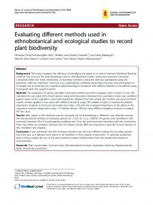
2.4 2D-General Geometry Finally, CONDOR allows the definition of general 2-D geometries. For this cases, the whole system, usually a FA, is divided into space elements, were the number of geometrically different space elements is frequently small. These space elements are coupled to model the whole system. Different boundary conditions can be introduced in each external segment of the system. In Figure 5 VVER, PWR and MTR FAs are shown, including the space element types of each of them. Copyright © 2014 Asociación Argentina de Mecánica Computacional http://www.amcaonline.org.ar
Mecánica Computacional Vol XXXIII, págs. 3195-3207 (2014)
3199
Figure 5: 2D-General models.
3
USER INPUT
This module is not important from methodology point of view, but it is important from one of the concepts of the INVAP calculation line: User integration. The CONDOR input is handled by the Free format package (Villarino, 2010), which eases the input preparation, for example using parameters and operating with them during input processing. This package is also used by other programs included in INVAP calculation line like HGEO, ARCANE, etc. 4
PROGRAM INPUT
This module converts user input to program input (for example radii to volumes, or density and weight fractions to numerical densities, isotope and material expansion due burnup or resonant effects, etc). It is not important from a methodology point of view, but adds several important user friendly capabilities to the code. Vector algebra is used to deal with the complex geometries to be handled in the 2D-general geometry cases. Accordingly it is used for volume calculation, intersections between segments to expand a user segment into program segments, removing segments hidden by rods or pins, etc. 5
RAY TRACING.
This module is dedicated to perform the ray tracing to be used for the CP calculation. Only geometrical information is processed in such a way to allow in a following module the calculation of the group dependent CPs. It means that thicknesses in cm and its belonging meshes are saved. In a following step, the thicknesses in cm are converted to mean free paths through the group dependent total XS, allowing the calculation of the CP. As an example, Figure 6 shows a Chord, identifying the information needed for the CPs calculation (i.e. the thicknesses).
Copyright © 2014 Asociación Argentina de Mecánica Computacional http://www.amcaonline.org.ar
3200
E.A. VILLARINO
Figure 6: Ray tracing sample for 2D General geometry.
5.1 1D-Slab Geometry For 1-D slab geometry, the storage of the ray tracing data is only implemented to preserve the general structure of the code, as far as for 1-D cases the calculation of the CPs does not need a numerical integration in geometry (Stamm´ler and Abbate, 1983). 5.2 1D-Cylindrical Geometry As for the 1-D slab geometry, for 1-D cylindrical geometry the storage of the ray tracing data is only included to preserve the general structure of the program. The main difference is that the calculation of the CP needs 1D-dimensional numerical integration (over radii coordinate), which is performed using a gauss quadrature (Stamm´ler and Abbate, 1983). 5.3 2D-Cylindrical Geometry For this case, the calculation of the CP needs 2D-dimensional numerical integration (Carlvik, 1965): over radii and azimuthal coordinates. This numerical integration is done as follows: • Azimuthal integration: It is done over only the symmetry angle of the system, where a given number of equi-spaced integration angles are used. • Radii integration: A smart analysis of the radii dependence of the system is carried out, to determine a set of macro-bands (Villarino, Stamm´ler, Casal & Ferri, 1992; Villarino, 1990a) where a set of equi-spaced rays are defined. The main characteristic of these macro-bands is that the CP inside each macro-band is continuous in function of the radii. The surface and volumes of the meshes are integrated and compared with the real values. This information is used in two different ways: • If the differences are bigger than a given value the ray tracing scheme is repeated with a bigger number of rays or chords, improving the geometrical integration. • Independently of the final precision, the ray tracing data (thicknesses and weights) are modified to preserve the real volumes and surfaces of the system. 5.4 2D-General Geometry For general 2-D geometry CP calculations, a 2D-dimensional numerical integration (over radii and azimuthal coordinates) is compulsory. This numerical integration is done in a similar way that in 2D-Cylindrical Geometry. Copyright © 2014 Asociación Argentina de Mecánica Computacional http://www.amcaonline.org.ar
Mecánica Computacional Vol XXXIII, págs. 3195-3207 (2014)
3201
The calculation of the CP are divided is region to region, surface to region and surface to surface integration. This is done using two different ray tracing schemes: Volume and Surface integration. In both integrations the macro-band algorithm and the normalization of the volumes and surface are used as in the previous geometry. 6
MACROSCOPIC CROSS SECTION
The calculation of the macroscopic XS is carried out using the microscopic XS given in the nuclear XS library and the burnup and state dependent numerical densities of the materials. The exception of this calculation is the in the resonant groups and for the resonant isotopes. In such cases CONDOR uses different approaches depending in the geometry under analysis. 6.1 1D-Slab Geometry, 1D-Cylindrical Geometry and 2D-Cylindrical Geometry In these geometries there are two different options: • Integral resonant method (Stamm´ler & Abbate, 1983). The escape equivalent XS is calculated using a two term rational approximation for the slab, pin or annular resonant regions (Villarino, 1992). • Dancoff factor calculation can be used to calculate the escape equivalent XS. This option requires a transport calculation per resonant group or for a given resonant group. After the calculation of the equivalent escape XS is calculated, the interaction between resonant absorbers and the removal correction factor are evaluated with the same methodology as the integral resonant method. 6.2 2D-General Geometry For this geometry cases, the methods described in last section cannot be applied and another approach must be implemented. Thus, for general 2-D geometries the subgroup resonant method is used (Ibarra 1990; Notari and Garrafo 1986). The implementation of this method in the CONDOR code basically consists of the calculation of the lethargy dependent escape XS (through the subgroup absorption XS). It means that a given number of transport calculations are needed. Currently, CONDOR uses 3 transport calculations, when condensation option is used, or 3 transport calculation per resonant group without this option. When this escape XS is calculated a similar approach as the integral resonant method can be used to deal the interaction between resonant absorbers, and the removal XS correction factor. 7
COLLISION PROBABILITIES AND RESPONSE FLUXES
The data needed for the flux calculation are the response fluxes. For all the geometries, these data are calculated by two different methods: • Directly from the CPs. In this case the CP needs to be calculated and depends on the geometry of the system. A new algorithm to calculate the CPs was applied reducing the calculation time (Villarino 1990a, Weiss 1990). • For a given system, it is possible to calculate response fluxes from previously calculated values if the total XSs have small perturbations (Villarino and Stamm’ler 1996; Wio 1984). This variational method does not depend on the modeling geometry, but due to its implementation, it is conceptually different for the 2D-General geometry. The following sections explain the differences between the calculation of the CPs and
Copyright © 2014 Asociación Argentina de Mecánica Computacional http://www.amcaonline.org.ar
3202
E.A. VILLARINO
Response Fluxes. 7.1 1D-Slab Geometry CP calculation. In this geometry, the CPs are calculated using the ray tracing data provided previously, where the structure of those data is similar to 1D-Cylindrical and 2D-Cylindrical geometries. Basically the region to region CPs are calculated together with the region to surface and the surface to surface CPs. 7.2 1D-Cylindrical Geometry CP calculation. In this geometry, the CP are calculated using the ray tracing data provided previously, where the structure of those data is also similar to 1D-Slab and 2D-Cylindrical geometries. Only region to region CPs are calculated, and the remaining CPs are calculated based on the balance equations of the CPs. 7.3 2D-Cylindrical Geometry CP calculation. In this geometry, the CP are calculated using the ray tracing data provided previously, where the structure of those data is similar to 1D-Slab and 1D-Cylindrical geometries. Only region to region CPs are calculated, and the remaining CPs are calculated based on the balance equations of the CPs. 7.4 2D-General Geometry CP calculation. In this geometry, the CPs are calculated using the ray tracing data provided previously. As it was explained in section 5.4, this ray tracing data is divided in volume and surface integration. The volume ray-tracing data is used for the region to region CPs (which do not have angular dependence), and the surface ray tracing data is used for surface to region and surface to surface CPs (which can have angular dependence). This division calculates numerically more stable CPs, requiring less computational effort for the numerical integration. 7.5 Response fluxes calculation from CP. When CPs are numerically integrated, CONDOR performs a normalization of those variables to preserve the five balance equations of the CP. (Villarino, 1990b), then response fluxes can be calculated. 7.6 Variational Method for Response fluxes calculation. If a given system was previously calculated, it is possible to analyze the difference in the total XS between previous and actual case, and if this difference is smaller than a given value, the variational method can be used (Villarino and Stamm’ler 1996, Wio 1984). In CONDOR, this analysis is done by group taking in to account small differences in the XS due to burnup effects. Additionally to this burnup dependent analysis and in the case of the HRM method, it is possible to do similar comparison between two geometrically equal space elements (Villarino and Stamm’ler 1996) and apply this variational method if the differences in the total XS are smaller than a given value.
Copyright © 2014 Asociación Argentina de Mecánica Computacional http://www.amcaonline.org.ar
Mecánica Computacional Vol XXXIII, págs. 3195-3207 (2014)
8
3203
MULTIGROUP CALCULATION
The energy dependence of the flux is carried out in this module. Normally this method requires an iterative process for the convergence of the energy dependence (outer iterations) and iterative process for the convergence of the spatial flux for a given group (inner iterations). The CP method does not need inner iterations, but the HRM needs it to solve the spatial distribution of the coupling currents between the space elements. To improve the outer iteration process different acceleration techniques were implemented in CONDOR code (Stamm´ler & Abbate 1983): • Over-relaxation factor over fission source and thermal fluxes. • Thermal iterations over two different levels, depending of the up-scattering source. • Fundamental Rebalancing method. When HRM is used, CONDOR performs the iterative process between elements, ordering the space elements by the total out current of each element. It means that CONDOR starts to iterate from the elements with higher coupling with its neighbors. As far as CONDOR code is used in several reactor designs, all optimization algorithms are analyzed in order to avoid numerical concerns. As an example, when CONDOR is used for Fast Reactors calculations, most of the thermal acceleration algorithms produce numerical issues. For this reason CONDOR automatically detects it through the down-scattering source if those methods can be used or not, disabling them if not and using only the over-relaxation factor on the fission source. 9
CRITICAL SPECTRA
CONDOR performs burnup and condensation of the XSs using critical spectra. This spectra is calculated for a homogeneous infinite system, using B1 (Stamm´ler & Abbate 1983) or Diffusion theory. The heterogeneous system is homogenized with the transport infinite calculate flux. The same method is used for the calculation of the effective multiplication factor when an external buckling is given. CONDOR can also perform adjoint-flux calculations using the same method, when kinetic parameters are required. 10 BURNUP CALCULATION The changes in the numerical densities due to burnup or depletion effects are taking into account in this module. The Differential equations are solved exactly using the Laplace transformation, but to use this method, the burnup chains must be linearized (Stamm’ler & Abbate 1983). CONDOR uses an iterative process to simulate the depletion of the system with constant power, this process is carried out just solving the heavy metal burnup chains, and after convergence, the fission product burnup chains are solved. The burnup calculation can be done using three different schemes: • Direct method: using the flux at the current time to predict the numerical densities for the next time. • Predictor-Corrector method (Stamm´ler & Abbate 1983): using the flux at the current time to predict the numerical densities for the next time (predictor step) and using the flux at the next time to burns the numerical densities from the current time to the next
Copyright © 2014 Asociación Argentina de Mecánica Computacional http://www.amcaonline.org.ar
3204
E.A. VILLARINO
time (Corrector step). The final numerical densities are the average value of the predictor and corrector step. CONDOR uses the following approximation: the corrector flux is used as predictor flux for the next burnup step, in this way only one transport calculation per burnup step is done. • Full Predictor-Corrector method: This method is similar to the previous one, but the predictor flux for the next burnup step is calculated by CONDOR, performing two transport calculations per burnup step. 11 OUTPUT This module is not important from methodology point of view, but it is very important from the calculation line integration. CONDOR performs the evaluation of all the variables needed for the analysis of the system under calculation and provides the required parameter for the next calculation stage. As it can be seen in the Figure 1, CONDOR provides information that can be used by several codes, like: static calculation using macroscopic or microscopic XS, Numerical densities for montecarlo codes, dynamic data for transient codes, etc. CONDOR also generates a data base that includes all relevant data, to be used for the graphic post-processor POS_CON (Mochi, 2011). 12 STATE TREES AND MOVEMENTS. This module is not important from methodology point of view, but it provides a huge flexibility for the calculation cell parameters data with dependence of the core parameters. For example: • Allowing the movement of the control rod during the operation. • Providing temperature, density dependent XS to perform thermal-hydraulic feedback. • Providing Boron dependent XS for simulation of PWR or shutdown system, etc. 13 UTILIZATION. This section does not describe any numerical method, but it summarizes two different aspect of the utilization of code. It does not provide an extensive list of references, but examples of validation and applications of the code to give an idea of its utilization and modeling capabilities. 13.1 Validation CONDOR is continuously verified and validated for different applications using different tools or benchmarks: • Against different codes: WIMS, MCNP, SERPENT, HELIOS, PHOENIX, etc. • Theoretical benchmarks: for MTR and NPP. • Experimental benchmarks: MTR, WWER, PWR, BWR, TRIGA, Fast Reactors, Subcritical systems, etc. Another important aspect is this process is carried out by different institutions: INVAP, CNEA, ARN, ANSTO, CRDN and Balseiro Institute, providing a solid behavior of the code under different applications and users. 13.2 Models Different models are given to show de modeling capabilities of the CONDOR code. Copyright © 2014 Asociación Argentina de Mecánica Computacional http://www.amcaonline.org.ar
Mecánica Computacional Vol XXXIII, págs. 3195-3207 (2014)
3205
Figure 7 shows 3 different MTR models: Standard MTR FA, WWR FA and a MC-Master Control FA.
Figure 7: MTR, WWR and Mc-Master FA Models.
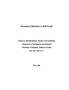
Figure 8 shows 4 different Models of NPP: A VVER FA, a standard PWR FA, a macrocell of a PWR-MOX FA, and a Macro cell of Atucha 2 NPP FA.
Figure 8: NPP FA models: VVER, PWR, PWR-MOX and CNA-II.
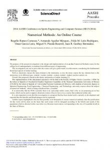
Finally Figure 9 shows a whole core model of the ZR6 research reactor.
Copyright © 2014 Asociación Argentina de Mecánica Computacional http://www.amcaonline.org.ar
3206
E.A. VILLARINO
Figure 9: ZR-6 Whole core model
14 FUTURE WORK CONDOR code is in continuous improvement and currently there are several improvements under development in different levels of progress. Some of this improvements are developed in the framework of the Upgrade of INVAP´s proprietary calculation line developed with the contribution of the Argentine National Agency of Technological and Scientific Promotion (Agencia Nacional de Promoción Científica y Tecnológica -ANPCyT), through the funds of the Argentine Technological Funds (Fondo Tecnológico Argentino, FONTAR):
• • •
• • •
Geometry extension to include 3D modeling capabilities. Including Method of Characteristics (MOC). Improving of the Nuclear Data library, to expand its calculation capabilities with: o (n,2n) and (n,3n) reactions. o More detailed kinetic parameters calculation. o MOC with higher order of anisotropic scattering. o Gamma flux calculation. Thermal-Hydraulic Feedback. Parallelization. Integration through MPI with CITVAP code.
15 CONCLUSION CONDOR code is a flexible tool that can be used in a wide range of reactors. CONDOR was tested in very complex geometries showing good results with low computational effort and resources. For example some users perform 2D whole core calculations for analysis and macroscopic XS calculations. It is used for different institutions, providing a solid behavior of the code under different applications and users. Currently is one of the tools used in the Balseiro Institute in the academic training of the students in the Nuclear Engineering career. It is also used in the Degree, Master and Doctoral thesis of the Balseiro Institute.
Copyright © 2014 Asociación Argentina de Mecánica Computacional http://www.amcaonline.org.ar
Mecánica Computacional Vol XXXIII, págs. 3195-3207 (2014)
3207
REFERENCES Carlvik I. A method for calculating collision probabilities in general cylindrical geometry with applications to flux distributions and dancoff factors, N jnt Conf. on the peaceful uses of atomic energy, geneva 1965 Vol 2, Geneva 1965 p. 225 Ibarra V., Análisis de sensibilidad de secciones eficaces de subgrupos. Trabajo especial para la carrera de ingeniería nuclear. Instituto Balseiro Universidad nacional de Cuyo, 1990. Mochi I., INVAP's Nuclear Calculation System, Science and Technology of Nuclear Installations (Volume 2011, Article ID 215363), 2011. Notari C and Garraffo Z, Spatial self-shielding for heterogeneous cells, Annals of Nuclear Energy 14, 615-618. 1987. Stamm'ler R. and Abbate M. Methods of Steady State Reactor Physics in Nuclear Design, Academic Press, London, 1983. Villarino E. and Stamm'ler R. The Heterogeneous response method in slab geometry, Annals of Nuclear Energy 11, 429 440, 1984. Villarino E., CONDOR: Código de cálculo neutrónico para el cálculo de elementos combustibles con barras, 18th Annual conf. of the Argentinian Association of Nucl. Technology, Buenos Aires, Argentina, 1990a. Villarino, E., Probabilidades de colisión con dependencia angular, 18th Annual conf. of the Argentinian Association of Nucl. Technology, Buenos Aires, Argentina, 1990b. Villarino E., Código de cálculo neutronico CONDOR para la resolución de elementos combustibles nucleares, Tesis Doctoral, Instituto Balseiro, Universidad nacional de Cuyo, 1992 Villarino E., Stamm'ler R., Ferri A. and Casal J., HELIOS: Angularly-dependent collision probabilities, Nuclear Science and Engineering, 112, p 16 31., 1992. Villarino E. and Lecot C., CONDOR v1.3: WWER Lattice Validation, Physor 96: International conference on the physics of reactors, Mito, Japan, 16-20 September 1996. Villarino E and Stamm’ler R., HELIOS: Transformation laws for multiple-collision probabilities with angular dependence. Physor 96: International conference on the physics of reactors, Mito, Japan, 16-20 September 1996 Villarino E., CONDOR Calculation Package, International Conference on the New Frontiers of Nuclear Technology: Reactor Physics, Safety and High-Performance Computing, Physor 2002. Villarino E., Bibliotecas de rutinas de lectura con formato libre FREFMT v3.0, DIN, INVAP SE. 2010. Weiss Z., Optimal algorithm for the calculation of contributions to collision probabilities from a neutron path, Annals of Nuclear Energy 17, 525 530, 1990. Wio H. Transformation law for response fluxes within the collision probability Method, Annals of Nuclear Energy 11, 425 427, 1984.
Copyright © 2014 Asociación Argentina de Mecánica Computacional http://www.amcaonline.org.ar