Numeri~ko modeliranje utjecaja pomo}nog regulatora turbulencije na protjecanje ~elika u me|uloncu. U radu se prikazuju rezultati ra~unalne simulacije ...
T. MERDER, J. PIEPRZYCA
ISSN 0543-5846 METABK 50(4) 223-226 (2011) UDC – UDK 669.186:518.1:531.3=111
NUMERICAL MODELING OF THE INFLUENCE SUBFLUX CONTROLLER OF TURBULENCE ON STEEL FLOW IN THE TUNDISH Received – Prispjelo: 2010-06-21 Accepted – Prihva}eno: 2010-11-05 Original Scientific Paper – Izvorni znanstveni rad
The paper presents the results of computer simulation of steel flow in the two-nozzle tundish of a T-shaped type. The tundish is symmetrical, relative to the transverse plane. The nominal capacity of the tundish is 7,5 Mg of liquid steel. The Fluent program was used to solve the mathematical model of steel casting process. In numerical simulation for modification of steel flow in the tundish subflux controller of turbulence was used. Three variants of subflux controller of turbulence configurations in the tundish were tested. As effect of mathematical calculations liquid steel velocity, turbulence intensity, turbulent kinetic energy and characteristic of Residence Time Distribution (RTD) have been obtained. Key words: steel, tundish, numerical modeling, mixing time, subflux controller of turbulence Numeri~ko modeliranje utjecaja pomo}nog regulatora turbulencije na protjecanje ~elika u me|uloncu. U radu se prikazuju rezultati ra~unalne simulacije protjecanja ~elika u me|uloncu s dva otvora u obliku slova T. Me|ulonac je simetri~an s obzirom na transverzalnu ravninu. Nominalni kapacitet me|ulonca je 7,5 Mg teku}eg ~elika. U numeri~kog simulaciji za modificiranje protjecanja ~elika u me|uloncu kori{ten je pomo}ni regulator turbulencije. Testirane su tri varijante pomo}nog regulatora turbulencije u me|uloncu. Kao rezultat matemati~kog prora~una dobiveni su brzina teku}eg ~elika, intenzitet turbulencije, kineti~ka energija turbulencije i karakteristika raspodjele vremena zadr`avanja (RVZ). Klju~ne rije~i: ~elik, me|ulonac, numeri~ko modeliranje, vrijeme mije{anja, pomo}ni regulator turbulencije
INTRODUCTION In recent years, numerical simulations have become an integral part of research on the optimization of the continuous steel casting technology. The dynamic development of computational codes and constantly increasing processing power of computers have provided an excellent work tool. Due to that fact, mathematical modelling enables the understanding of metallurgical processes to the extent of something that was not possible previously. High temperatures prevailing in metallurgical equipment restrict research conducted on real facilities. Numerical studies concerning the hydrodynamics of steel flow in tundishes are being successfully carried out at present. These are targeted at the optimization of the working space of facilities. This is associated with additional furnishing the tundish with flow control devices (dams, subflux controllers of turbulence). However, interfering in the working space of the tundish will result in a change in the operation conditions of the entire continuous casting machine (CCM). Therefore, any proposed modifications of tundish furnishing must be supported by studies. Both physical and numerical modT. Merder, J. Pieprzyca, Silesian University of Technology, Department of Metallurgy, Katowice, Poland
METALURGIJA 50 (2011) 4, 223-226
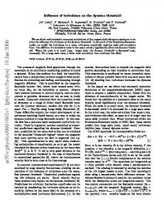
elling are used for this purpose [1-4]. A commonly used variant of tundish working space furnishing involves equipping the tundish with a subflux controller of turbulence. The subflux controller of turbulence helps to control the steel flow in the tundish in order to improve the casting process. The subflux controller of turbulence device is placed in the tundish below the teaming stream of the ladle and creates a flow pattern that supports inclusion flotation and “plug flow” and thus helps the steelplant to produce a clean steel. Figure 1 shows the directions of steel flow in the tundish with impact pad and subflux controller of turbulence installed.
Figure 1 Inlet stream of the steel flow in the tundish with impact pad and subflux controller of turbulence 223
T. MERDER et al.: NUMERICAL MODELING OF THE INFLUENCE SUBFLUX CONTROLLER OF TURBULENCE...
The subflux controller of turbulence is a device that embodies several constructional solutions. Therefore, it’s geometrical parameters must be adjusted to the specific tundish geometry. The paper present the results of numerical simulation of steel flow in a two-nozzle tundish. For the modification of steel flow in the tundish under investigation, subflux controllers of turbulence were used. Three geometrical variants of the subflux controller of turbulence were considered. Results of the testing of changes in the characteristics of steel flow in the variants considered are presented. Numerical computation under transient conditions enabled RTD curves to be plotted. The obtained results have enabled the selection of the optimal geometrical variant of the subflux controller of turbulence for the facility under study.
TUNDISH DESCRIPTION The object of the study is a “T”-type tundish designed for the continuous casting of slabs intended for small cross-section rolled products. The tundish is symmetrical relative to the lateral plane. The nominal capacity of the tundish is 7,5 Mg of liquid steel. The geometric dimensions and configuration of the industrial tundish are shown in Figure 2. The effects of subflux controller of turbulence on flow characteristics in the tundish with different configurations were investigated. Three different flow control arrangements were studied. Different tundish configurations studied in present work are shown in Figure 3.
MATHEMATICAL MODEL Fundamental equations A typical three dimensional fluid flow model is based on the continuity equation and Reynolds-averaged Navier-Stokes equations for incompressible Newtonian fluids, conserving mass momentum and energy at every point in a computational domain. Additionally an equation
Figure 3 Different tundish configurations studied in present work
describing the turbulence of liquid steel motion in the tundish is used. For the modelling of turbulence, the semi-empirical two-equation k-e model proposed by Launder and Spalding [5] was employed, which is commonly used in the analysis of engineering problems. This model, in many cases of turbulent flows, gives result close to those of an experiment, with limited computational outlays. The equations are described in detail in papers [6,7].
Residence time distribution model Residence Time Distribution (RTD) is a statistical representation of time spent by an arbitrary volume of the fluid in the tundish. It is obtained by creating a change at the inlet and measuring of the system response at the outlet with time. When the dimensionless concentration at the outlet is registered against dimensionless time, it creates the RTD curve. For generating the curve, scalar or species transport model is used. It solves the following equation for the time evolution of the species mass fraction C, giving the steady flow velocities calculated previously from the turbulence model. ¶( r cC ) ¶( r c ui C ) ¶æ ¶C ö ÷ (1) + = ç ç r c Deff ÷ ¶t ¶x i ¶x i è rx i ø where the effective diffusion coefficient (Deff) is the sum of the molecular diffusion coefficient and the turbulent diffusion coefficient (2) Deff = Dm + Dt The turbulent diffusion coefficient is determined from the following relationship (assuming that the turbulent Schmidt number is equal to unity).
Initial and boundary conditions
Figure 2 Geometry dimensions of industrial tundish, [mm] 224
Half of the tundish was chosen for the mathematical analysis. The computational space discretization has been made with use of the computational mesh consisting of 250000 control volumes. Figure 4 shows the computational mesh employed in these simulations. In the object under study, a hybrid computational grid ware generated in the GAMBIT program [8]. Appropriate boundary conditions were chosen for the system of differential equations. As the considered spatial system is symmetrical relative to the plane passing through the pouring gate axis, this resulted in the zeroing of the first derivatives in relation to the direction norMETALURGIJA 50 (2011) 4, 223-226
T. MERDER et al.: NUMERICAL MODELING OF THE INFLUENCE SUBFLUX CONTROLLER OF TURBULENCE...
Table 1
Parameters and boundary conditions used in modeling
Parameter
Figure 4 Three-dimensional view of the unstructured mesh and boundary conditions for simulations
mal to the plane of symmetry. The boundary conditions for momentum transfer were those of non-slipping at the solid surfaces, zero normal velocity gradients at the symmetry planes, and the free surface of the liquid. The standard wall function is used to calculate the value of a node near a solid wall. The other parameters and boundary conditions of the tundish are listed in Table 1. In order to develop concentration characteristics (RTD) corresponding to normalized conditions, the boundary condition was applied at the pouring gate in the form of a stepwise change of concentration (C = 1).
Value
Depth of molten steel / mm
600
Shroud diameter / mm
50
Inlet turbulence intensity / %
5
Casting speed / m·min-1
1
Operating temperature / K
1 828
Density of molten steel / (kg·m-3)
7 000
Viscosity of molten steel / (kg·m-1·s-1)
0,007
Specific heat / (J·kg-1·K-1)
830 -1
-1
Thermal conductivity / (W·d ·K ) -2
40,5
Heat flux at free surface / (kW·m )
15
Heat loss from wall / (kW·m-2)
3,8
Heat loss from internal wall / (kW·m-2)
1,75
Mathematical method The fluid flow and heat transfer model was solved using standard k-e turbulece model with second-order upwind discretization scheme [9]. The model formulation utilized segregated study state solver with implication formulation. Discretization equations were derived from the governing equations and were solved by using an implicit finite difference procedure called SIMPLEC [10] algorithm. The solution was started with the default under-relaxation variables, which were later reduced to achieve the converged solution. Convergence criteria of 1·10-6 were fixed for all the equations. Velocity fields at steady state were first calculated and later they were employed to solve the mass transfer equation. For the species transport model, the solution was considered converged when the residual for mass fraction was below 1·10-5. Time step of 0,5 s with approximately 20 iterations in each time step was utilized to generate the RTD curve. Calculation was performed by using the commercial program FLUENT [9].
RESULTS AND DISCUSSION The turbulence kinetic energy field of liquid steel at the symmetric plane in the impact zone of the incoming stream from the ladle shroud in the tundish is shown in Figure 5. From figure 5A in can be seen, that the liquid steel from the shroud impacts the tundish bottom directly with very high velocity (turbulence intensity). Then it flows fast along the bottom. Such flow can cause serious erosion of the tundish bottom and side walls in this zone and arise large exogenous inclusions. METALURGIJA 50 (2011) 4, 223-226
Figure 5 Isolines of steel turbulence kinetic energy a) configuration A, b) configuration B, c) configuration C, d) configuration D
Figures 5B, 5C and 5D show that the turbulence energy of the incoming stream is depressed with the turbulence inhibitor. It is shown in figures 5B and 5C that the surface turbulence kinetic energy is high and eddies exist near the shroud, which will result in slag entrapment. The turbulence kinetic energy fields and the distribution of velocity vectors provide a significant knowledge of steel casting conditions, however, these characteristics do not directly explain of whether the tundish condition is suitable for nonmetallic inclusion removal or agi225
T. MERDER et al.: NUMERICAL MODELING OF THE INFLUENCE SUBFLUX CONTROLLER OF TURBULENCE...
tation processes in the sequential casting of different steel grades, or not. The answer to this question is provided by RTD curves. Quantitatively one can assess the intermediate area through determination of it’s range (Dt) determined on the base of difference in times necessary for obtaining concentrations at the levels of 20 and 80 % of the concentration anticipated for the given steel grade. The characteristic mentioned is commonly used to assess and compare the working areas of different tundishes [11] and casting conditions. Assuming that value of 0 on the ordinate axis of the presented curve corresponds to the current sort of the steel cast, while the value of 1 corresponds to the subsequent one, we can determine the dimension of the area range (in other words, the range of 0,2÷0,8 of the dimensionless concentration). The Dt values for separate curves, obtained as a result of the investigations, are shown in Table 2. Figure 6 shows the comparison of four studied cases. In order to allow the direct comparison the results, the marker concentration is presented in the dimensionless form. It can be seen from Figure 6, that the behaviour of the curves is practically identical, but the obtained times of the transient zone range differ from each other considerably. The presented computations show clearly that the smallest value of the transition zone has been obtained for Configuration C, use and is equal to 255,5 seconds (Table 2). This indicates the appropriateness of selection of the tundish working space furnishing variant as against the unfurnished tundish (Configuration A). In the case of Configuration D, the longest time of the transient zone range occurs. Table 2 The results of transient zone Tundish
Transient zone /s
Configuration A
313,5
Configuration B
276,5
Configuration C
255,5
Configuration D
319
CONCLUSION For developing the characteristics of the flow in the steel continuous casting tundish and evaluating the effect of the modification of the internal tundish geometry on basic casting parameters, a numerical modelling technique was used. The simulation results made it possible to obtain detailed distributions of velocity, temperature and turbulence kinetic energy fields, as well as the characteristics of the distribution of tracer concentration in the steel. Observations collected during the investigations can be summarized in a following manner: – In the bare tundish, the liquid steel flow velocities in the impact zone of the incoming stream are high and eddies form easily on the free surface around the long shroud. – Subflux controller of turbulence can effectively control and improve the fluid flow in the impact 226
Figure 6 RTD curves for the different configurations studied
zone of the tundish. Such improvement in molten flow characteristic in the tundish would be benefited to the flotation for the non-metallic inclusions and the decrease in the exogenous inclusions. – The installation of the subflux controller of turbulence in the tundish has resulted in a reduction of the transient zone range in two cases. The most advantageous casting conditions are met for Configuration C - the transient zone range is the shortest one. – The use of an inappropriate geometry of the subflux controller of turbulence in the tundish will result in a worsening of the hydrodynamic conditions of steel flowing through the tundish (Configuration D). The tundish upgrading process has not to be ended at this stage, as further modifications are still possible, such as installing additional dams.
REFERENCES [1]
S. M. Lee, Y. S. Koo, T. Kang, I. R. Lee, Y. K. Shin, Sixth International Iron and Steel Congress ISIJ, (1990) 3, 239-245 [2] R. K. Singh, A. Paul, A. K. Ray, Scand. J. Metall., 32 (2003), 137 [3] A. Robert, D. Mazumdar, Steel Research, 71 (2001), 97-102 [4] T. Merder, J. Pieprzyca, Z. Kudliñski, L. Bulkowski, U. Galisz, H. Kania, Wiadomoœci Hutnicze, (2009) 3, 178-184. [5] B. E. Launder, D.B. Spalding, Methods in Applied Mechanics and Engineering, 3 (1974), 269-289. [6] J. F. Wendt, Computational fluid dynamics, Springer-Verlag, Germany, 1996. [7] T. Merder, J. Jowsa, M. Warzecha, Brno, Czech Republic, (2005), 593-560. [8] Gambit User’s Guide, Fluent Inc., 2005. [9] FLUENT User’s Guide, Fluent Inc., 2007. [10] SV. Pathankar, Numerical heat transfer and fluid flow, Hemisphere Publishing Corporation, NY, 1980. [11] M. Clark, T. Wagner, A. Trousset, IOM Annual Ceramics Convention, (2002), 14-19. Note: The responsible translator for English language is P. Nowak, Katowice, Poland.
METALURGIJA 50 (2011) 4, 223-226