Ãtudes des méthodes d'entreposage des roches stériles pour prévenir la génération d'eaux de drainage minier acides, MSc thesis (unpublished, in French), ...
HOME Numerical Modelling of Unsaturated Flow in Uniform and Heterogeneous Waste Rock Piles O Fala1, M Aubertin1,3, J Molson1, B Bussière2,3, G W Wilson4, R Chapuis1 and V Martin1 ABSTRACT Waste rock piles containing reactive sulfide minerals can serve as long-term sources of acid mine drainage (AMD). Within these piles, many physical, geochemical and biological processes can contribute to the production of AMD. The flow of water, for example, depends on internal pile structure, which depends on the dumping methods used to construct the pile. In this paper, the internal structure and grain size distribution of typical waste rock piles are first reviewed with respect to their effect on internal water flow. A numerical model is then applied to simulate unsaturated flow within a waste pile assuming two primary waste materials, different atmospheric conditions and several geometric configurations. The simulations suggest that water movement can be controlled by introducing fine-grained material layers within the coarser host material. However, these layers should not be horizontal because they can lead to localised high-saturation regions as well as preferential flow favouring the production of AMD. A shallow slope towards the pile boundary may be introduced to force drainage to the outside while maintaining low saturation within the interior, thus reducing the production of AMD.
This paper presents numerical simulations of unsaturated flow within rock waste from hard rock mines. Additional processes affecting AMD, including the transport of air (convective, advective or diffusive) and heat, are subjects of complementary studies and are not included here; for further information on these issues, the reader is referred to Lefebvre et al (2001a, b), Mbonimpa et al (2002) and Aachib, Aubertin and Mbonimpa (2002). Geotechnical issues are reviewed by Aubertin, Bussière and Bernier (2002).
CONSTRUCTION METHODS AND INTERNAL STRUCTURE
1.
École Polytechnique, Montreal, Department of Civil, Geological and Mining Engineering, PO Box 6079 Sta. Centre-Ville, Montreal QC H3C 3A7, Canada.
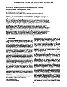
Figure 1 illustrates a schematic cross-section through a waste rock pile, constructed over a relatively flat surface, showing the internal stratigraphy that can develop from different construction methods. This conceptual model is used as a basis for the numerical simulations shown below. In the conceptual model of Figure 1, horizontal layers of variable density develop from the operation of heavy equipment. The layering may also be enhanced in some cases by material degradation when coarse particles near the surface are broken down mechanically or by atmospheric weathering. The thickness and spacing between such denser and/or finer grained material layers depends on the construction sequence, nature of the rock waste, and type of equipment being used. The texture of these layers tends to enhance water retention, relative to the unaltered waste rock, which in turn influences the degree of saturation and flow of water within the pile. This type of internal structure has been observed in many waste rock piles (Smith et al, 1995; Newman et al, 1997; Wilson, Wilson and Fredlund, 2000). To further characterise these systems, the authors are presently conducting in situ investigations using geophysical methods, infiltration tests, excavation, and sampling. Close to the external boundaries of the dump, the effect of particle segregation is more visible, as this area is less affected by heavy equipment traffic. In these areas of a pile, there is a marked heterogeneous distribution of waste rock, with inclined but somewhat discontinuous layers of fine-grained and coarsegrained materials (Wilson, Wilson and Fredlund, 2000). At the bottom, there is often a significant accumulation of cobbles and large size particles, making this an almost open zone for air and water flow (at least close to the edge of the pile). Hence, along the slope, the sequence of deposition induces alternate sheets of waste, as coarse and fine material layers are added progressively during dump construction. The internal structure that develops during construction plays an important role in the movement of water and air in waste rock dumps. In the following section, various modes of material deposition and pile construction are presented.
2.
UQAT-URSTM, Department of Applied Sciences, 445 boul. de l’Université, Rouyn - Noranda QC J9X 5E4, Canada.
Deposition
3.
Industrial Chair CRSNG Polytechnique-UQAT, Environment and Mine Waste Management.
4.
Chair, Mining and the Environment, Department of Mining Engineering, University of British Columbia, 2329 West Mall, Vancouver BC V6T 1Z4, Canada.
INTRODUCTION Waste rock piles are surface deposits of rock waste from mine operations. The piles can be enormous, extending more than 300 m in height and containing more than 500 million m3 of waste (McCarter, 1990). Rock wastes are sometimes used as backfill for underground mines, however in most cases they are disposed at ground surface. Waste rock piles are characterised by relatively coarse-grained material covering large areas, and are exposed to variable climatic conditions. As with the accumulation of tailings, mine water and treatment sludge, rock waste must be carefully managed to minimise environmental impacts. During and after construction, a rock pile can become a type of natural reactor; its boundaries are open to water and air flow, and if it contains reactive sulfide minerals, a series of complex natural processes can develop, which leads to the production of acid mine drainage (AMD) (eg Ritchie, 1994; Lefebvre et al, 2001a). The primary chemical process responsible for AMD in reactive rock piles is the oxidation of sulfide minerals (eg pyrite) in contact with water. The rate of pyrite oxidation is strongly dependent on the degree of water saturation because oxygen has a low solubility and diffusivity in water. The prediction and control of acid generation therefore requires a sound understanding of the distribution and movement of water within the rock piles. It is not, however, a simple task to predict the hydraulic conditions which develop within a waste rock pile (eg Noël and Ritchie, 1999).
6th ICARD
Four principal methods of deposition for waste rock piles can be identified. The choice of method for a particular site depends on local topography, the type and dimensions of the equipment used for handling and transporting the rock waste, as well as on the physico-chemical properties of the waste. Each method produces
Cairns, QLD, 12 - 18 July 2003
895
O FALA et al
FIG 1 - Conceptual cross-section of a waste rock pile showing internal structure.
a different degree of compaction and grain size distribution that can have significant effects on the movement of water and gases within waste rock piles (Morin et al, 1991; Fala, 2002). In method I, called end-dumping, the waste rock is deposited directly using dump trucks across the crest of the pile. With method II, known as push-dumping, the waste rock is dumped near the crest using trucks or conveyors, then pushed over the crest with bulldozers. Method III involves free dumping, in the form of individual stacks (heaps) of approximately 2 m height, whose surface is then leveled and compacted. Finally, method IV uses a dragline or bucket excavator for transport and handling of the waste. This method is common in large-scale open pit coal mining. In method I, three zones of different grain size can often be distinguished: an upper zone consisting of fine particles, a lower zone consisting of coarse material and a transition zone of intermediate, non-uniform grain size material. The height of the slope does not seem to influence this distribution, although in general, material segregation is less noticeable for lower dump heights (Morin et al, 1991). In method II, coarse material is found at the base of the slope, but there is less segregation at the top of the dump. For example, in method II, 40 per cent of the coarse material reaches the foot of the slope (compared to approximately 75 per cent for method I), because of lower initial angular velocities of the coarse material when it is pushed rather than dumped over the crest (Morin et al, 1991). In method III, segregation is less pronounced, and the material remains denser than in the first two methods. Method III is often used to initiate the construction of a rock pile, and is later replaced by method I or II when the pile is high enough. When a dragline or bucket excavator is used, (method IV), segregation is further reduced since the grain size distribution tends to be more uniform. In some cases, weak segregation can occur if the grain size distribution is non-uniform (Morin et al, 1991). Rock waste can also be deposited concurrently with tailings (or other fine-grained material), by mixing, alternating layers, or construction of confined cells. This technique, sometimes called co-deposition, has often been used in order to control additional problems, besides acid mine drainage, including the stability of retention dams, and restoration of stacks containing contaminated material (eg see Aubertin, Bussière, and Bernier
896
2002; Wilson et al, 2003). These approaches are not considered directly here; the interested reader will find some recent applications in the literature.
Grain size distribution The grain size distribution of the waste rock and the method of construction of the dumps play controlling roles in the movement of fluids (water and gas) inside a pile. In the case of waste from hard rock mines, a typical grain size curve shows a well-graded distribution with a coefficient of uniformity CU (= D60/D10) of 20 or higher (Morin et al, 1991; McKeowen et al, 2000; Fala, 2002). Waste rock particles become segregated according to their size during construction of a rock pile. The degree of segregation depends on the method of construction. In the case of methods I and II for example, a layer of fine material is typically found on the surface of the dump and a layer of coarser material is found at the base. This layering is particularly noticeable when the grain size distribution is open and constrained within a narrow range. As the dump grows bigger, the bulk grain size distribution then includes alternating fine and coarse-grained material layers (Morin et al, 1991; Fala 2002). On the other hand, when the grain size distribution is broad, reflecting a large variability of the waste rock, the vertical pile profile can be irregular and the structure of alternating fine and coarse layers is less distinct (Fala, 2002).
WATER FLOW WITHIN ROCK PILES The flow of water has a significant effect on the physical and chemical behaviour of a rock dump. The various hydraulic parameters controlling this water flow depend to a large extent on the grain size distribution of the waste material (Yazdani, Barbour and Wilson, 2000). The shape of the water retention curve, for example, varies with the grain size distribution as well as the degree of compaction; the retention tends to increase when the particle size and porosity decrease (Aubertin, Bussière and Bernier, 2002). Also, the saturated hydraulic conductivity (ks) generally increases with the average size of the particles. The grain size effect can, however, be counterbalanced by a drop in porosity, which may occur when the proportion of coarse particles increases.
Cairns, QLD, 12 - 18 July 2003
6th ICARD
NUMERICAL MODELLING OF UNSATURATED FLOW IN UNIFORM AND HETEROGENEOUS WASTE ROCK PILES
The parameters included in these equations and the corresponding values used for the current simulations are presented in Table 1 and the corresponding curves are shown in Figure 2. These two materials have a rather low water retention capacity since they correspond to coarse-grained materials with a relatively uniform grain size distribution.
The hydraulic conductivity depends on the water content, and influences the capacity of the dump to transmit water to the surrounding medium. Morin et al (1991) report that the saturated hydraulic conductivity can vary from 100 cm/s (porosity from 35 to 40 per cent) for piles composed of volcanic and metamorphic (coarse-grained) rocks, to 10-7 cm/s for argillaceous (finegrained) piles. Martin (in preparation) presents some specific data on the values of ks and on water retention parameters measured in laboratory and field tests. As the water content approaches the residual water content, the effective hydraulic conductivity approaches zero. The hydraulic properties of waste rock vary within most dumps. Stratification within the pile, for example, tends to create alternating layers of less permeable zones (denser or finer material) with a higher moisture content. This stratification can be correlated to the activity of mining machinery (small-scale) or to material segregation which occurs during deposition (largescale). Zones of highly porous material can also be formed in heterogeneous dumps, which can create local flow systems or channeling. These zones of preferential flow can be caused by vertical, horizontal or inclined layers of high hydraulic conductivity, and often control the movement of water in dumps. Smith et al (1995), Zhan (2000) and Li (2000) and others confirmed the existence of such preferential flowpaths in laboratory (waste rock models) and field scale (waste pile) situations. Work is currently underway by the authors to develop improved methods of characterising and modelling these phenomena.
0.3
-10
k( θe ) = k s θel [1 − (1 − θe
1
mv
is the effective water saturation
θ
is the (volumetric) water content
θs
is the saturated water content
θr
the residual water content
ψ
the suction pressure
-10
is the saturated hydraulic conductivity
l
is a parameter representing the degree of pore connection
0
-8
-6
-4
-2
0
k (m/s)
10 10-6 -8 10 10-10 -12 10 -14 10 10-16 -18 10
All simulations were completed using the HYDRUS2D (version 2.0) finite element flow model (Simunek, Sejna and van Genuchten, 1999). The model simulates single-phase, isothermal fluid flow and neglects porosity changes due to mineral precipitation or dissolution. Waste pile consolidation is not considered. To improve mass balance for large scales, the principle of similitude was applied, which uses dimensionless variables to facilitate system scaling (Fala et al, 2001; Fala 2002). This approach helped ensure convergence which can be difficult in some numerical approaches due to the highly non-linear water retention characteristics (Wilson, Wilson and Fredlund, 2000). The conceptual models for the numerical simulations represent axisymmetric and two-dimensional sections of a waste pile. In the axisymmetric systems, the waste pile is assumed radially symmetric about the vertical centreline (left boundary), while the 2D case assumes a relatively long transverse width relative to the length. Across the upper boundary and end-slope, a seasonallyvarying recharge is assigned, while the left boundary is assumed to be a symmetrical flow divide (impermeable). The surface recharge boundary conditions are provided in Table 2 based on observed average daily precipitation and evapo-transpiration from Latulipe in northern Quebec during the last 20 years (Figure 3). As an initial condition, the water table was fixed at -5 m relative to the base of the rock pile and the pore pressure was assumed at equilibrium from the base to the top of the pile. At 0 m elevation, a free drainage condition was adopted for all simulations. This is meant to reproduce the effect of a coarse, well-drained layer that is often found at the base of a waste rock pile.
α v, mv, nv are the van Genuchten (1980) parameters ks
0
FIG 2 - Water content and hydraulic conductivity curves used in the model for the sand (SBL) and gravel (GRV) materials (see Table 1 for van Genuchten parameters).
(2)
is the saturation-dependent hydraulic conductivity
-2
suction pressure (kPa)
(1)
k( θe )
-4
GRV
where: θe
-6
-4
mv
)m v ]2
-8
SBL
Two types of rock waste units are included in the present modelling study: a sandy material (SBL) and a gravel material (GRV). Bussière (1999) studied the hydraulic properties of these materials and determined the parameters for the van Genuchten (1980) model given by: θ − θr 1 = θ s − θr 1 + ( α v ψ )n v
0.1
GRV (gravel)
NUMERICAL SIMULATIONS
θe =
0.2
SBL (sand)
water content (θ)
0.4
TABLE 1 Values of the van Genuchten (1980) parameters used in the current study (see Figure 2). θr
θs
α v(m)
l
nv
ks (m/s)
GRV
0
0.39
14 960
0.5
1.45
4.7 × 10⁻³
SBL
0.01
0.29
3
0.5
3.72
5.1 × 10⁻⁵
6th ICARD
Cairns, QLD, 12 - 18 July 2003
897
O FALA et al
evapo-transpiration
0.4
Rate (cm/day)
Figures 4 to 8 show the simulated water content distributions after one and/or three years for all simulations. The geometric configuration of the piles is also shown with each simulation. Table 3 provides dimensions and a summary of the simulation characteristics (S1 to S5). Convergence and mass balance was verified for all simulations (Fala, 2002). Simulation S1 (Figure 4) shows that in a homogeneous pile made of gravel material (GRV, initially dry), water infiltrates into the pile to a uniform depth and forms a wetting front with a relatively high moisture content relative to the rest of the pile. After one year, the partially saturated wetting front reaches a depth of about 5 m. The rate of advancement of the front is a function of the precipitation and evapo-transpiration rate, and of the moisture content of the material near the surface of the pile. In this case, the evapo-transpiration rate is greater than the precipitation rate for three months: June, July and August, the three warmest months of the year. During this period, water is extracted upwards towards the surface because of the high water
0.3 precipitation
0.2 0.1 0
0
30
60
90 120 150 180 210 240 270 300 330 360
Time (days)
FIG 3 - Observed precipitation and evapo-transpiration from Latulipe, Quebec, as used in the numerical model (data provided in Table 2).
FIG 4 - Simulation S1, homogeneous gravel (GRV); conceptual model (left) and water content contours after one year (right).
TABLE 2 Observed climatic conditions (precipitation and evapo-transpiration) used in the numerical model (see Figure 3).
Precipitation (cm/d) Evapo-transpiration (cm/d)
Jan
Feb
Mar
April
May
June
July
Aug
Sept
Oct
Nov
Dec
0.182
0.15
0.191
0.22
0.258
0.307
0.302
0.314
0.324
0.293
0.231
0.230
0
0
0
0.046
0.237
0.339
0.407
0.345
0.21
0.089
0
0
TABLE 3 Characteristics of simulations S1 to S5. Geometric configuration Internal dimensions Ht (m)
Hp (m)
Hmin (m)
Hmax (m)
Lb (m)
Lb1 (m)
Lb2 (m)
Dim. Ls (m)
Ep (m)
I2 (%)
MAT.6
Period
1 year
4
Slope3
S11
20
45
5
2H/1V
Axisym.5
GRV
S2
20
45
5
2H/1V
Axisym.
SBL
1 year
S3
20
2H/1V
Axisym.
SBL GRV
3 years
S4
20
2H/1V
2D
SBL GRV
1 year
S5
20
2H/1V
Axisym.
SBL GRV
3 years
10 4
5
10
Notes: 1. Simulation S1 2. Inclination of the fine-grained layers 3. Surface slope, horizontal (H): vertical (V)
898
50
25
5
1
40
20
20
1.5
50
25
5
1
5
4. Dimensionality 5. Axisymmetric 6. Material identification (see Table 1)
Cairns, QLD, 12 - 18 July 2003
6th ICARD
NUMERICAL MODELLING OF UNSATURATED FLOW IN UNIFORM AND HETEROGENEOUS WASTE ROCK PILES
FIG 5 - Simulation S2, homogeneous sand (SBL); water content after one year.
suction and a local water content of nearly zero. The precipitation rate is higher than the evapo-transpiration rate for the remainder of the year, and the water content increases above the residual water content for the GRV gravel. By the end of the year, the maximum water content, near the surface, reaches approximately 0.1 (Sr = 25 per cent for n = 0.39). In simulation S2 (Figure 5), in which the GRV material is replaced by SBL, the depth of the wetting front after one year increases to about 16.5 m. However, the maximum water content is much lower than within the GRV, on the order of 0.03 (Sr = 10 per cent, n = 0.29) at the front. In relation to the GRV, the wetting front is displaced more rapidly and there is less local water accumulation. The simulations therefore show that the water content and depth of the wetting front (after one year) depend significantly on the material characteristics, and also on the initial and boundary conditions. They depend much less on the geometric configuration when considering a single homogeneous material (as demonstrated by other simulations – not shown here; Fala, 2002).
FIG 6 - Simulation S3, horizontal layers of SBL within GRV host; conceptual model (top left) and corresponding water content after one year (left) and three years (right).
FIG 7 - Simulation S4, heterogeneous zones of SBL within GRV host; conceptual model (left) and water content after one year (right).
6th ICARD
Cairns, QLD, 12 - 18 July 2003
899
O FALA et al
FIG 8 - Simulation S5, inclined layers of SBL within GRV host; conceptual model (top left), and corresponding water content after one year (left), and three years (right).
Simulation S3 represents the case in which two layers of SBL material (each approximately 1 m thick) are placed within the bulk GRV host material. Figure 6 shows that in this case, the GRV material near the boundary slope behaves as if the SBL layers did not exist. The wetting front penetration depth and the maximum water saturation, for example, are the same as in simulation S1. At the same time, more water tends to accumulate and flow within the SBL layer than within the GRV which surrounds it. This is a result of the capillary barrier effect that inhibits water from entering the coarser adjacent material. Once the pressure in the SBL exceeds the water entry pressure of the GRV, water begins to infiltrate the latter. Within the SBL, the water content becomes relatively high, between 0.2 to 0.28 (Sr = 69 to 97 per cent) near the interface with the GRV. This quasi-saturated section within the SBL layer has a thickness of about 20 cm. It was observed that after the second month, the SBL material was already transporting water to the GRV below. The infiltration occurred at quasi-random ‘percolation points’ which appear along the SBL layer due to geometric irregularities at the SBL/GRV interface, and due to hydraulic characteristics of the two materials (Fala, 2002). Simulation S4 (Figure 7) shows the case of unsaturated flow within a strongly heterogeneous (but idealised) system. Here, water flow depends on the distribution of fine material layers within the pile. Compared to a homogeneous pile or a pile with horizontal layers, water infiltrates more quickly and deeply within the heterogeneous pile, assuming the same boundary and initial conditions. Heterogeneous and/or stratified conditions also seem to favour the development of preferential flow. Simulations S3 and S4 represent situations that can augment the production and migration of AMD. Although in these cases water exists almost everywhere within the dump, the saturation is rather low which in turn allows free air circulation and therefore may induce potentially high oxidation rates. With case S3 in
900
particular, in which the dump contains horizontal layers of relatively fine material (SBL) within a coarser material (GRV), the fine material does not prevent water from infiltrating to the bottom and towards the centre of these dumps. In certain cases, the layers of SBL even contribute to a form of ponding within the dump (if one compares it to the case with material GRV alone, see S1 versus S3). This is due to the fact that the fine material layers retain more water than the coarse material around them. Once the water pressure in these layers exceeds the water entry pressure of the GRV, water seeps into this material and advances through the dump. The accumulation of water with relatively low saturation allows oxygen to infiltrate the pile and augment the rate of AMD production. To help counter this phenomenon, the installation of SBL layers with a slope towards the outside of the dump could be beneficial. These sand layers become lateral 2D capillary barriers which divert water towards the outside of the dump, as shown in simulation S5 (Figure 8); in this case, the layers of SBL are inclined at an angle of five per cent. In simulation S5, the percolation points at the SBL-GRV interface have disappeared and the water that accumulates in the SBL layers is directed towards the outside of the dump. This geometric configuration of the fine material layers has two advantages: it prevents deep infiltration and it directs accumulation of water toward the edge of the dump. Consequently, during the entire simulation period, the water content in the centre of the dump remains unchanged. Towards the outside of the dump, the water content increases, thus reducing the potential for air to infiltrate the dump (compared to the case of a dump with horizontal layers of SBL). Although the water content near the pile face is somewhat higher in this scenario, erosion rates and slope stability are not likely to be significantly affected because the system remains unsaturated and flow rates within the inclined structures would remain low relative to surface run-off.
Cairns, QLD, 12 - 18 July 2003
6th ICARD
NUMERICAL MODELLING OF UNSATURATED FLOW IN UNIFORM AND HETEROGENEOUS WASTE ROCK PILES
Within the uppermost SBL layer, water is transmitted to the edge of the dump rather than towards the interior. The flow system is well-behaved with local regions of high saturation clearly identified. Discharge is thus reduced near the base of the dump to a peripheral ring which decreases in width when the pile slope is increased. The discharge zone can therefore be related to the circumference of the dump. Long-term control of AMD could be achieved if this outer zone is constructed using low or non-reactive waste rock material.
CONCLUSIONS AND ONGOING RESEARCH The numerical simulations presented herein suggest that it may be possible to control the flow of water within waste rock piles when the waste materials are deposited with graded bedding, inclined towards the outer pile boundary, and with a fine-grained layer placed above a coarse-grained layer. These layers form a capillary barrier, preventing the percolation of water towards the centre of the pile and diverting water toward the exterior. As a result, a large proportion of the rock pile remains dry. In the simulated inclined system, water flows to the flanks of the pile within the fine-grained layered material. A zone of higher saturation therefore develops at the pile boundary as the pile is extended outward, leaving former boundary zones buried within the dryer interior. The precise configuration that maximises these effects, including layer spacing, inclination and thickness, depends on the properties of each material, the pile geometry, and the components of the hydraulic fluid balance. Because flow rates within the pile remain relatively low under natural recharge conditions, slope stability in these scenarios should not be adversely affected. Several additional studies are continuing within the authors’ groups (NSERC Industrial Chair of École Polytechnique-UQAT, and UBC Chair on Mining and the Environment). They include the optimisation of conceptual models for the systems presented here, as well as investigations of preferential flow and dumping practices that can affect the grain size distribution within rock piles. Improved measurement and monitoring tools are also being developed to better characterise the internal structure of existing piles, including geophysical methods and infiltration tests. Alternative disposal methods, such as a combined placement of waste rocks and tailings (or paste fill), are also being studied. The flow of water, transport of aqueous components and dissolution/precipitation of solid minerals are closely coupled processes in mine tailings and rock piles, and they interact in complex ways to generate AMD (or ARD). Numerical models are often the best way to study these interactions, to evaluate parameter sensitivity and to compare closure or remediation scenarios. Model development is in progress to evaluate the interaction between flow and transport through tailings and rock waste. Using coupled flow and reactive mass transport models (see, for example, Gerke, Molson and Frind, 1998; Bain et al, 2001; Meyer, Frind and Blowes, 2002), the evolution of AMD (containing acidity, high Fe, SO4 and metals) will be simulated for different systems, including the pile structures considered here. Net acidic discharge can be compared for different material compositions and structures, and the influence of remediation or closure options on AMD can be determined. New conceptual models for the physical structure of rock and waste piles will also be incorporated into the numerical models, for example using some recent characterisation work from Barbour and Hendry, (2002). A recently-developed conceptual model for oxygen diffusion (Mbonimpa et al, 2002; Aachib, Aubertin and Mbonimpa, 2002) will be introduced to determine the influence on AMD generation, and transient flow processes, including partial flooding will also be considered.
6th ICARD
ACKNOWLEDGEMENTS The core of this research was financially supported by the Natural Sciences and Engineering Research Council of Canada (NSERC) and by the partners of the Polytechnique-UQAT Industrial Chair in Environment and Mine Wastes (www.polymtl.ca/enviro-geremi). The authors would like to thank Lucette de Gagné for help in preparing the manuscript.
REFERENCES Aachib M, Aubertin, M and Mbonimpa, M, 2002. Laboratory measurements and predictive equations for gas diffusion coefficients of unsaturated soils, in Proceedings CGS-IAH Conference, Niagara Falls, pp 163-172, Canadian Geotechnical Society. Aubertin, M, Bussière, B and Bernier, L R, 2002. Environnement et gestion des rejets miniers, CD-ROM, Presses internationales de Polytechnique. Bain, J G, Mayer, K U, Blowes, D W, Frind, E O, Molson, J W, Kahnt, R and Jenk, U, 2001. Modeling the closure-related geochemical evolution of groundwater at a former uranium mine, Journal of Contaminant Hydrology, 52(1-4):109-135. Barbour, M L and Hendry, J, 2002. In situ measurements and monitoring for rock wastes, Paper presented at Symposium 2002 on Mines and the Environment, Rouyn-Noranda, Canadian Institute of Mining, Metallurgy and Petroleum. Bussière, B, 1999. Étude du comportement hydrique de couverture avec effets de barrière capillaire inclinées à l’aide de modélisations physiques et numériques, Thèse de doctorat, École polytechnique de Montréal, Canada. Fala, O, 2002. Étude des écoulements non saturés dans les haldes à stériles à l’aide de simulations numériques, Mémoire de maîtrise (MScA, unpublished), Génie Minéral, Dépt CGM, École Polytechnique de Montréal, Canada. Fala, O, Aubertin, M, Bussière, B, and Chapuis, R P, 2001. Modélisation numérique des écoulements non saturés et théorie des similitudes, in Proceedings, 54th Canadian Geotechnical Conference, Calgary, pp 1132-1139, Canadian Geotechnical Society. Gerke, H H, Molson, J W and Frind E O, 1998. Modelling the effect of chemical heterogeneity on acidification and solute leaching in overburden mine spoils, Journal of Hydrology, Special Issue: Reactive Transport Modelling, 209:166-185. Lefebvre, R, Hockley, D, Smolensky, J and Gélinas, P, 2001a. Multiphase transfer process in waste rock piles producing acid mine drainage 1. Conceptual model and system characterization, Journal of Contaminant Hydrology, 52:137-164. Lefebvre, R, Hockley, D, Smolensky, J and Lamontagne, A, 2001b. Multiphase transfer process in waste rock piles producing acid mine drainage. 2. Applications of numerical simulation, Journal of Contaminant Hydrology, 52:165-186. Li, M, 2000. Unsaturated flow and transport observations in large waste rock columns, in Proceedings Fifth International Conference on Acid Rock Drainage, pp 247-256 (Society for Mining, Metallurgy and Exploration: Littleton). Martin, V, 2003 (in preparation). Études des méthodes d’entreposage des roches stériles pour prévenir la génération d’eaux de drainage minier acides, MSc thesis (unpublished, in French), École Polytechnique, Montréal. Mbonimpa, M, Aubertin, M, Aachib, M and Bussière, B, 2002. Oxygen diffusion and consumption in usaturated cover materials, Technical Report (Fall 02), EPM-RT-02-04, 88 pages. McCarter, M K, 1990. Design and operating considerations for mine waste embankments, in Surface Mining, Second Edition (Ed: B A Kennedy) pp 890-899 (Society for Mining, Metallurgy and Exploration: Littleton). McKeowen, R, Barbour S L, Rowlett, D and Herasymuik, G, 2000. Characterization of the grain-size distribution for waste rock from metal mines – A review of existing grain size data and an evaluation of the implications for hydrogeologic behaviour, Canadian Society of Civil Engineers CSCE Annual Conference, London, Ontario, pp 203-209 (Canadian Society of Civil Engineers). Meyer, K U, Frind, E O and Blowes, D W, 2002. Multicomponent reactive transport modeling in variably saturated porous media using a generalized formulation for kinetically controlled reactions, Water Resources Research, 38(9), 13:1-21.
Cairns, QLD, 12 - 18 July 2003
901
O FALA et al
Morin, K A, Gerencher, E, Jones, C E and Konasewich, D E, 1991. Critical literature review of acid drainage from waste rock, MEND Report 1.11.1. Newman, L L, Herasymiuk, G M, Barbour, S L, Fredlund, D G and Smith, T, 1997. The hydrogeology of waste rock dumps and a mechanism for unsaturated preferential flow, in Proceedings Fourth International Conference on Acid Rock Drainage, pp 551-564 (Natural Resources Canada: Ottawa). Noël, M M and Ritchie, A I M, 1999. Some physical properties of water transport in waste rock material, in Proceedings International Congress on Mine, Water and Environment for the 21st Century, Mine/Quarry: Waste Disposal and Closure, pp 449-454 (International Mine Water Association: Seville, Spain). Ritchie, A I M, 1994. Sulphide oxidation mechanisms: Controls and rates of oxygen transport. Chapter 8: Short Course Handbook on Environmental Geochemistry of Sulfide Mine-Waste (Eds: J L Jambor and D W Blowes) pp 201-245 (Mineralogical Association of Canada). Simunek, J, Sejna, M and van Genuchten, Th M, 1999. The HYDRUS-2D software package for simulating the two-dimensional movements of water, heat, and multiple solutes in variably-saturated media, Version 2.0, US Salinity Laboratory.
902
Smith, L, Lòpez, D L, Beckie, R, Morin, K, Dawson, R and Price, W, 1995. Hydrogeology of waste rock dumps, MEND report PA-1. van Genuchten, M Th, 1980. A closed-form equation for predicting the hydraulic conductivity of unsaturated soils, Soil Science Society of America Journal, 44:892-898. Wilson, G W, Plewes, H D, Williams, D J and Robertson, J, 2003. Concepts for co-mixing of tailings and waste rock, in Proceedings Sixth International Conference of Acid Rock Drainage, pp 437-444 (The Australasian Institute of Mining and Metallurgy: Melbourne). Wilson, J A, Wilson, G W and Fredlund, D G, 2000. Numerical modeling of vertical and inclined waste rock layers, in Proceedings Fifth International Conference on Acid Rock Drainage, pp 257-266 (Society for Mining, Metallurgy and Exploration: Littleton). Yazdani, J, Barbour, L and Wilson, W, 2000. Soil water characteristic curve for mine waste rock containing coarse material, CSCE, London, Canada. Zhan, J G, 2000. Experimental and theoretical studies on leach pad hydraulics and transport behaviour during rinsing, PhD thesis (unpublished), University of Nevada, Reno, USA.
Cairns, QLD, 12 - 18 July 2003
6th ICARD