1
Numerical Models of an Artery with Different Stent Types M. Brand1, M. Ryvkin2, S. Einav3 ,I. Avrahami4, J. Rosen5, M. Teodorescu6 1
Department of Mechanical Engineering and Mechatronics, Faculty of Engineering, Ariel University Center of Samaria, Ariel, Israel 2 School of Mechanical Engineering, Faculty of Engineering, Tel Aviv University, Tel Aviv, Israel 3 Department of Biomedical Engineering, Faculty of Engineering, Tel Aviv University, Tel Aviv, Israel 4 Afeka College of Engineering, Tel Aviv, Israel 5 Department of Computer Engineering, Baskin School of Engineering, University of California, Santa Cruz , CA, USA 6 Department of Automotive Engineering, School of Engineering, Cranfield University, Bedford, UK
Abstract — Main cause of restenosis after balloon angioplasty is due to the stresses generated in the artery as well as from the stent artery interaction. Understanding the factors that are involved in this interaction, and the ability to evaluate the stresses that are formed in the artery, could help to lessen the number of failures. The goal of the present study is to develop computationally efficient numerical models for estimating the Damage Factor (DF) as the contact stresses, and to investigate their influence upon stent design, artery and plaque parameters. At first the artery was taken as a hollow cylinder with homogenous, linear elastic properties of the material. Later, the artery was taken as a two dissimilar layers model, with non-linear hyper-elastic properties. The variation in the Damage Factor value as a function of the mismatch between stent’s and artery’s diameters is nearly linear, and as much as the diameter of the artery increases, the Damage Factor for the same mismatch decreases. For arteries with 75% blocking and mismatch of 1mm, the Damage Factor is 3.8. Keywords — Stent, Artery, Interaction, Numerical model, Damage Factor.
I. INTRODUCTION At the final stage of the balloon angioplasty a stent is inserted into the artery. The stent keeps the internal space of the artery, the lumen, from decreasing, and for this end it requires a specific geometry and mechanical properties [1]. Main cause of restenosis after stent implantation is due to stresses generated in the artery by the stent [2]. The mismatch between the stent and the artery diameters cause high stresses in the arterial wall as well as local injury of the artery. These factors cause formation of new layer producing a narrowing of the arterial lumen and increase the risk for a restenosis [3-5]. The goal of the present study is to formulate numerical models in order to calculate the DF, a dimensionless parameter which defined as the value of the interface pressure normalized relative to a value of average blood pressure. Initially a plane two dimensional numerical model was developed. Later, a more sophisticated and accurate spatial three dimensional model was employed. Comparison be-
Numerical Models of an Artery with Different Stent Types
tween the results obtained for the two models showed that a good match exists. In recent years, many research works were published, where the blocked artery was considered to be consisting of several layers with non linear properties [6, 7]. Hence, additional two dimensional and three dimensional numeric models were formulated, in which the artery is modeled as a bi-layered structure with non linear constituents. In this latter case the comparison between the results obtained by the numerical models showed good match. This agreement enables us to assume that it is feasible to compute the DF using a two dimensional model. The two dimensional model is “easy” to use and significantly faster, and enables us to receive results that are found to highly match the results received from the more accurate three dimensional model. II. MODELS OF A STENT INSERTED INTO A HOMOGENOUS ARTERY WITH LINEAR ELASTIC MATERIAL PROPERTIES
A. Plane 2D Model of a Stent Inserted into an Artery The two dimensional model was developed using the so called "strip theory" of structural mechanics, consider the cross section perpendicular to the longitudinal x-axis of the stent-artery system (Fig. 1). The rotational cyclic symmetry of the domain, together with the symmetry of the loading being the internal pressure, allows us to consider a single sector ABCD (Fig. 2).
Fig. 1 - Cross sections location for a 2D model
Fig. 2 - Artery and stent cross section at the middle of stent’s beam
2
For the consider case, 18 beams cross sections are distributed along the inner circle uniformly. The dimensions of the inner and outer radii of this sector before the stent inserting are identical to the dimensions of a blocked artery after its inflation. The stent strut is represented by a square cross section which is located in the center of the sector (Fig. 3).
ployed for the two dimensional model. The axial size of the sector was defined in accordance with the length of the stent’s beam. The geometry of the stent’s beam is obtained from a cylindrical envelope with suitable dimensions wherein the difference between the inner and outer diameters of the envelope is equal to the thickness of the stent’s beam (Fig. 4).
Fig. 4 - Geometry of an artery’s sector and a stent’s beam.
Fig. 3 – 2D plane problem for a stent being inserted into an artery with the appropriate boundary conditions
The radial stiffness of the artery is defined by its geometry, and elastic properties of the wall material. In contradistinction, the stiffness of the stent cannot be represented in a similar manner, and hence its radial stiffness was defined by adding a spring element (Fig. 3). The stiffness of the spring was computed in accordance with the radial stiffness of the stent, as determined by a numeric manner [8]. Boundary conditions appropriate for this problem were formulated as illustrated in Fig. 3. In addition, a radial displacement was formulated for the end of the spring, at a value that is equal to the mismatch that is defined by the difference between the stent and artery initial radii: Ur=R0S-R0A, where R0A is the inner radius of the artery before stent’s insertion, and R0S is the outer radius of the stent at its free state. This situation simulates the displacements of the stent and the artery after the insertion of the stent, wherein the artery moves outwards and the stent moves inwards in the radial direction. The displacement of the stent is represented by the contraction of the spring.
The boundary conditions were formulated as illustrated in Fig. 5. The stiffness of the stent is defined from the stent’s geometric shape, mechanical properties and boundary conditions.
Fig. 5 - Boundary conditions as defined in the 3D model.
C. Stent Inserted into an Artery with Linear Isotropic mechanical Properties – Numerical Results Table 1 presents the values of the DF for a 4.25 mm diameter stent inserted into arteries smaller than it, with mismatch values of 0.5, 0.75 and 1.0 mm (the recommended mismatch range).
B. Spatial 3D Model of a Stent Inserted into an Artery In order to enable us to find the level of accuracy of the results obtained when using the two dimensional model, a three dimensional numerical model was developed and a comparison between the two sets of results for these models was made. The repetitive module of the artery is a 3D sector of a hollow cylinder. The radii of the cylinder, the inner and the outer, are determined in a manner identical to the one em-
Numerical Models of an Artery with Different Stent Types
Table 1 - DF for a 4.25 mm stent with mismatch values of 0.5, 0.75 and 1.0 mm. Artery diameter after being inflated [mm] Mismatch -
∆d
[mm]
DF computed for a two dimensional model DF computed for a three dimensional model The difference (%) in the DF value between the 2D and 3D numerical models
3.25 1
3.5 0.75
3.75 0.5
3.85 3.8 1.32
2.98 2.95 1.02
2.1 2.11 0.47
3
III. MODELS OF A STENT INSERTED INTO A BI LAYERED ARTERY WITH HYPER ELASTIC MATERIAL PROPERTIES
In the following, we will examine whether the match between the results for the 2D and the 3D models, is obtained and valid also if it relates to the artery made up of two layers, healthy and plaque (diseased), with non-linear and hyper-elastic material’s properties. Once the Ogden model was selected as the model representing the strain’s energy W, the constants of the materials, the healthy artery and the plaque layer, have to be found. In order to find these constants it is necessary to express the behavior of the material by a stress – strain diagram. This behavior was defined by using the data given in the paper by Holzapfel [6]. In this work the artery with a plaque layer is consider as tissue containing eight layers with different orthotropic hyper elastic properties (Fig. 6).
B. Results In order to examine the match of the DF between the two numeric models, the results of the models for cases of arteries with 75% blocking into which stents of different diameters were inserted, were compared. Fig. 7 depicts DF values for a 3.5 mm diameter artery.
Fig. 7 - DF of a 3.5 mm diameter blocked artery (75%) as a function of the radial stent-artery mismatch.
The two models are highly matched. The DF has higher values in the three dimensional model, wherein the mismatch is smaller, and smaller values when the mismatch increases. IV. EMPLOYING THE SUGGESTED 2D MODEL FOR DIFFERENT STENT TYPES
Fig. 6 – Stress – strain diagram of the artery layers A – Adventitia, M – Media, I – Intima, nos - non diseased, f/fm - fibrous, fl – collagenous, lp – lipid pool. (based on Holzapfel, [7])
We are interested in computing the DF for the case of a stent inserted into an artery composed of two layers with hyper elastic properties. For achieving it, “the average values” were computed from a stress – strain diagram of the diseased and healthy layers (Fig. 6), and they were selected to represent the properties of the artery for those two layers. A. The Numerical Models Numerical models (2D and 3D) were developed, in order to calculate the DF of an artery made of two layers with hyper elastic properties. These numerical models are similar to the models cited earlier. The first difference is by the geometry of the artery which consists two symmetric layers. The outer layer represents the healthy layer and the inner layer represents the plaque layer. The second difference is related to the properties of the materials of the two layers, as already explained above.
Numerical Models of an Artery with Different Stent Types
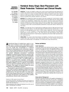
Employing the numerical models enables to calculate stresses in an artery into which different stents were inserted; each stent has a suitable periodical structure with a uniform beams cross section. In principle, it is possible to apply this method for a diversity of stents, but in this section we calculate only the stresses developed in an artery as a result of inserting a Micro II type stent into it. This stent was selected because we have the data regarding his stiffness and geometrical dimensions. The results showed that the stiffness of the stent increases when its diameter decreases. Hence for various cases in which stents of different sizes are inserted, it is necessary to pay attention to the appropriate value of the stent’s stiffness. In the following case the artery was considered as being a hollow, two layered entity, with non linear and hyper elastic properties. A. Potential Damage Factor for a Micro II Type Stent In this model, we present the results for a Micro II type stent (Fig. 8). The radial stiffness was computed relying on the data in the cited paper by Schrader and Beyar (1998), see Fig. 9. From the above stress-strain diagram one obtains
4
radial stiffness value of 1 ⋅ 106 N / m 2 for a 3 mm diameter stent and 0.7 ⋅106 N / m2 for a 4 mm diameter stent.
Fig. 8 - Micro II stent (Serruys and Kutryk, 1998).
Fig. 9 - Stress – strain diagram for Micro II stent expanded to 3mm (*line) and 4mm (+-line), and after relaxation (dash-dotted O-line) (Schrader and Beyar, 1998)
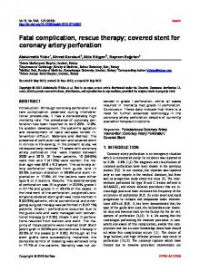
The values of the Potential Damage Factor for the collection of cases, in which the artery’s blocking percentage and stent to artery mismatch values varies, are presented in Fig. 10. A surface describes the Potential Damage Factor for a stent inflated to 3mm diameter wherein the diameter of the artery after recoil is smaller than the stent’s one by a value in the range of 0.1 to 0.5mm. The blocking percentages of the artery selected for the same assemblage of cases was 15% to 90%.
Finally, use was made of the two dimensional model for examining additional stents, e.g. those with periodic structures that were inserted into arteries, where their geometry and radial stiffness were known. From the results obtained it was possible to conclude that: For arteries with small diameters – larger stresses are obtained relative to the case of arteries with larger cross section (for identical blocking and radial mismatch). A similar phenomenon was reported by Brand et al. [8, 9] wherein they treated different stents. The results we obtained can be applied by the designers of stent as well as by medical personnel for choosing the most suitable stent for a specific patient. Future research should use the match that was found in order to obtain results for the Potential Damage Factor in the case of asymmetric artery stenosis.
REFERENCES 1.
2. 3.
4.
5.
6.
Fig. 10 - Potential Damage Factor diagram for a Micro II type 3 mm stent inserted into an artery as a function of stent to artery radial mismatch and artery’s blocking percentage.
V. SUMMARY AND CONCLUSIONS The goal of this research is to suggest a numerical approach for calculating the contact stresses applied to the wall of the artery following the insertion of a net structured stent into it. Representation of the interface pressure between stent and artery was performed using a dimensionless parameter, the Damage Factor (DF). Two kinds of numeric models were examined, two dimensional and three dimensional, and a good match was obtained between them. This match enables us to compute the stresses using the two dimensional model, which is simpler and much faster in computing the results as compared to the three dimensional model.
Numerical Models of an Artery with Different Stent Types
7.
8.
9.
Schrader, C. S., and Beyar, R., 1998, Evaluation of the Compressive Mechanical Properties of Endoluminal Metal Stents, Cathet Cardiovasc. Diagn., 44, pp. 179–187. De Belder, A., and Thomas, M. R., 1998, The Pathophysiology and Treatment of In-stent Restenosis, Stent, 1(3), pp. 74–82. Akiyama, T., Di Mario, C., Reimers, B., Ferraro, M., Moussa, I., Blengino, S., and Colombo, A., 1997, Does the High-Pressure Stent Expansion Induce More Restenosis? J. Am. Coll. Cardiol., 29, p. 368A. Oesterle, S. N., Whitbourn, R., Fitzgerald, P. J., Yeung, A. C., Stertzer, S. H., Dake, M. D., Yock, P. G., and Virmani, R., 1997, The Stent Decade: 1987 to 1997, Am. Heart J., 136, pp. 578–599. Rachev, A., Manoach, E., Berry, J., and Moore, J. E., Jr., 2000, A Model of Stress-Induced Geometrical Remodeling of Vessel Segments Adjacent to Stents and Artery/Graft Anastomoses, J. Theor. Biol., 206, pp. 429–443. Holzapfel, G. A., Stadler, M., and Schulze-Bauer, C. A.J., 2002, A Layer- Specific Three-Dimensional Model for the Simulation of Balloon Angioplasty using Magnetic Resonance Imaging and Mechanical Testing, Ann. Biomed. Eng., 30, pp. 753–767. Holzapfel, G. A., Stadler, M., Changes in the Mechanical Environment of Stenotic Arteries During Interaction With Stents: Computational Assessment of Parametric Stent Designs, J. Biomech. Eng., February 2005, Volume 127, Issue 1, 166 (15 pages). Brand M., Ryvkin M., Einav S., The SciMED RADIUS Stent-Artery Interaction, Proceedings of the 9th Biennial ASME Conference on Engineering Systems Design and Analysis, ESDA08, 2008, Haifa, Israel. Brand M., Ryvkin M., Einav S. and Slepyan L., 2005, The Cardiocoil Stent-Artery Interaction, Journal of Biomechanical Engineering, 127, pp 337-344. Author: Institute: Street: City: Country: Email:
Moshe Brand Ariel University Center of Samaria P.O.B. 3 Ariel Israel
[email protected]