Both local and global hydrodynamic ship design optimization problems are ... Examples of real ship hydrodynamic design optimization cases are given, re-.
Numerical Optimization Methods for Ship Hydrodynamic Design Emilio F. Campana1 (V), Daniele Peri1 (V), Yusuke Tahara2 (M), Manivannan Kandasamy3 (V), and Frederick Stern3 (M) 1
INSEAN — Italian Ship Model Basin, Rome, Italy NMRI — National Maritime Research Institute, Tokyo, Japan 3 IIHR — Hydroscience & Engineering, University of Iowa, USA 2
The use of computational methods in design engineering is growing rapidly at all stages of the design process, with the final goal of a substantial reduction of the cost and time for the development of a design. Simulations and optimization algorithms can be combined together into what is known as Simulation-Based Design (SBD) techniques. Using these tools the designers may find the minimum of some user defined objective functions with constraints, under the general mathematical framework of a Non-Linear Programming problem. There are problems of course: computational complexity, noise, robustness and accuracy of the numerical simulations, flexibility in the use of these tools; all these issues will have to be solved before the SBD methodology can become more widespread. In the paper, some derivative-based algorithms and methods are initially described, including efficient ways to compute the gradient of the objective function. Derivative-free methods — such as genetic algorithms and swarm methods—are then described and compared on both algebraic tests and on hydrodynamic design problems. Both local and global hydrodynamic ship design optimization problems are addressed, defined in either a single- or a multi-objective formulation framework. Methods for reducing the computational expense are presented. Metamodels (or surrogated models) are a rigorous framework for optimizing expensive computer simulations through the use of inexpensive approximations of expensive analysis codes. The Variable Fidelity idea tries instead to alleviate the computational expense of relying exclusively on high-fidelity models by taking advantage of well-established engineering approximation concepts. Examples of real ship hydrodynamic design optimization cases are given, reporting results mostly collected through a series of projects funded by the Office of Naval Research . Whenever possible, an experimental check of the success of the optimization process is always advisable. Several examples of this testing activity are reported in the paper—one is illustrated by the two pictures at the top of this page, which show the wave pattern close to the sonar dome of an Italian Navy Anti-Submarine Warfare corvette: left, the original design; right, the optimized one.
30
Numerical Optimization Methods for Ship Hydrodynamic Design
1
INTRODUCTION TO SIMULATIONBASED DESIGN METHODS
algorithms, and the ever increasing computational capacity. In addition to simulation codes and optimization algorithms, a third element is fundamental in the development of a SBD framework for shape optimization—a geometry-modeling method that provides the necessary link between the design variables (and their variations) and the deformation of the body shape. When an analysis tool is based on the solution of a Partial Differential Equation (PDE) on a volume grid surrounding a complex geometry, developing a geometry-modeling method can be a difficult task and require attention to detail. Flexibility of the modeling method may greatly affect the freedom of an optimizer to explore the design space. The aim of this paper is to highlight some important factors of the many relevant issues in the context of SBD applied to ship hydrodynamic design, rather than give a detailed review of SBD methods. Historically, in the naval hydrodynamic context the focus was initially on minimizing total resistance, which was evaluated by using wave resistance via the thin-ship theory plus a term that attempted to account for the frictional resistance. The papers by Webster & Wehausen [102] and Lin, et al. [52] seem to be among the earliest papers dealing with the problem of producing three-dimensional, ship forms of low resistance. The ship geometry was approximated via finite Fourier series and the minimization approach was based on the method of Lagrange multipliers [30]. Baba [4] proposed a method based on the knowledge of the wave spectrum of the initial ship design and on the successive superposition of a thin ship which would reduce the wave-making resistance. Using a thin-ship approximation and the method of Lagrange multipliers, Hsiung [38] and Hsiung & Shenyan [39], initially solved the problem for wave resistance and subsequently for total resistance, using the ITTC 1957 correlation line formula to add the viscous part, which resulted in a “hammer-head shark”form similar to those obtained by Lin, et al. [52]. Some experiments were also carried out on the optimized shapes. Salvesen, et al. [83], Papanikolaou & Androulakakis [68] and Scragg, et al. [85] optimized SWATH hull forms using the Lagrange multipliers method. Salvesen, et al. [83] estimated the viscous contribution to the resistance by using a simple boundary-layer approach. Additionally, Papanikolaou & Androulakakis [68] and Scragg, et al. [85] carried out experiments on the optimized hulls to establish the success of the optimization procedure; the hull form of Scragg, et al. [85] was actually built full scale. In the late 1980s, Pironneau [79] and Jameson
Optimization means much more than improvement. Nevertheless, many researchers and design engineers still employ the terminology optimization when what they mean in practice is that after starting from a non-satisfactory configuration, they have tried two or three other ones and chosen at the end the best one. This is undoubtedly related to optimization, but in a minimal sense. In the present paper optimization means the use of some minimization algorithm to find the best possible solution (in some defined sense) constrained by appropriate conditions. More specifically, we will focus on optimization methods driven by numerical simulations applied to the optimal hydrodynamic design of ships. The growing reliance on rigorous computational methods in engineering at all stages of the design process seems to be an irreversible process, the final goal being to reduce the time and cost of both design development and standard testing activities (which currently are very time consuming and expensive to run). By using computational methods, candidate designs are numerically evaluated to establish their respective merits. To date, though, this way of using numerical simulations has had a more dramatic impact on the design process, rather than on the design per se, which still relies greatly on the experience of the designer and on heuristic procedures i.e., on the art of engineering. Additionally, the complexity of modern engineering systems makes the use of heuristic methods alone increasingly challenging: “Radically new designs present a difficult problem because designers cannot rely on historical databases. Moreover, some design areas experience a loss of immensely valuable design knowledge with the retirement of designers. There is also a realization that meeting a minimal set of requirements may not suffice to ensure success of new designs.” (Alexandrov [1]). The above drawbacks make the use of Simulation-Based Design (SBD) techniques—which combine (i) simulations, (ii) optimization algorithms and (iii) grid and geometry deformation methods— much more feasible. Design performance feeds an algorithm capable of finding the minimum of some user-defined objective functions and constraints, under the general mathematical framework of a NonLinear Programming problem. The design performance is evaluated by adopting some numerical code chosen by the user. What enables the pursuit of SBD is the development of better numerical models of the governing disciplines, faster optimization
Numerical Optimization Methods for Ship Hydrodynamic Design
2
31
NOMENCLATURE √ Fr = Froude Number = U/ gL Re = Reynolds Number = U L/ν vki = Velocity of the i-th particle of the swarm at the k-th step X = Design variable vector x, y, z = Coordinate system, with x aft, y to starboard, and z upward, coordinate of a field point xik = i-th particle of the swarm at the k-th step wk = Particle’s inertia at the k-th step β(x) = Correction factor for Variable Fidelity ∆ = Ship’s displacement δxi = Finite perturbation on the i-th design parameter γ = Variogram of the objective function λi = Weights in the Kriging metamodel λl = Lagrangian multipliers of the penalty function ξ = Vector of the N design parameters ρ = Fluid density σ(Q) = Source strength at a generic point Q Φ = Total Velocity potential ϕ = Perturbation potential φL (x) = Low Fidelity model of the objective function φH (x) = High Fidelity model of the objective function χ = Constriction factor
B Cf Ct Ct∗ Cw c1 , c2 fi G GM g gw Nbody Nf s Ntot p pi pb
x21
(15)
− 10
The feasible set (shown in Fig. 46) is represented by the portion of space x21 − 10 x21
+
x22
M cm j ≤ gj (X) ≤ cj ,
(16)
j = 1, . . . , l,
(17)
where the gj (X) describes some performance as a function of the design variables—for instance, the ship’s total resistance at a given speed, or the requirements concerning the stability of the ship— which the designer may decide to confine within a suitable range. The constraints in Eq. 17, ap-
>4
(the resulting feasible set is shown in Fig. 47). In this second example, which will also be helpful in the discussion about local and global optimization
68
i = 1, . . . , N,
Numerical Optimization Methods for Ship Hydrodynamic Design
39
flexible as possible in order to allow the analysis of a wide range of possible solutions. Details of the B´ ezi´ er-patch approach A simple way to deform the ship geometry is to superimpose a B´ezi´er patch on the hull that gradually reduces to zero perturbation when approaching the unmodified portion of the hull. The patch is controlled by a B´ezi´er frame of m × n nodes, which are related to the patch via: YB (u, v) =
n X m X
In,i (u) Jm,j (v) pi,j ,
(18)
i=0 j=0
where YB are the coordinates of the B´ezi´er surface, u and v are nondimensional parameters along the x- and z-directions, pi,j are the y-coordinates of the B´ezi´er frame nodes and � � n In,i = (1 − u)n−i ui i � � m Jm,j = (1 − v)m−j v j . j
Fig. 47 Disjoint feasible set resulting from the example in Eq. (16). The x1 - and x2 -axes are not the same scale. The feasible set is represented by the shaded region. plied to Π, single out the feasible set, S, in the N -dimensional design space, i.e., S ⊂ Π is the set of design solutions that satisfy all the constraints. The shape of the feasible set, S, may result in a non-convex, non-connected region; this represents a crucial difficulty in the solution of the optimization problem. In fact, some optimization algorithms produce a convergent sequence of trial solutions along a nearly-continuous path, and are unable to jump from one side to another of a non-connected feasible set. As a consequence, this class of algorithms may be highly penalized by the selection of the initial solution, because the starting point may be in the wrong portion of the feasible set. Furthermore, if the feasible set is non-convex, they may be stuck in a corner, unable to proceed toward the optimal point. In general, constraints need to be accounted for, for proper treatment in an optimization problem, the final goal being the translation of a constrained problem into an unconstrained one.
Since the B´ezi´er surface is defined on a 2D-unit square, we need to map the hull surface onto an unit square. To do that, we can use the coordinate lines provided by the regular structured grid commonly used in CFD codes to digitalize the hull surface. A structured regular (N × M ) grid defines two indexes for each grid point, (say from 1 to N and from 1 to M ). We can normalize these values by the maximum value so that each grid point is now associated with a pair of real numbers included in [0 : 1]. The B´ezi´er surface is defined by a net built on this unit square. Since the B´ezi´er surface is defined as a continuous function in the selected portion of the 2D space, we can compute the height of this surface on every point of the unit square, in particular those coordinates which are associated with the grid points. These values are now simply superimposed on the y-offsets of the hull to obtain the modified geometry via
APPENDIX B—PARAMETRIZATION
YHmod = YH o (u, v) + YB (u, v).
In deforming the geometry of a hull form, one has to follow some general guidelines: • if the modified part is a subset of the entire hull, the modified geometry has to join the original design without discontinuities in the first and second derivative; • the number of design variables should be kept as small as possible to minimize the number of evaluations of the gradient of the objective function, but . . . • . . . the hull modification algorithm should be as
(19)
More patches can be used allowing for a complete modification of the geometry along the three directions. Details on the Free-Form Deformation (FFD) approach The FFD, introduced by Sederberg and Parry [86] in computer graphics, is a very flexible approach to deform a 3D object, whose geometry is given by points. This approach can be essentially reduced to
Numerical Optimization Methods for Ship Hydrodynamic Design
40
69
6
J Mar Sci Technol (2008) 13:䊏䊏–䊏䊏
a 4D-B´ezi´erOnpatch to hand, be applied to the hull surface. the other the LPt grid approach is a rational way to previous uniformly distribute points inside a prescribed In fact, in the superposition approach, we of the designfunction space. A sequence points uniare usingportion a perturbation mappingof an unit formly by spaced easily determined bywe using tabular data square defined theisnodal indexes. If now define reported in Statnikov and Matusov.33 The criteria gova box surrounding the hull surface, we can define a erning the choice of the position of the sampling point B´ezi´er polynomial inside this 3D in space, and the tabular datadomain, as well, isproducing that for every a scalar prescribed function volume of the (smaller 3D space. This function, than the analyzing region) placed into the investigated portion of the design space; defined as the number nof included m X l points do not change with the XX position of the control region. The limitations coming F (u,from v, w) = I space (u)dimension less than 20 the tabular data33 are:n,i (20) i=0 j=0 k=0 and number of points less than 65 536. These limits are fully compatible the class problems × Jwith Kl,kof (w) pi,j,k , we are going m,j (v) to solve.
with the same structure as Eq. 18, could represent 2.2 Geometry and a grid manipulation the displacement along prescribed direction, and is applied to every hull point in order to produce Tools for geometry modeling (and its necessary sequel, the deformed geometry. The definition of coeffiautomatic grid deformation) are another relevant SBD cients is similar to those for Equation 18, and comes component. An efficient and flexible way to modify the again from the theory ofisthe B´ezi´ er apolynomials. geometry of the body necessary for full investigation The B´ezi´ er the function is defined box placed of design variable spaceinside and a the successful optimization.object Techniques be versatile to comdescribe around the to beshould deformed, andenough we can broad variety of three-dimensional conpute the adeformation oncomplex every point inside this(3D) box. fi gurations and be suffi ciently compact so as to use as The deformation is not defined outside.
few variables as possible. Once the optimization algorithm obtains the vector with the new design variable Details values, on the Morphing approach we have to spread the deformation over the body In the morphing thevolume deformation is surface and the approach, computational grid. Flexible producedmethods starting from a number of prescribed hull are the superposition of several basic forms (morphing techniques)weorneed the expansion/reduction shapes. As a consequence, P designs for the of basic geometry. Another method for geometry same hull, and we also need capable a computational grid is through application of CAD systems. In the with the modeling same subdivision. We are going to adopt present study, two approaches are investigated, i.e. a a mapping between the grid points of the different CAD-based approach and an additive perturbation designs based on the grid topology. If we have a (CAD-free) method.
suite of grids, all subdivided into (N × M ) intervals, Geometry method-A: CAD-based approach we can pick a generic (i, j) point on the grid, thus defining
To modify the ship geometry, a CAD-based hull form
adopted. X(i, j) =modifi w1 Xcation + w2 Xwas j) + · · Two · + wapproaches 1 (i, j)method 2 (i, p Xp (i, j),are possible, i.e., CAD direct control and CAD emulation
plus the approaches. condition Both approaches were successfully demon-
D2
15 strated by the present authors3,5 and others.1 In the P X present work, the CAD emulation approach is used. As wi = 1. shown in Fig. 4, a module is implemented in order to i=1 emulate CAD operation handling with mathematical surface modeling. This approach an advantage Here Xk (i, j) represents the vector ofoffers coordinates of overpoint the CAD approach (i, forj), complete the generic withdirect gridcontrol coordinates, beindependence from the CAD system, i.e., designers are longing to the kth grid. This approach produces able to use any CAD system and give/receive initial/optia linear mized blending among the available geometries, hull form geometry in initial graphics exchange
which obviously limits the possible shapes implicitly defined by the designs provided. However, we can 13 simply investigate some specific solutions by means of a really limited number of parameters (1 − P , due to the condition of the sum of weights equal to 1). The transition from one shape to another can also JMST264.indd 6 be different than the linear one, and the reference grid can be also of different topology from design to design, allowing a larger variety of hull shapes.
70
Opt im izer Design Va r .
Object ive F u n ct ion
CAD Con st r a in t F u n ct ion IGE S Con t r ol
Su r fa ce Gr id Gen er a t ion
CF D
A
C
B
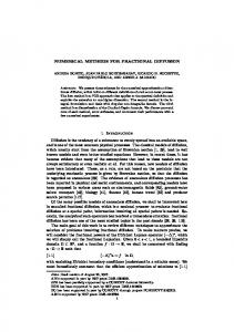
Fig. 4. Implementation of computer-aided design (CAD)-based hull form in the optimizationofenvironment. IGES, hullFig. 48modification Implementation CAD-based initial graphics exchange specification form modification in the optimization environment (IGES, Initial Graphics Exchange Specification).
specification (IGES) format data. For example, the non- 16 CAD-based approach uniform rational B-spline (NURBS) is widely used in To modify the ship geometry, a CAD-based CAD systems for hull-form design as IGES entity 128. hull-form method given was by: adopted. Two A NURBS modification surface is mathematically approaches are possible, i.e., CAD direct control and n m CAD emulation approaches. Both approaches were N u N v w P ( ) ( ) ∑ ∑ i, p j ,q i, j i, j i =0 j =0 successfully authors S( u, v ) = n mdemonstrated by the present (3) [97] and others. emulation approach (v ) wCAD ∑ ∑ Ni ,Here, p ( u ) N j ,qthe i, j i =0 j =0 is reported. As shown in Fig. 48, a module is imwhere u and in v are parameters; Ni,p and Ni,q are CAD normalplemented order to emulate manual manipized B-spline basis functions of degree p and This q in the u ulation of the mathematical surface. approach and v directions, respectively; Pi,j are location vectors of offers an advantage over the CAD direct-control apthe control points; and wi,j are weights. Finally, the proach frompoints, the CAD surface isfor deficomplete ned by (n +independence 1) × (m + 1) control system, i.e.,knot designers are weights, and vectors of n +able p + 2 to anduse m +any q + 2CAD ele- sysments in the u and v directions, respectively. A modified hulltem and give and receive the initial, optimized surface is defined in in Initial correspondence to new locationSpeciform geometry Graphics Exchange n , so that: vectors P fication (IGES) data format. A NURBS surface is given mathematically by: Pin, j = Pio, j + δ Pi , j (4) Pn Pm i=0 j=0 Ni,p (u)Nj,q (v)wi,j Pi,j where Po v) and=d P are the P P S(u, n original m and displacement loca- , i,p (u)Nj,q i,j tion vectors. d P can be of (v)w the optii=0the design j=0 Nvariables mization problem.
where u and v are the parameters; Ni,p and Nj,q are normalized B-spline basis approach functions of free degree p and Geometry method-B: CAD-free using qform in the u and(FFD) v directions, respectively; Pi,j are deformation the vectors of the control points; and wi,j are the With this approach, the use of CAD or parameterization weights. of the hull surface is avoided and the deformation of the Finally, the surface is defined by [(n+1)(m+1)] shape is defined and controlled by using a few control control points and weights, and knot vectors of points, much fewer than the number of nodes used for n + p + 2 and m + q + 2 elements in the u and v directions, respectively. A modified surface is defined corresponding to new location vectors, P n , so that: n 0 Pi,j = Pi,j + δPi,j , 0 6:20:24 PM where Pi,j and δPi,j are the original and 2/19/2008 displacement location vectors. δPi,j can be the design variables of the optimization problem.
Numerical Optimization Methods for Ship Hydrodynamic Design
41
APPENDIX C—A TWO-DISCIPLINE MDO PROBLEM
fore given by the simultaneous system of equations: � a1 = A1 (s, l1 , a2 ) (21) a2 = A2 (s, l2 , a1 ),
We introduce here a simple, two-discipline MDO problem (∆1 and ∆2 ): the hydroelastic coupling between hydrodynamics (∆1 ) and structural analysis (∆2 ) for the keel fin of a sailing yacht in steady forward motion with a drift and a yaw angle as in [12]. The two disciplinary systems are the basic elements of the MDO problem. We assume that each discipline is based on a disciplinary analysis (from simple algebraic formulas to complex PDEs) that may be schematically depicted as an input-output relation: s, li , pi -
Disciplinary Analysis ∆i
where the solution of the discipline ∆1 gives the input for the discipline analysis ∆2 and vice versa, therefore implicitly defining a1 and a2 as functions of (s, l1 , l2 ). Solving the fully coupled system Eq. (21) leads to a full multidisciplinary analysis (MDA). The solution is in this case a consistent solution that satisfies both disciplines. Again, if ∆1 represents hydrodynamic analysis of the flow around the fin keel and ∆2 represents structural analysis of the fin, a1 and a2 may represent the flow field near the keel and the deformed shape of the fin keel due to structural response and hydrodynamic loads, respectively. The calculation of the flow field a1 requires the shape of the fin keel, which is contained in a2 , while the calculation of the fin deformation a2 requires the hydrodynamic loads, contained in a1 . The formulation of a two-discipline MDO problem involves the previous definitions but in the framework of an optimization problem. Up to now we were just looking for a multidisciplinary equilibrium between the two disciplines. The most natural optimization problem formulation is to impose an optimizer over the MDA Eq. (21). In fact, this approach has been commonplace in engineering for many years. The formulation is depicted as follows:
-ai
The input of each discipline are a set of design variables, (s, li ), and parameters, pi , and the analysis produces a set of outputs, ai . The system-level design variables, s, are those shared by both disciplines. The disciplinary design variables, l1 and l2 , are local to ∆1 and ∆2 , respectively. Parameters, pi , are derived from the analysis outputs, aj , j 6= i, of the other discipline. They are not directly manipulated by the designer in ∆i . In our hydroelastic example, the input, p1 , from structures to hydrodynamics would include the fin keel shape, while the input, p2 , from hydrodynamics to structures would include the hydrodynamic loads. The disciplinary analyses have the functional form ai = Ai (s, li , pi ). A1 and A2 are assumed to be independently solvable. In our hydroelastic example, given the shape of the fin (the values p1 ) one can solve A1 and obtain the flow field and the pressure around the fin (a1 ) and analogously for A2 . Now, in the context of the MDO problem, the coupled Multidisciplinary Analysis System (MDA) reflects the physical requirement that a solution simultaneously satisfy the two disciplinary analyses. The input parameters, pi , for each discipline are now required to correspond to some (or all) of the outputs, aj , from the other disciplinary analysis. Schematically, we have:
s, l1
s, l2
s, l1
s, l2
�� - Disciplinary Analysis ∆1 - a1 � �� k � Q � Q + Q �� � Q - Disciplinary Analysis ∆ - a2 2 �� Q a1 Q Q
a2�� � s Q
min s, l1 , l2 subject to
�� - Disciplinary Analysis ∆1 - a1 � �� k � Q � Q + Q �� � Q - Disciplinary Analysis ∆ - a2 2 �� The multidisciplinary analysis system is there-
+ � f (s, a1 , a2 ) g1 (s, l1 , a1 ) ≤ 0 g2 (s, l2 , a2 ) ≤ 0
where g1 and g2 are the disciplinary design constraints. Many different MDO formulations exist that can be built starting from the above formulation. Recent efforts in analysis and development of problem formulations for MDO can be found in the recent, special issue that the journal, Optimization and Engineering, dedicated to MDO (see [1] for the complete reference).
Numerical Optimization Methods for Ship Hydrodynamic Design
42
71
Discussion Dane Hendrix, Member I congratulate the authors on compiling a remarkable collection of hydrodynamic optimizations. This collection is remarkable not just for the variety of cases addressed but more for the variety of tools used to attack those problems. I am especially interested in learning more about meta-models and intend to follow up on some of the references you provide. There are a number of questions I could ask about the work presented, but I will restrict myself to just a few more general questions. (1) Is there a reason that you don't use a series of gradient method optimizations to generate a Pareto front? It seems that for smooth objective functions this would be a more efficient method than using a global optimization method. (2) Most of the examples you give are point designs. That is, the objective is for a single speed or wave frequency. Do you have any experience that would indicate that the optimization process is better behaved when you use an objective function that addresses a range of conditions? My experience is that this reduces the problems of local minima keeping a descent method from finding a global minima (Percival, 2001). (3) I find it helpful to think of optimization as consisting of three parts: - the geometry modification - the objective function evaluation - the optimization algorithm
(3b) In one case where you investigated two different objective functions for the application to a sailing yacht keel, you found that for the conditions investigated that the initial gradient from your low fidelity model (potential flow) was almost exactly opposite to that given by your high fidelity model (RANS). Is this because of significant separation in the original geometry? Or was the low fidelity potential model ignoring lift? Or was there some other characteristic of the flow that led to this result? (3c) Have you looked at the effect of different forms of geometry modification on the optimization result? In the HSSL SWATH example you discuss using initial sensitivity studies to down select design variables. Could you offer some more information on how this was done? (3d) Do you have any opinion on whether increasing the number of design variables for different types of hull parameterizations converge to the same result? (4) What are the sources of the differences in the 5415 optimizations presented (solver, hull discretization, how RAOs are evaluated, other)? Again congratulations on an excellent paper and I look forward to your responses.
Percival, S., Hendrix, D., and Noblesse, F. 2001 "Hydrodynamic optimization of ship hull forms," App. Ocean Research, 23, pp. 337-355.
John Kuhn, Member (3a) You have presented one very good example of using different optimization algorithms for the same problem in the hull-form optimization for seakeeping section. Here you use three different optimization algorithms to analyze the same problem. From Tables 1 and 2 it is not clear that they have all converged and the intermediate results presented in Figure 9 suggest that they may not even be converging toward the same minima. In Table 2, FILLDIR appears to have produced a better result than DDFPSO or DIRECT while in Table 1, the opposite is true. Does this say something about the initial efficiency of each of these methods? Would it be instructive to push each of these algorithms to convergence?
72
The authors have made a significant contribution by presenting a broad assortment of techniques that cover many important issues in hydrodynamic optimization. In addition, they have demonstrated that large performance gains are possible if pertinent aspects of a design are able to be changed with sufficient freedom by the optimization process. Many elements of the paper are worthy of discussion, but in the interest of brevity I will restrict my attention to only one item: seakeeping optimization. The example in the paper based on heave motion of the S175 containership in head seas reminds me of an issue that we confronted recently. Specifically, we have found that it can be important to include a range of
Numerical Optimization Methods for Ship Hydrodynamic Design
headings in work of this sort, and I was wondering if any analysis was done to assess the way in which the heave optimum for head seas performs at other headings, or in other degrees of freedom (i.e., roll or pitch). In one of our recent studies we minimized roll motion in beam seas. A significant improvement was achieved in beam seas, but the roll became worse at another heading. Although roll may be more sensitive than heave in this regard, the results that we found illustrate a basic issue, so I will summarize some of our findings to motivate discussion. Briefly, we minimized the root mean square (RMS) roll motion of a large displacement ship in sea state 5 beam seas with 20 knots forward speed. The problem contained an assortment of practical design constraints, and was solved with the SHAPE optimization code (Kuhn et al., 2007). All of the seakeeping calculations for the objective function were done with the Large Amplitude Motions Program (LAMP; Lin et al., 1999). The RMS roll was reduced from 6º (for the baseline) to 4.2º (for the optimization), which is a 30% reduction. However, performance at other headings that were not included in the optimization varied in both favorable and unfavorable directions, as shown in Figure 1.
Figure 1 Results for optimum based on roll minimization at 90º heading (0º is following seas, 180º is head seas Although the roll motion declined significantly for the single heading that was included in the optimization (i.e., 90º), it became considerably more severe at the 60º heading (which was not included in the optimization). In fact, it looks like the most adverse heading for the optimum has shifted to somewhere between 60º and 90º, but we did not examine any intermediate headings in an attempt to find the new peak.
We decided to include multiple operating conditions in the optimization as a consequence of this behavior. One could, in principle, approach this as a multiobjective problem with individual objective functions for every operational condition of interest. However, this could entail a significant matrix of headings, speeds, and sea states. The matrix should also include multiple degrees of freedom (i.e., heave, pitch, and roll). The overall matrix could easily become very large, making the use of Pareto optimality based on all such objectives an onerous chore. There could easily be 30 or 40 objectives (or even more). As an alternative, we have found it effective to use constraints for those conditions that are not handled as an objective. Thus far, this has only been investigated for local optimization in the vicinity of the baseline design, but it has produced some interesting results. For example, it is possible to constrain the roll motion for headings other than beam seas, while minimizing roll in beam seas. This yields the result shown in Figure 2. Note that this figure also contains the result given in the previous figure to facilitate easy comparison.
Figure 2 Effect of constraints on roll for headings not included in objective function As shown in the figure, the roll constraints mitigate growth in roll at the 60º heading, and a 15º reduction in roll is still possible at the 90º heading. The constraints have arbitrarily chosen bounds for this example, but they could be based on standardized criteria for motions, if desired. This is just one example of what can be done. To be safe, however, it would probably be prudent to include constraints on headings that are more closely clustered around the peak than has been done for this example.
Numerical Optimization Methods for Ship Hydrodynamic Design
73
Because seakeeping is a vibration problem, sensitivity to operational conditions is not surprising. They determine the excitation of the motion. An optimizer could easily “tune” a design in ways that improve performance for the conditions that are not included in the optimization. This may be most acute for cases with forward speed, because the frequency of excitation shifts with changes in heading. Some degrees of freedom may be more sensitive to this issue than others, and more research is needed to fully understand it. Dealing with problems like this entails a large amount of computational (and logistical) effort. Your paper already provides valuable guidance in this regard, but any additional comments or observations that you have about practical ways to handle a full permutation of headings, speeds, and degrees of freedom for seakeeping optimization would be most welcome. And, of course, it is also desirable to simultaneously include other design metrics in the optimization process, such as drag or construction producibility. Perhaps the answer involves a combination of Pareto optimality for a manageable number of objective functions based on the most critical metrics, combined with constraints to control behavior for other metrics that are not contained in any other objective functions. Once again, your paper contains many valuable findings in a complex area. Thank you for making this contribution to our field.
References Kuhn, J. C., K. L. Chevalier, E. C. Schlageter, S. A. Scragg, and D. C. Wyatt. 2007 The use of linear programming and basis function for hull-form optimization, 9th International Conference on Numerical Ship Hydrodynamics, Ann Arbor, Michigan. Lin, W. M., S. Zhang, K. Weems, and D. K. P. Yue. 1999 A mixed source formulation for nonlinear shipmotion and wave-load simulations. 7th International Conference on Numerical Ship Hydrodynamics, Nantes, France.
74
Authors’ Closure The authors thank Dr. Hendrix for the stimulating discussion. Question 1 Is there a reason that you don't use a series of gradient method optimizations to generate a Pareto front? It seems that for smooth objective functions this would be a more efficient method than using a global optimization method. Gradient-based optimization methods are extremely accurate and fast for local, single-objective optimization problems. As Dr. Hendrix suggests in his question, if one needs to solve a multiobjective problem and wants to use a gradient-based algorithm, the different objective functions have to be aggregated into a single merit function f*:
Nf
f*(x) = ∑ wifi(x) i=1
where Nf is the number of objective functions and wi are the corresponding weights of the different objectives fi. With this approach, one can find a single point on the Pareto front (it should be mentioned anyhow that it is not guaranteed that the local minimum identified by the gradient method belongs to the Pareto set). To identify more solutions – belonging to the Pareto set one hopes - one therefore needs to perform repeated gradient-based searches (i) starting from different initial designs and (ii) with different combination weights wi for the merit function. This is certainly possible and it can be easily done. There are of course also good reasons to develop true global optimization methods for multiobjective problems. To quote an excellent reference on multiobjective methods (Statnikov and Matusov, 1995): “Numerous attempts to construct a generalized criterion in the form of a combination of particular criteria proved to be fruitless. By cramming a multicriteria problem into the Procrustean bed of a single-criterion one, we replace the initial problem with a different one that has little in common with the original problem.” We have no direct experience with the procedure suggested in the question. However, in our experience, multistart gradient-based methods for single-objective problems are much less accurate than global optimization methods. An example is given in the following picture,
Numerical Optimization Methods for Ship Hydrodynamic Design
which refers to the solution of a single optimization problem, namely the design optimization problem for the Ship S175. The objective function F was the RAOs peak value for the heave motion in head seas (at 16 knots) and six design variables were used for the solution. Geometrical constraints were imposed on the minimum and maximum beam and on the ship displacement, and a simple strip-theory code was used as analysis tool for computing F. In Figure 1 the solutions obtained with a number of different algorithms - local and global - are presented. The RAO's peak is reduced by using all the optimization algorithms: among local solutions, the one obtained with a multistart gradient method is arguably the best one. It is, however, clear that all the global methods tested are superior to the multistart.
Figure 1 Heave RAO in head seas at 16 knots: local optimization procedures are able to improve the original design, whereas global optimization techniques are successful in finding a much better design!
Question 2 Most of the examples you give are point designs. That is, the objective is for a single speed or wave frequency. Do you have any experience that would indicate that the optimization process is better behaved when you use an objective function that addresses a range of conditions? My experience is that this reduces the problems of local minima keeping a descent method from finding a global minima. As far as we understand, in principle there is no reason for which an optimization process should be better behaved when using a multipoint objective function,
addressing a range of conditions. Conversely, we would agree on that a multipoint solution is more robust, that is the performances of a single point design tend to drop in off-design conditions. Indeed, techniques for robust optimization, of the type described in the paper, address exactly this problem. Question 3a You have presented one very good example of using different optimization algorithms for the same problem in the hull-form optimization for seakeeping section. Here you use three different optimization algorithms to analyze the same problem. From Tables 1 and 2 is it not clear that they have all converged and the intermediate results presented in Figure 9 suggest that they may not even be converging toward the same minima. In Table 2, FILLDIR appears to have produced a better result than DDFPSO or DIRECT while in Table 1, the opposite is true. Does this say something about the initial efficiency of each of these methods? Would it be instructive to push each of these algorithms to convergence? In Tables 1 and 2 we used a fixed number of objective function evaluations to stop the algorithms: 100 (1000) times the number of design variables, i.e., 600 (6000) objective function evaluations, respectively. What is clear from Table 1 is that DDFPSO and DIRECT show close performances when one has only a reduced number of objective function evaluations available; indeed, they obtain nearly the same result in terms of design variable values and objective function reduction. FILLDIR is faster but converges to a slightly less attractive solution (anyhow the loss in ship performance with respect to the other two algorithms is only about 3.5%). When more objective function evaluations are available we got a reversed situation: DDPFSO is the best: the solution is almost coincident with the other two but the convergence is faster. Anyhow it is clear that different global methods can converge to different results; indeed, there is no mathematical proof that, for non-convex problems, one has reached the absolute global minimum. Question 3b In one case where you investigated two different objective functions for the application to a sailing yacht keel, you found that for the conditions investigated that the initial gradient from your low fidelity model (potential flow) was almost exactly opposite to that given by your high fidelity model (RANS). Is this because of significant separation in the original geometry? Or was the low fidelity potential
Numerical Optimization Methods for Ship Hydrodynamic Design
75
model ignoring lift? Or was there some other characteristic of the flow that led to this result? The example reported has been designed for illustrating the qualities of the Variable Fidelity Modeling, and was selected as a good example of the differences between two different models. The low fidelity potential model includes straight trailing vortices living the fin keel at an undetermined angle (Bollay W., 1936). In the example, however, the bulb geometry of the yacht keel is changing, and the Laplace solver is not able to produce accurate results in these conditions, because the frictional resistance is brutally estimated by considering the thin plate resistance, while the flow details are much more complex and have a great influence on the drag. We believe that this situation is relatively common for flows around bodies with an angle of attack. Question 3c Have you looked at the effect of different forms of geometry modification on the optimization result? In the HSSL SWATH example you discuss using initial sensitivity studies to down select design variables. Could you offer some more information on how this was done? We have not performed yet any study on the effect of different shape modification strategies, but we fully agree with Dr. Hendrix that it would be of great interest. About the HSSL SWATH question, we may say that in general, sensitivity studies can be useful in determining if a design variable is really affecting the objective function or not. The approach is based on the computation of the partial derivative of the objective function with respect to the variable: if it is small, this variable could be excluded from the optimization. The problem is that the gradient is computed around a given solution, and the gradient component might be completely different in a different location of the design space. The use of surrogate models of the objective function can overcome this difficulty, but the effort in computing the surrogate model is not negligible. So, a common approach is based on the evaluation of the gradient at the original design. Question 3d Do you have any opinion on whether increasing the number of design variables for different types of hull parameterizations converge to the same result? Different numbers of variables give different freedom to the optimizer. In our experience (Kim et al., 2008)
76
any algorithm shows better results when the number of variables increases. Question 4 What are the sources of the differences in the 5415 optimizations presented (solver, hull discretization, how RAOs are evaluated, other)? The shapes reported in the paragraph "Single-Objective Application: DTMB Model 5415 Optimization" are obtained with two completely different frameworks. SDB-A uses (1) a genetic algorithm for the optimization, (2) CFDShip-Iowa as RANSE solver and (3) a CAD-based approach for the parametrization (that is, a CAD system is connected with the optimizer, and it is used for the deformation of the original hull). Conversely, SBD-B uses (1) a VFM approach, using two different grid levels as high and low fidelity, (2) MGShip as RANSE solver (the in-house INSEAN RANS solver developed by Andrea Di Mascio), and (3) the parametrization is obtained by Béziér patches superimposition. The seakeeping solver is the same, but it was used for the computation of constraints only. So, all the three constitutive SBD elements are different. Nevertheless, the two final solutions show similar geometrical trends. Reply to Dr. Kuhn Questions The authors thank Dr. Kuhn for the stimulating discussion. We think that the problem raised by the question of Dr. Kuhn can be addressed under the general framework of robust design optimization (RDO) methods. RDO methods are developed to prevent the effects of uncertainties. The effects of considering uncertainty consist in (i) a loss in specialization of the system and (ii) a gain in robustness (i.e., in the expectation and/or variance of the performances against the variation of the probabilistic parameters). Robust design can be formulated (as described in the paper) as an optimization problem by considering the Bayes principle and replacing the objective function f with a more complex function φ(d) which includes a probability density function. A possible solution is to take into account headings and sea states by assuming their probability density p (Figure 2) whereas motions for given speeds can be retained as objectives. In this way one can obtain a reduction of the number of objectives.
Numerical Optimization Methods for Ship Hydrodynamic Design
Figure 2 A sketch of the problem of with multiple headings and sea states
The integration of the objective function is, however, expensive. To reduce the computational burden, one can choose a number of (sea) states and evaluate the objective at each state, approximating the integral by some quadrature formula. The exact Kernel of the integral can also be replaced by an approximation obtained by interpolating values of the Kernel at some given state.
References Bollay, W. 1936 A new theory for wings of small aspect ratio, PhD thesis, California Institute of Technology. Kim, H. J., Chun, H. H., Peri, D., and Campana, E. F. Optimizing using Parametric Modification Functions and Global Optimization Methods, 27th ONR Symp. on Naval Hydrodynamics, Seul (Korea), 2008. Statnikov, R. B. and Matusov, J. H. 1995 Multicriteria Optimization and Engineering, Chapman and Hall, New York.
Numerical Optimization Methods for Ship Hydrodynamic Design
77