Numerical simulation of a high-average-power diode-pumped ytterbium-doped YAG laser with an unstable cavity and a super-Gaussian mirror Gilbert L. Bourdet
A numerical technique with which to compute the output characteristics of a solid-state laser with an unstable cavity and a super-Gaussian coupling mirror is proposed. This technique is applied to an Yb:YAG actively Q-switched laser. With this formalism, the mode formation for the fundamental mode is analyzed and the performance achievable by such a laser for various cavity parameters is determined. Then the results obtained with such a cavity are compared with those given for a stable cavity with graded phase output mirror that is also used for obtaining super-Gaussian mode. © 2005 Optical Society of America OCIS codes: 160.3580, 160.3280, 160.3410, 160.3540.
1. Introduction
Since the achievement of high-power, highbrightness laser diodes, quasi-three-level lasers have attracted a large amount of interest, as the quantum defect may be small. The ytterbium ion seems to be a promising candidate for a high average power laser, as its energy-level diagram is made from only two electronic levels, avoiding excited-state absorption, upconversion, and concentration quenching. A large number of material hosts have been investigated, and several publications have been devoted to figures of merit of all of them.1–5 Several papers have reported the performance achieved in the continuous-wave regime with kilowatt output power in linear6 or V-shaped7 cavity, high-average-power lasers and amplifiers,8 –10 multiwatt subpicosecond11 or femtosecond12 mode-locked lasers, widely tunable lasers13,14 and passively15 and high-repetition-rate actively Q-switched lasers.16 Unfortunately, and in several cases, energy extraction seems to be difficult, as the saturation parameter The author (
[email protected]) is with the Laboratoire pour Utilisation des Lasers Intenses, Unité Mixte 7605, Centre National de la Recherche Scientifique, Commissariat a l’Energie Atomique, Ecole Polytechnique, Université Paris VI, Ecole Polytechnique, Route de Saclay, 91128 Palaiseau Cedex, France. Received 26 April 2004; revised manuscript received 20 September 2004; accepted 4 October 2004. 0003-6935/05/061018-10$15.00/0 © 2005 Optical Society of America 1018
APPLIED OPTICS 兾 Vol. 44, No. 6 兾 20 February 2005
is high and a high laser fluence is required for efficient extraction. Then optimum coupling-mirror reflectivity results in an internal fluence larger than the damage fluence of the optical elements and coating set inside the cavity. When the coupling is low, a large number of round trips in the amplifier medium are required for complete extraction of the energy stored in the amplifier, and pulses with durations of several tenths of nanoseconds are obtained. When shorter pulses are required, a short cavity length must be used. Unfortunately, when a stable cavity is used, the cavity length must be of the order of the Rayleigh range for efficient transverse-mode discrimination. Then the beam-waist size will be small and the extracted energy low. In this paper we numerically investigate an actively Q-switched Yb:YAG laser with an unstable cavity and a super-Gaussian reflectivity output mirror that make it possible to combine a short cavity length, resulting in short pulses, and a large mode size, leading to large energy extraction and efficiency. In Section 2 we discuss our choice of ytterbium-doped YAG as the amplifier medium. Then we recall the usual formalism for unstable resonators with superGaussian reflectivity mirrors. Section 3 is devoted to computation of diffraction inside the cavity. Then we describe the method used for computing the gain acquired at every pass, and we give the numerical results obtained. Optimization of the cavity parameters is then described. Finally we compare the results obtained with such a technique with those that we can get in a stable cavity with a graded phase mirror
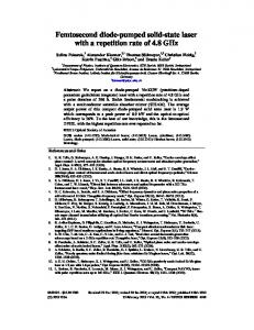
Fig. 1. rials.
Laser performance for high-gain ytterbium-doped mate-
that is another way for obtaining super-Gaussian modes. 2. Choice of Gain Medium
In a previous paper5 and using numerical simulations, we compared the performance achievable for pulse amplification in various ytterbium-doped crystals in terms of efficiency and extractable fluence. It was shown that, when high performance must be reached with diode pumping, a few numbers of known crystals may be used. These crystals are Sr5(PO4)3F) (S-FAP), Sr5(VO4)3F (S-FAV), Ca8La2 (PO4)6O2 (CLYPA), KY(WO4)2 (KYW), Sc2O3, and Y3Al5O12 (YAG). The corresponding optimum efficiency and extracted fluence are shown in Fig. 1. For these computations it was assumed that the crystals were pumped by two contrapropagating waves of 10᎑kW兾cm2 intensity. The parameters that were used for the computations appear in Table 1. The optimal length concentration product is that which leads to higher gain for a pump duration topt that leads to the best extraction efficiency. N is the number of passes trough the amplifier medium required for achieving complete depletion of the upper laser level when a 10᎑kW兾cm2, 10-ns FWHM pulse is injected. Last, is the thermal conductivity. Tungstates have efficiencies comparable to that of YAG, but the extractable fluence is lower. Sc2O3 has high melting temperature (2430 °C), and it does not appear possible to grow Table 1. Optimum Product of Amplifier Length and Yb Concentration 共LoptNYb兲 for a 15 kW/cm Pump Intensity, the Corresponding Optimum Pump Duration 共topt兲, the Number of Passes through the Amplifier Medium for Reaching Gain Saturation (N), and Thermal Conductivity () for High-Gain Yb-Doped Doped Crystals
Crystal Parameter
YAG KYW ScS2O3 CLYPA S-FAV S-FAP ⫺2
Lopt兾NYb共10 兾cm 兲 3.6 9.6 topt共ms兲 1.05 0.55 N 18 11 关共W/m兲兾K兴 13 3.3 20
1.96 1.00 13 15.5
0.84 0.6 14
0.69 0.32 7 1.7
0.83 0.50 6 2.0
large crystals. Thus the two candidates S-FAP and YAG allow high extracted fluence. Refer to Fig. 1; S-FAP undeniably provides the best performance in terms of efficiency. Nevertheless, S-FAP has a narrow absorption bandwidth, which is not compatible with high-power pulsed diode pumping. Indeed, its absorption bandwidth is only 3 nm, equal to the emission bandwidth of classic diodes. However, for high pumping power, several diodes that are not centered at the same wavelength are necessary. In addition, during the pump pulse and as a result of rising temperature, the emitted wavelength shifts (6 nm for 1-ms pulse duration for a bar emitting 100 W of power). Then the efficiency as computed in Ref. 5 vanishes and seems to be of the same order as that computed for YAG. An other property to be pointed out is absorption and emission cross-section anisotropy. These cross sections are high for S-FAP, and the results of Ref. 5 can be applied only if the pump and laser polarization follows the 具111典 axis. When light ducts are used for injecting the pump light, the polarization of the light emitted by the diodes is not maintained, and therefore the efficiency is reduced. Concerning the emission cross section, the anisotropy makes it impossible to use circular polarization that is capable of canceling spatial hole burning in the amplifiers and also reduces efficiency. We must also consider that, for high pump power, the thermal conductivity of S-FAP is six times lower and the quantum defect is two times larger than those of YAG, thus increasing the thermal loading of the amplifier medium. Then the prominent performance that can be achieved with S-FAP is the result of its high emission cross-section, which also makes efficient the transverse amplification of spontaneous emission, resulting in a large unwanted depletion of the upper laser level. Finally, the crystal growing technique does not make it possible to grow the large S-FAP crystals that are required for power amplifiers. Yb: YAG crystals can be grown in large sizes by the temperature gradient technique.17 With these considerations in mind, Yb:YAG seems to be a good candidate for a high average power oscillator and amplifier. However, as a result of its low emission cross section, which results in low gain and large saturation fluence, a large number of passes is necessary for extracting all the stored energy, and the pulse duration will be long for an oscillator with a cavity that is not too short. To increase the depletion of the upper-level population and the gain at every round trip, we assume that the beam performs two round trips in the amplifier medium at each cavity round trip, as described in Ref. 18 for a Nd:YAG laser. A schematic of such a resonator is shown in Fig. 2. This configuration is well suited to facilitate making dual-wavelength coatings when the angle between the pump and the laser beam is cos ⫽ p 兾 l. In our case, ⫽ 24°. 20 February 2005 兾 Vol. 44, No. 6 兾 APPLIED OPTICS
1019
Then the corresponding magnification of such a cavity reads as M ⫽ A ⫹ 冑A2 ⫺ 1,
Fig. 2. Schematic of the laser cavity: AR, antireflective; HR, highly reflective.
As a result of the four passes in the amplifier, we must be aware of the damage fluence of both the amplifier medium and the coating. The bulk damage threshold of Yb:YAG is ⬃100 J兾cm2 for nanosecond pulse widths.19 However, damage arises from defects such as absorption by impurities or surface defects that distort the wave front.20 In preliminary measurements, the surface damage threshold of an uncoated 1.6-mm-thick disk of 10-at. % doped Yb:YAG with 1-nm rms roughness was found to be 9 J兾cm2. These tests were performed with a 1.064᎑m Nd:YAG laser for which the absorption in 10-at. % Yb:YAG is 0.03 cm⫺1.21 For an identical sample from the same boule and the same polishing quality with conventional antireflection coating on both faces, it increases to 20 J兾cm2. For the megajoule laser that is being built in Bordeaux, France, a special coating of hafnia (hafnium oxide) was developed. A damage threshold as large as 100 J兾cm2 was obtained.22 Nevertheless, these results were validated with glass at low repetition rate. Tests are now planed with 0.05-nm rms roughness Yb:YAG substrates coated with Hafnia at 10 Hz. 3. Unstable Resonator with a super-Gaussian Gradient Reflectivity Output Mirror
Unstable cavities with super-Gaussian reflectivity output mirrors have been extensively studied.23–26 Here we recall briefly the main results of the previous analysis. Consider a cavity with length Lc made from two mirrors of radius of curvature Rci with i ⫽ o, m for the output and rear mirrors, respectively. We assume that the output mirror is coated with a superGaussian reflectivity of the form R ⫽ R0 exp关⫺2(r 兾 wm)n兴,
(1)
where wm is the 1兾e2 radius of the coating and n is the super-Gaussian mode order. The parameters gi that are usually used in the cavity read as
gi ⫽ 1 ⫺ 1020
L . Ri
(2)
APPLIED OPTICS 兾 Vol. 44, No. 6 兾 20 February 2005
A ⫽ 2g1g2 ⫺ 1,
⫽ ⫾1. (3)
If A2 ⬍ 1共⫺1 ⬍ A ⬍ 1兲, the magnification is imaginary with a module equal to 1 that corresponds to an oscillation of the beam in the cavity. If A2 ⬎ 1 共A ⬍ ⫺ 1, A ⬎ 1兲, it has been shown23 that such a cavity supports super-Gaussian eigenmodes of order n. Let us call wi and wr the beam waist size of the beam incident on and the beam reflected by the output mirror, respectively. The intensity distributions then read as Ii(r) ⫽ I0 exp关⫺2(r 兾 wi)n兴, Ir(r) ⫽ I0R0 exp关⫺2(r 兾 wr)n兴.
(4)
Simple calculations lead to wi ⫽ wm(Mn ⫺ 1)1兾n,
wr ⫽ wm共1 ⫺ M⫺n)1兾n, (5)
␥ ⫽ 1 ⫺ (R0 兾 M2),
(6)
where ␥ is the coupling loss of such a cavity generated by the output mirror. For a flat-topped mode, the condition R0Mn ⫽ 1
(7)
must be fulfilled. Taking into account relations (6 and (7), one fixes the cavity loss by magnification of the cavity. Nevertheless, this theory is valid only when the beams traveling back and forth in the cavity remain super-Gaussian and with the same order of superGaussian reflectivity. This is the case when the cavity length is short with respect to the Rayleigh range of the oscillating mode. However, during propagation, the shape of a super-Gaussian mode changes drastically and the wave front is distorted. Computations show that the mode exhibits a narrow peak intensity for a propagation distance close to the Rayleigh range. As a result of the diffraction induced by the high slope of the edges of a super-Gaussian mode, the Rayleigh range decreases when the mode order increases. This variation reads as
冋
ZR(n) ⫽ ZR(2)
8 ⌫(1 兾 2 ⫹ 2 兾 n)⌫(2 兾 n) ⌫(1 兾 2) n2
册
1兾2
,
(8)
where ZR共2兲 ⫽ 02兾 is the Rayleigh range of a Gaussian mode and ⌫ is the gamma function. Gain saturation can also distort the shape of the beams traveling inside the cavity, however.
4. Diffraction Computation
5. Amplification
According to Ref. 27 the diffraction integral may be expressed in term of the ABCD matrix elements. The expression for amplitude distribution A2共x2, y2兲 of the wave diffracted by a distribution A1共x2, y2兲 at distance L reads as
We shall now investigate the amplification of the beam in a diode-pumped ytterbium-doped material. First we assume that the amplifier is made from a thin sheet within which we neglect diffraction and that the incident pulse is short with respect to the upper-level lifetime. Let us call Xu, i the excited-state population density of the upper laser level and Fi the impinging laser fluence. The amplification of the pulse reads as5
A2(x2, y2) ⫽
冕冕
⫺ik exp ⫺ikL 2B
再
⫻ exp ⫺
A1(x1, y1)
ik A(x12 ⫹ y12) ⫺ 2(x1x2 ⫹ y1y2) 2B 关
冎
⫹ D(x22 ⫹ y22)兴 dx1dy1.
(9)
Fi⫹1 ⫽ Fi exp关g0L(Xu, i ⫺ fl)兴, with g0 ⫽ lNYb(flm ⫹ fun),
One may express Eq. (9) in radial coordinates by setting xi ⫽ i cos ,
yi ⫽ i sin ,
i ⫽ 1, 2.
In addition, an angular dependency is introduced, making it possible to simulate transverse-mode diffraction: A2(2, 2) ⫽
冉
冊
⫺ik D exp ⫺ik L ⫹ 2 2B 2B 2 ⫻
冕
r
⫽0
冏
⫻ exp ⫺ik
册
冋
A 2 k exp i cos(1 2B 1 B 1 2
⫺ 2) 1d 1d 1.
(10)
Integrating over 1, we get
冕
2
exp(i␣ cos )cos l d ⫽ 2i1J1(␣),
0
冕
2
exp(i␣ cos )sin l d ⫽ 0,
0
and then
冉
冊冏
⫺il⫺1 D 2 cos l 2 A2(2, 2) ⫽ exp ⫺ik L ⫹ 2B 2B 2 sin l 2 ⫻
冕
r
⫽0
冉
冊
flm , flm ⫹ fun
where flm and fun are the populations of sublevels m and n of the lower and upper levels, respectively, l is the emission cross section, and NYb is the ytterbium concentration. The upper-state population density must always be greater than fl for amplification to exist. After the beam is amplified, the new upperstate population density of the upper laser level reads as (13)
We assume a Yb:YAG disk pumped by a wave traveling forth and reflected back with an incident pump intensity equal to 15 kW/cm2. In a first step we compute the average value of the excited-state population density by using the numerical method described in Ref. 5. In a second step we compute the optimum length– concentration product for various pump pulse durations. Using the optimum length and the corresponding pump pulse duration, we compute the corresponding efficiency for an amplifier. We can observe that the ratio of efficiency to pump pulse duration reaches a maximum value that we call the optimum pump pulse duration. In our case, the optimum pulse duration is 1 ms and the corresponding optimum length– concentration product is 2 ⫻ 1020. Then, for an ytterbium concentration of 6 ⫻ 1020, the optimum length is 1.6 mm, the g0l product is 4.65, and the average population density of the upper laser level is 0.205. With these parameters, an amount of pump energy is transmitted. The pump beam transmission is Tp ⫽ 0.11. 6. General Method of Numerical Computation
In the numerical computations made here, we restrict the analysis to a confocal cavity for which
A1(1)exp ⫺ik
A 2 k ⫻ J d 1d 1. 2B 1 l B 1 2 1
fl ⫽
Xu, i⫹1 ⫽ fl ⫹ (Xu, i ⫺ fl)exp(⫺Fi)
cos l 1 A1(1) sin l 1
(12)
Rcm ⫽ 2Lc ⫺ Rco.
(11)
This makes it possible to reduce the two-dimensional integral to only one dimension.
Then M ⫽ 1 ⫺ 2(Lc 兾 Rco). 20 February 2005 兾 Vol. 44, No. 6 兾 APPLIED OPTICS
1021
Fig. 3. Variation of power output (curve A) and parameter (curve B) relative to number of round trips for ␥ ⫽ 0.8 and n ⫽ 4.
The numerical computations are performed as follows: Starting from a random distribution of both amplitude and phase on the rear mirror, this distribution is propagated by use of Eq. (11) up to the output mirror. Then we compute the phase and the amplitude of the reflected wave, using the radius of curvature and the reflectivity distribution of the output mirror, and the resultant wave is propagated to the rear mirror. We then compute the new reflected wave, using the characteristics of the rear mirror and the amplification by the amplifier medium, and continue until the gain is totally depleted. To take into account the transmission of the optical elements in the cavity (Pockels cell, polarizer, quarter-wave plate) we assume a 5% loss at every round trip located on the rear mirror. To characterize the mode stability, we define a parameter such that ⫽
Iout(wm 兾 2) . Iout(wm)
(15)
Figure 3 shows the output power (curve A, left-hand scale) and parameter (curve B, right-hand scale) relative to the number of round trips. The parameters chosen for these computations are listed in Table 2. The coupling loss for this case is 80%. After a few round trips the mode stabilizes, and its shape remains stable until the saturation takes place. During this period the logarithm of the output power grows linearly, showing that no saturation occurs. The beam propagates in a linear medium, and the incident and reflected mode sizes are given by Eqs. (5). When the excited-state denTable 2.
sity is locally depleted, depending on the mode shape generated by the former period the mode shape changes. After a few round trips the gain is uniformly depleted and a new linear process takes place. The logarithm of the output power decreases linearly relative to the number of round trips, which corresponds to the loss induced by the cavity, as the gain reservoir is empty. The new mode shape is slightly different from that which corresponds to the first period. In Fig. 4 are plotted the mode shapes and the radial distribution of the remaining upper-level population density normalized to the initial density before saturation occurs 共N ⫽ 62兲, at the maximum of the output power 共N ⫽ 68兲, and when the amplifier is saturated 共N ⫽ 80兲. The limit value of this ratio equal to fl兾Xu0 for which the crystal is transparent to the laser wave is also plotted. For N ⬎ 68 the available gain does not compensate for the cavity losses, and the intensity inside the cavity vanishes. For N ⬎ 80, as the intensity is low, no depletion
Pump and Cavity Parameters Used for the Computations
Pump Ip0 ⫽ 15 kW/cm2 Radius of curvature Rco ⫽ ⫺ 3.25 m Rcm Cavity characteristics Lc ⫽ 0.5 m M Mirror reflectivity R0 ⫽ 0.34 Rmax Super-Gaussian parameters wm ⫽ 2.5 mm n
1022
Fig. 4. Change of the mode profile (circles) and of the upper-state population density normalized to the initial population density (squares) for number of round trips N equal to 62 (end of the linear propagation in an unsaturated gain medium), 68 (maximum output power), and 80 (beginning of the linear propagation in a totally saturated gain medium) versus radius for ␥ ⫽ 0.8 and n ⫽ 4.
⫽ ⫽ ⫽ ⫽ ⫽
1 ms 4.25 m 1.31 0.95 4
APPLIED OPTICS 兾 Vol. 44, No. 6 兾 20 February 2005
Fig. 5. Output mode averaged on all pulse durations (curve A), the corresponding internal intensity on the output mirror (curve B), and the mirror reflectivity distribution (curve C) versus radius for ␥ ⫽ 0.8 and n ⫽ 4.
high intensity several round trips before. Then, it depletes the upper state population, preventing transverse-mode oscillation. Finally, we simulate the focusing of the output beam by a lens located on the output mirror. For this computation we first compute the distance for which the intensity of the focused beam on the axis is maximum. Then we compute the intensity distribution in this plane. We find that the shape of the focused beam and the focusing distance change slightly during saturation. In Fig. 7 are shown the variations of focusing distance Zed when a lens of 4-m focal length is used and of the fraction of energy in the main diffraction lobe, Frac. Fig. 6. Evolution of the fundamental 共L ⫽ 0兲 and the first-order 共L ⫽ 1兲 transverse modes versus the number of round trips for ␥ ⫽ 0.8 and n ⫽ 4.
of the upper-level population occurs; from N ⫽ 80 to N ⫽ 400, it is reduced by only 3 ⫻ 10⫺6. The average intensity over all the round trips for the output beam and the total intensity inside the cavity on the output mirror have also been computed. The results are shown in Fig. 5, where curve C is the mirror’s reflectivity. Curve A is the output beam, and curve B is the total intensity of the beams propagating back and forth inside the cavity on the output mirror. This curve exhibits a super-Gaussian shape with the same waist size as curve A but with a 3.7 super-Gaussian mode order. We then compute the energy inside the cavity, and, using the equivalent area of a superGaussian mode given by S(n) ⫽ 22⫺2兾n
⌫(2 兾 n) S(2), n
02 S(2) ⫽ , 2
(16)
7. Cavity Optimization
Several computations have been made for various sizes wm and various super-Gaussian mode orders n. To make the results comparable, we set coupling loss ␥ to be constant. Referring to Fig. 5, we can see, however, that, although the magnification of the cavity M and the output mirror reflectivity at center R0 verify relation (7), the top of the mode is not plane because of saturation. Then we analyze the results obtained for various values of K, such as K ⫽ MnR0. Then the loss reads as
Eout , Ppumpp
Ppump ⫽ p2Ip0.
(17)
The results appear in Table 3, where l is the FWHM of the laser pulse. In Fig. 6 is plotted the output power versus the number of round trips for both the fundamental and the first-order transverse modes. Resulting from the losses undergone by the last one, the first one reaches Table 3.
Ppump 9.6 kW wout共1兾e2兲 3.5 mm
Results Obtained with the Parameters of Table 2
Eout 1.3 J
13.7%
Fint 8.9 J/cm2
wint共1兾e2兲 3.3 mm
wp 共10⫺3兲 4.5 mm
l 12.7 ns
K
␥⫽1⫺
Mn⫹2
.
(19)
With a given value of ␥, the corresponding values of magnification M, reflectivity R0 at the center of the output mirror, and radii of curvature Rco and Rcm are given by
which increases when n increases, we can compute the maximum fluence inside the cavity. Let us call wp the radius of the beam inside the cavity for which Iint共wp兲 ⫽ Iinf共0兲 ⫻ 10⫺3. We assume now that the amplifier medium is pumped over this diameter, and we deduce the efficiency: ⫽
(18)
A.
M⫽
冉 冊
Rco ⫽
2Lc , 1⫺M
K 1⫺␥
1兾n⫹2
,
R0 ⫽
Rcm ⫽ ⫺
K Mn
,
2MLc . 1⫺M
Effects of Coupling Loss
In a first step we investigate the effects of the coupling loss. In Fig. 8(a) the efficiency versus ␥ for is given n ⫽ 4 and K ⫽ 1. High efficiency may be reached with low coupling loss. Figure 8(b) shows the number of round trips necessary for reaching the maximum output power and the corresponding pulse duration. For few coupling losses, as all the available stored energy is consumed in fewer round trips than for more coupling losses, the efficiency is greater. In addition, the magnification is low, the beam inside the cavity is quasi-Gaussian and remains confined on the axis of the cavity, and the reflectivity at the center of the coupling mirror is high. Then the fluence inside the cavity grows drastically. The mode is unstable, with poor transverse mode selectivity and, when we plot a graph similar to the one shown in Fig. 6, the 20 February 2005 兾 Vol. 44, No. 6 兾 APPLIED OPTICS
1023
Fig. 7. Evolution of focusing distance 共Zed兲 and fraction of energy in the main lobe 共Frac兲 versus the number of round trips for ␥ ⫽ 0.8 and n ⫽ 4.
curves that correspond to L ⫽ 0 and L ⫽ 1 overlap, with high intensity making mode competition possible. In Fig. 8(c) the extracted energy (left-hand scale) and the internal fluence (right-hand scale) are plotted versus ␥. We then choose a coupling loss equal to 80% to get an internal fluence lower than 10 J/cm2 and efficient mode discrimination. B.
Effect of Mode Order
For the same values of Ip0共15 kW/cm2兲, 共1 ms兲, wm 共2.5 mm兲, Rmax共0.95兲, ␥ ⫽ 0.8, K ⫽ 1, and Lc ⫽ 共0.5 m兲, we now compute the performance of the laser versus the mode order. The values of the cavity parameters that correspond to the values of n are given in Table 4. Figure 9(a) presents the results for extracted energy (left-hand scale) and internal fluence (righthand scale). When a super-Gaussian mode propagates, its intensity distribution does not remain super-Gaussian, and its wave front is not spherical. Then, after a round trip in a cavity with spherical mirrors, the mode undergoes losses. As the Rayleigh range decreases when n increases [Section 2, Eq. (8)], the losses increase with n. This behavior may be prevented by use of graded phase mirrors. In addition, diffraction losses are larger when n increases. As a result, Eout decreases. Nevertheless, as the pumped area decreases when n increases, the efficiency increases as shown in Fig. 9(b). However, for n ⬎ 5, the mode begins to be unstable and never stabilizes. When the computation is made several times starting from different random amplitude and phase distributions, the instantaneous mode shapes are not the same, though the average mode shape remains identical to itself at each round trip. For n ⬍ 5 the mode shape remains identical and the number of round trips that corresponds to the maximum power output changes within a ⫾2 margin of error. For n ⫽ 4, the values of from N ⫽ 25 to N ⫽ 60 on the one hand and from N ⫽ 78 and N ⫽ 100 on the other hand agree within 10⫺6. Finally, we investigate the effect of n on the fraction of the output energy contained in the main dif1024
APPLIED OPTICS 兾 Vol. 44, No. 6 兾 20 February 2005
Fig. 8. (a) Efficiency versus coupling loss ␥ for n ⫽ 4 and K ⫽ 1. (b) Number of round trips necessary to reach maximum output power N and FWHM pulse duration versus coupling loss ␥ for n ⫽ 4 and K ⫽ 1. (c) Output energy 共Eout兲 and maximum internal fluence 共Fint兲 versus coupling loss ␥ for n ⫽ 4 and K ⫽ 1.
fraction lobe. Figure 9(c) shows the variations of Zed and Frac against n. When n increases, the wave front becomes convex and, consequently, Zed increases. In addition, the value of Frac reaches an optimum for n ⫽ 4.
Table 4. Cavity Parameters versus Mode Order for Lc ⫽ 0.5 m, ␥ ⫽ 0.8 and K ⫽ 1
n
M
R0
Rcm 共m兲
Rco 共m兲
2 3 4 5 6 8
1.50 1.38 1.31 1.26 1.22 1.17
0.45 0.38 0.34 0.32 0.30 0.28
3.02 3.63 4.25 4.87 5.49 6.73
⫺2.02 ⫺2.63 ⫺3.25 ⫺3.87 ⫺4.49 ⫺5.73
C. Effect of K
We now analyze the effect of K on performance when ␥ ⫽ 80% and n ⫽ 4. Figure 10(a) shows the extracted energy (left-hand scale) and the efficiency and the internal fluence (right-hand scale) versus K. As the efficiency and the internal fluence seem to be roughly constant, the energy increases. Considering the variations of Frac compared with K shown in Fig. 10(b), however, we cannot see a significant variation, and we then conclude that a value of K ⫽ 1.2 seems to allow for a high energy level with high efficiency, high transverse mode discrimination, and an internal fluence less than 10 J/cm2. For K ⫽ 1.2 the magnification is 1.35 and the corresponding mirror parameters are Rco ⫽ ⫺2.87 m, Rcm ⫽ 3.87 m and R0 ⫽ 0.36. As the mode is larger, the output energy is 1.4 J. However, the pump power is also larger, and the efficiency is unchanged. As Ref. 28 indicates, great attention must be given to the coating reflectivity of the amplifier faces at pump wavelength. If the residual reflectivity of the input face increases the stored pump energy for resonant monochromatic pumping when the spectral width of the pump is large compared with the free spectral range of the Fabry–Perot interferometer, the pump light for which the wavelength lies between two resonances is partially rejected. In Fig. 11 the amount of the pump energy stored in the cavity is shown relative to Rp0 for various values of Rpm, assuming that Tp ⫽ 0.11, as corresponds to our case. 8. Comparison of an Unstable Cavity with super-Gaussian Mirror Reflectivity and a Stable Cavity with Graded Phase Mirror
We now compare the technique that uses an unstable cavity with a super-Gaussian reflectivity mirror with that which consisting uses a stable cavity with a graded phase mirror. This graded phase mirror also makes it possible to generate a super-Gaussian mode shape. This technique has already been studied.28 –36 In this technique the profile of one of the cavity mirrors is identical to the wave front given by a superGaussian mode after it has traveled through the cavity. Then the reflected wave front is the phase conjugate of the incident wave front, and the superGaussian mode for which the mirror is designed is the eighth mode of the cavity. It has been shown that, as in conventional cavities, mode discrimination is efficient when the cavity length is equal to or of the same order
Fig. 9. (a) Output energy 共Eout兲 and total maximum internal fluence 共Fint兲 versus mode order n for coupling loss ␥ ⫽ 0.8 and K ⫽ 1. (b) Efficiency versus mode order n for ␥ ⫽ 0.8 and K ⫽ 1. (c) Evolution of focusing distance 共Zed兲 and fraction of energy in the main lobe 共Frac兲 for the maximum output power versus mode order n for ␥ ⫽ 0.8 and K ⫽ 1.
as the Rayleigh range of the super-Gaussian mode. Indeed, for a cavity length shorter than the Rayleigh range, no diffraction occurs, the wave front remains plane, and thus mode selection is impossible. Compared with the former method, for which diffraction must be negligible, in this technique it must be large to furnish the graded phase mirror the deep modulation 20 February 2005 兾 Vol. 44, No. 6 兾 APPLIED OPTICS
1025
Fig. 12. Peak intensity of a propagated super-Gaussian mode of order 20 normalized to the intensity of the mode at the center versus propagation distance normalized to the Rayleigh range.
Fig. 10. (a) Variation of (top to bottom) efficiency, extracted energy, and maximum internal fluence versus parameter K for ␥ ⫽ 0.8 and n ⫽ 4. (b) Variation of focusing distance 共Zed兲 and fraction of energy in the main lobe 共Frac兲 versus K parameter for ␥ ⫽ 0.8 and n ⫽ 4.
that will make possible the imposition of the corresponding mode. With regard to Eq. (10), the Rayleigh ranges of the super-Gaussian modes are shorter than those for Gaussian modes as a result of diffraction by
the edges of the mode. Nevertheless, when a large mode size is wished, the cavity length must be long. For example, for w0 ⫽ 3.5 mm and ⫽ 1 m, ZR ⫽ 38.5 m, leading to long pulses. Because of the high slope edges, the mode is largely diffracted, and for limited mirror sizes strong spatial-frequency filtering occurs and deep modulations are set on the flat top. In addition, the intensity distribution of a superGaussian mode changes during propagation, and for high values of n the peak intensity is maximum at the Rayleigh range. Figure 12 shows the peak intensities of super-Gaussian modes of order 20 versus the ratio of the propagation distance to the Rayleigh range; for high values of n and at a distance close to the Rayleigh range, the peak intensity is large and the graded phase mirror may be damaged. We then conclude that an unstable resonator with a superGaussian reflectivity mirror seems to be well suited for laser application, as the cavity length is short and the output mode shape is smooth. Cavities with graded phase mirrors seem to be good choices for regenerative amplifiers for which the cavity must be lossless.37 9. Conclusions
Fig. 11. Intensity stored in a slab of the amplifier medium in the schematic shown in Fig. 2 versus reflectivity of the input face for various reflectivities R of the rear face. 1026
APPLIED OPTICS 兾 Vol. 44, No. 6 兾 20 February 2005
We have presented numerical results for the optimization of a longitudinally diode pumped Yb:YAG amplifier in an unstable confocal cavity with a superGaussian reflectivity output coupler. We have described the method used. Taking into account the laser parameters of Yb:YAG, we found that the coupling loss must be large to prevent high fluence inside the cavity. Restricting our investigations to the case in which the top of the output mode is flat 共K ⬇ 1兲, we found that low coupling loss leads to a large radius of curvature of the mirror with high output coupler reflectivity. These factors are favorable for transverse mode oscillation and lead to high influence inside the cavity. With high coupling loss, high transverse-mode discrimination with good performance in terms of extracted energy, efficiency, and focusing may be found in the nanosecond regime for a mode order equal to 4.
Experimental validation of these results is now in progress.
References 1. L. D. DeLoach, S. A. Payne, L. L. Chase, L. K. Smith, W. L. Kway, and W. F. Krupke, “Evaluation of absorption and emission properties of Yb3⫹ doped crystals for laser applications,” IEEE J. Quantum Electron. 29, 1179 –1191 (1993). 2. A. Brenier and G. Boulon, “Overview of the best Yb3⫹-doped laser crystals,” J. Alloys Compd. 323-324, 210 –213 (2001). 3. A. Brenier, “A new evaluation of Yb3⫹-doped crystals for laser application,” J. Lumin. 92, 199 –204 (2001). 4. G. L. Bourdet, “New evaluation of ytterbium doped materials for cw lasers applications,” Opt. Commun. 198, 411– 417 (2001). 5. G. L. Bourdet, “Comparison of pulse amplification performances in longitudinally pumped ytterbium doped materials,” Opt. Commun. 200, 331–342 (2001). 6. R. J. Beach, E. C. Honea, S. B. Sutton, C. M. Bibeau, J. A. Skidmore, M. A. Emanuel, S. A. Payne, P. V. Avizonis, R. S. Monroe, and D. G. Harris, “High-average-power diode-pumped Yb:YAG lasers,” in Advanced High-Power Lasers, M. Osinski, H. T. Powell, and K. Toyoda, eds., Proc. SPIE 3889, 246 –260 (2000). 7. C. Stewen, K. Contag, M. Larionov, A. Giesen, and H. Hügel, “A 1 kW cw thin disc laser,” IEEE J. Sel. Top. Quantum Electron. 6, 650 – 657 (2000). 8. C. Bibeau, “The Mercury project—a gas cooled, 10 Hz, diode pumped Yb:S-FAP system for inertial fusion energy,” presented at the EPS-QEOD Europhoton Conference, Lausanne, Switzerland, 29 August–3 September, 2004. 9. J. Hein, S. Podleska, M. Siebold, M. Hellwing, R. Bödefeld, R. Sauerbrey, D. Ehrt, and W. Wintzer, “Diode-pumped chirped pulse amplification to the joule level,” Appl. Phys. B 79, 419 – 422 (2004). 10. G. L. Bourdet, J.-C. Chanteloup, A. Fülöp, Y. Julien, and A. Migus, “The LUCIA project: a high average power ytterbium diode pumped solid state laser chain,” in Laser Optics 2003: Solid State Lasers and Nonlinear Frequency Conversion, V. I. Ustugov, ed., Proc. SPIE 5478, 4 –7 (2003). 11. E. Innerhofer, T. Südmeyer, F. Brunner, R. Häring, A. Aschwanden, R. Paschotta, C. Hönninger, M. Kumkar, and U. Keller, “60-W average power in 810-fs from a thin-disk YB: YAG laser,” Opt. Lett. 28, 367–369 (2003). 12. F. Druon, S. Chenais, P. Raybaut, F. Balembois, P. Georges, R. Gaumé, G. Aka, B. Viana, S. Mohr, and D. Kopf, “Diodepumped Yb:Sr3Y(BO3)3 femtosecond laser,” Opt. Lett. 27, 197–199 (2002). 13. V. V. Ter-Mikirtychev and V. A. Fromzel, “Directly singlediode-pumped continuous-wave Yb3⫹:YAG laser tunable in the 1047–1051-nm wavelength range,” Appl. Opt. 39, 4964 – 4969 (2000). 14. F. Druon, F. Augé, F. Balembois, P. Georges, A. Brun, A. Aron, F. Mougel, G. Aka, and D. Vivien, “Efficient, tunable, zero-line diode-pumped continuous-wave Yb3⫹:CaLnO共BO3兲3 共Ln ⫽ Gd, Y兲 lasers at room temperature and application to miniature lasers,” J. Opt. Soc. Am. B 17, 18 –22 (2000). 15. Y. Zhou, Q. Thai, Y. C. Chen, and S. Zhou, “Monolithic Q-switched Cr, Yb:YAG laser,” Opt. Commun. 219, 365–367 (2003). 16. E. C. Honea, R. J. Beach, S. C. Mitchell, J. A. Skidmore, M. A. Emanuel, S. B. Sutton, S. A. Payne, P. V. Avizonis, R. S. Monroe, and D. G. Harris, “High-power dual-road Yb:YAG laser,” Opt. Lett. 25, 805– 807 (2000).
17. G. Zhao, J. Si, X. Xu, J. Xu, H. Song, and Y. Zhou, “Growth of large-sized Yb:YAG single crystals by temperature gradient technique,” J. Cryst. Growth 252, 355–359 (2003). 18. U. Brauch, A. Giesen, M. Karszewski, C. Stewen, and A. Voss, “Multiwatt diode pumped Yb:YAG thin disk laser continuously tunable between 1018 and 1053 nm,” Opt. Lett. 20, 713–715 (1995). 19. J.-F. Bisson, Y. F. A. Shirakawa, H. Yoneda, J. Lu, H. Yagi, T. Yanagitani, and K.-I. Ueda, “Laser damage threshold of ceramic YAG,” Jpn. J. Appl. Phys. Part 2 42,L1025–L1027 (2003). 20. J.-Y. Natoli, L. Gallais, H. Akhouayri, and C. Amra, “Laserinduced damage of materials in bulk, thin-film, and liquid forms,” Appl. Opt. 41, 3156 –3166 (2002). 21. Zhiwei Zhao, Shanghai Institute of Optics and Fine Mechanics, Shanghai, China (personal communication, 2004). 22. B. Pinot, H. Leplan, F. Houbre, E. Lavastre, J. C. Poncetta, and G. Chabassier, “Laser megajoule 1.06 m mirror production with very high laser damage threshold,” in Laser-Induced Damage in Optical Materials: 2001, G. J. Exarhos, A. H. Guenther, K. L. Lewis, M. J. Soileau, and C. J. Stolz, eds., Proc. SPIE 4679, 234 –241 (2001). 23. A. G. Siegman, “Unstable optical resonator for laser applications,” Proc. IEEE 53, 277–287 (1965). 24. A. G. Vakhimov, “Open resonators with mirror having variable reflexion coefficients,” Radio Eng. Electron. Phys. 10, 1439 – 1446 (1965). 25. M. Couture and M. Piché, “Resonator with variable-reflectivity output coupler,” Appl. Opt. 23, 2510 –2513 (1987). 26. S. de Silvestri, P. Laporta, V. Magni, and O. Svelto, “Solidstate laser unstable resonators with tapered reflectivity mirrors: the super-Gaussian approach,” IEEE J. Quantum Electron. 24, 1172–1177 (1988). 27. S. A. Collins, Jr., “Lens-system diffraction integral written in terms of matrix optics,” J. Opt. Soc. Am. A 60, 1168 –1177 (1970). 28. G. L. Bourdet and R. A. Muller, “Tm, Ho:YLF microchip laser under Ti:sapphire and diode pumping,” Appl. Phys. B 70, 345– 349 (2000). 29. P. A. Bélanger and C. Paré, “Optical resonators using gradedphase mirrors,” Opt. Lett. 16, 1057–1059 (1991). 30. C. Paré and P. A. Bélanger, “Custom laser resonators using graded-phase mirrors,” IEEE J. Quantum Electron. 28, 355– 362 (1992). 31. C. Paré and P. A. Bélanger, “Custom laser resonators using graded-phase mirrors: circular geometry,” IEEE J. Quantum Electron. 30, 1141–1148 (1994). 32. P. A. Bélanger, R. Lachance, and C. Paré, “Super-Gaussian output from a CO2 laser by using a graded-phase mirror resonator,” Opt. Lett. 17, 739 –741 (1992). 33. R. Van Neste, C. Paré, R. L. Lachance, and P. A. Bélanger, “Graded-phase resonator with a super-Gaussian output in a cw CO2 laser,” IEEE J. Quantum Electron. 30, 2663–2699 (1994). 34. J. R. Leger and G. Mowry, “External diode laser array cavity with mode-selecting mirror,” Appl. Phys. Lett. 63, 2884 –2886 (1993). 35. J. R. Leger, D. Chen, and Z. Wang, “Diffractive optical element for mode shaping of a ND:YAG laser,” Opt. Lett. 19, 108 –110 (1994). 36. G. L. Bourdet and M. Mérian, “Theoretical investigation of a slab CO2 laser resonator with graded-phase mirror,” Opt. Commun. 152, 49 –54 (1998). 37. V. Bagnoud, J. Luce, L. Videau, and C. Rouyer, “Diode-pumped regenerative amplifier delivering 100 mJ single mode laser pulses,” Opt. Lett. 26, 337–339 (2001).
20 February 2005 兾 Vol. 44, No. 6 兾 APPLIED OPTICS
1027