... SMPLE algorithm; and temperature was got by solving energy equation. Third, add a time step. Don't stop repeating this process until the filling process finish.
Available online at www.sciencedirect.com
Energy Procedia 17 (2012) 1864 – 1871
2012 International Conference on Future Electrical Power and Energy Systems
Numerical Simulation of Casting Filling Process Based on FLUENT YUWEN Xuan-xuan1,2ˈ CHEN Ling1,2ˈHAN Yi-jie3 1. (Tianjin Key Laboratory for Control Theory & Applications in Complicated Systems, Tianjin University of Technology, Tianjin 300384, China) 2. (School of Mechanical Engineering, Tianjin University of Technology, Tianjin 300384, China) 3.˄School of Foreign LanguagesˈRenmin University of ChinaˈBeijing100872ˈChina˅
Abstract Based on finite element theory, using FLUENT software and three-dimensional model to simulate liquid metal free surface and temperature field of casting filling process numerically. Boundary and initial conditions, such as velocity, pressure, temperature, etc., was reasonably set. The feasibility of using FLUENT to simulate three-dimensional casting was studied; the fluctuation of molten metal free surface was observed; the temperature distribution data on the end of filling was recorded, for further numerical simulation of casting solidification process which provided an accurate initial condition. This paper also predicted defects on casting filling process, and provided a basis for process optimization. and/or peer-review under responsibility of [name organizer] © 2011 2012 Published Publishedby byElsevier ElsevierLtd. Ltd.Selection Selection and/or peer-review under responsibility of Hainan University. Open access under CC BY-NC-ND license. Keyword: Mold Filling Simulation; FLUENT; Free Surface; Temperature Field
Casting filling process plays an important role in casting production process. Many casting defects, such as blowhole, slag inclusion, shrinkage, cold shut and so on, are related to filling process. The process that high-quality castings are obtained by controlling the order of filling and flow patterns is quite necessary. The filling process is the first stage of molding process, as well as the most complicated process, because many subjects, including computational fluid dynamics (CFD), heat transfer, numerical methods, computer graphics, partial differential equations and so on were involved. Therefore, the numerical simulation of filling process is very difficult, filling simulation is still one of the hot areas of casting numerical simulation [1]. 1. Selection of simulation software Numerical simulation of casting process takes a leading place in casting subject; and it is a branch of
1876-6102 © 2012 Published by Elsevier Ltd. Selection and/or peer-review under responsibility of Hainan University. Open access under CC BY-NC-ND license. doi:10.1016/j.egypro.2012.02.324
1865
YUWEN Xuan-xuan et al. / Energy Procedia 17 (2012) 1864 – 1871
science using computer technology to transform and update traditional casting technology. With the rapid development of computer science and technology, many kinds of finite element software have being sprung up all over the world, including both casting professional software and large general finite element analysis software. Up to now, numerical computation of flow field and temperature field have been mainly implemented by casting professional software, such as Germany’s MAGMA, the United States’ s PROCAST and FLOW3D, Tsinghua University’s FT-STAR, etc. However, most casting professional software is expensive with unmulti-functions, which cannot meet the needs of most manufacturers and institutes, for the reason that they make not only cast, but also mechanical design and manufacture. Therefore, purchasing and using common finite element analysis software is an ideal choice for many institutes and manufactures. With the improvement of commercial software, some large-scale engineering-oriented general finite element(FE) software constantly derive latest numerical computation methods and computer technology. The general FE software is more accurate than professional software. What’s more, the analysis results of general software are reliable. Therefore, general software that will help numerical simulation used for simulating casting process is applied widely in the foundry industry [2]. Currently, America’s large general-purpose finite element analysis software ANSYS is used most widely in China. As FLUENT and CFX finite element software companies had been purchased by ANSYS company, ANSYS software is becoming more and more powerful in the field of calculation of three-dimensional flow. This makes the simulation of free surface of liquid metal in three-dimensional case more effectively by FLUENT calculation module. FLUENT calculation module is part of ANSYS software. This paper uses FLUENT solver to numerical simulate flow field and temperature field of casting filling process with free surface for three-dimensional model. 2 The basic theory of filling numerical simulation 2.1 Mathematical Model of Numerical Simulation [3][4][5] Casting filling process belongs to unsteady flow of incompressible viscous liquid with free surface. The simulation can be regarded as solving the change of flow, temperature and free surface of liquid metal in filling process. This process can be described by continuity equation (mass conservation equation), momentum conservation equation, energy equation and volume of fluid-function equation. A. Continuity equation (mass conservation equation): wv ww wu (1) 0 D � � wz wy wx Where D is divergence; u, v, w are components of velocity vector in x, y, z direction, m/s; B. N-S equation (momentum conservation equation): ½ wu wu wu wu wp U( ) � �u �v �w � Ug x � P 2u ° wt wx wy wz wx ° (2) ° wp wv wv wv wv 2 U( ) � � Ug y � P v ¾ �w �v �u wy wz wy wx wt ° ° wp ww ww ww ww 2 U( ) � � Ug z � P w ° �w �v �u wz wz wy wx wt ¿ Where p is pressure of unit density, Pa; P is dynamic viscosity, Pas; g is acceleration of gravity, m/s2; 2 is laplacian; U is density of fluid; t is filling time, s. C. Energy equation: wT wT w wT w wT wT wT w wT (3) Uc � U cu � U cv � U cw (k ) � (k ) � (k ) � S wt
wx
wy
wz
wx
wx
wy
wy
wz
wz
1866
YUWEN Xuan-xuan et al. / Energy Procedia 17 (2012) 1864 – 1871
Where c is specific heat capacity, J·(kg·k)-1; S is heat which resulting from the liquid surface stress applying work for liquid, J; T is temperature of liquid, K; k is thermal conductivity of liquid, w·(m·k)-1. In the form of eq.(3), items 2,3,4 on the left of equal-sign are the temperatureshift which was caused by fluid flow, The formula shows that the heat conduction process is consisted of two parts. One part is heat conduction of the fluid itself. The other part depends on macro-displacement of fluid. D. Volume of fluid-function equation: VOF method is adopted to simulate free surface. A volume function F need to be defined when computational domain is determined. The state of each grid can be expressed by F value. F is defined as follows: OV (4) F AV Where OV is the volume of fluid in one grid, m3; AV is the volume of one grid, m3. The value is unity for cells fully occupied by fluid, zero for empty cells, and between 0 and 1 for surface cells. While the volume of fluid-function equation need to be solved: wF wF wF wF (5) �u �v � w 0 wt wx wy wz Where u, v, w are components of velocity vector in x, y, z direction of grid point(x, y, z), m/s;
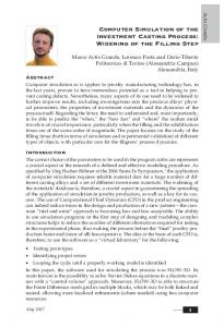
2.2 Flow of Numerical Calculation In this paper, first of all, the location of the free surface of liquid metal was tracked by solving the volume of fluid-function equation, determining computational domain of current time. Second, flow field and temperature field were simulated by using SMPLE algorithm; and temperature was got by solving energy equation. Third, add a time step. Don’t stop repeating this process until the filling process finish. Specific process is illustrated in Fig.1.
Fig.1 Flow of Calculation
YUWEN Xuan-xuan et al. / Energy Procedia 17 (2012) 1864 – 1871
3 Geometric model and technological parameter
3.1 Geometric and Finite Element Model Through calculation repeatedly, it is find that the characteristics of the way of anti-gravity bottom pouring are high speed of calculation, easy convergence and good continuity of free surface in numerical simulation. Meanwhile, the way of anti-gravity bottom pouring has the following characteristics, which are liquid metal flowing more smoothly, little probability of appearing blowhole, and slag inclusion in actual production [7]. According to the sample of actual production, the model of cell body with bottom pouring channel was used in this paper. The specific dimension of model is shown in Fig.2. Unit is millimeter.
Fig.2 Model Size
Meshing is the core of building finite element model. To a great extent, the rationality of the model depends on the grid. The convergence of computing, calculation scale and precision are directly affected by many key factors of grid, such as quantity, density, quality, layout, the coordination of displacement and so on. The cell body model of 3D which is build by PRO/E software was meshed by ICEM meshing tool which includes in ANSYS software. Through having meshed and piloted calculation for many times, considering the quality of the model, calculation speed and precision, grid with 20364 nodes and 114764 tetrahedral elements were finalized shown in Fig.3.
Fig.3 Effect of Grid
3.2 Technological Parameter In this paper, the material of casting is pure aluminum. The performance parameters are shown in Tab.1:
1867
1868
YUWEN Xuan-xuan et al. / Energy Procedia 17 (2012) 1864 – 1871
Tab.1 performance parameters of casting
Density
Thermal Conductivity
kg/m3
W·(m·k)-1
2300
100
Heat Capacity
Crystallization
J·(kg·k)-1
Heat
J·kg-1
1090
Solidus o
394000
Liquidus o
C
635
Dynamic Viscosity
C
N·s·m-2
660
0.001
3
The material of mold is hot die steel 3Cr2W8V. Density: U =2710 kg/m . The Thermo-physical performance parameters of casting mould material are shown in Tab.2: Tab.2 Thermo-physical Performance Parameters of Casting Mould Temperature Thermal Conductivity Heat Capacity
o
C
100
200
300
500
700
W·(m·k)-1
20.1
20.2
22.7
23.4
24.3
J·(kg·k)-1
468.2
525.5
56.4
612.3
685.5
o
o
In simulation process, pouring temperature is 700 C; ambient temperature is 25 C; pouring rate is 0.2m/s, using the way of anti-gravity bottom pouring; acceleration of gravity is 9.8m/s2. 4 Simulation and results
In this simulation of casting filling process, multiphase flow(VOF), energy, turbulence and solidification options were chosen. Also, reasonable numerical simulation formula was chosen. Liquid surface tension was controlled. Casting, mold material properties and calculation boundary conditions were applied. The whole calculation domain state was initialized. Flow field and temperature field were coupling simulated. The time of 3D model of cell body finished filling process consisting with actual production of filling were obtained after using FLUENT simulation. 4.1 Free Surface of Filling Process In the whole simulation of casting filling process, the flow of molten metal can be divided into five parts. (1) Liquid metal enters from gate entrance. Liquid surface rises steadily in the gate. Liquid metal fills the whole gate at 0.29 seconds, as illustrated in (a) of Fig. 4 (2) Liquid metal begins to flow smoothly into the bottom of die cavity from center after 0.29 seconds, as illustrated in (b) of Fig. 4. When liquid metal flows in the die cavity, it firstly contacts with c, d wall of tank. At the same time, it flows to a, b wall of tank, as illustrated in (c) of Fig. 4. When the flow of liquid metal along the wall firstly reaches a, b wall, liquid metal begins to flow back to the middle part of the die cavity from the wall of tank; and then, it intersects with middle of the liquid. (3) The bottom of the cavity will be filled with liquid metal in 1.6 seconds or so; and the top along cavity of four walls begins to be casted. However, the flow state of liquid metal is still unstable at this moment, as illustrated in (d) of Fig. 4. (4) At 1.98 seconds, the flow of liquid goes into a stable state as illustrated in (e) of Fig. 4. The level of liquid rises slow and reposefully. (5) Liquid metal reaches the top of the model. All elements of the top are full of liquid metal at 5.53 seconds. Filling process is completed, as illustrated in (f) of Fig. 4. The change of free surface in Fig. 4 show that in the early stage of filling process the liquid level is volatile, especially when Liquid metal first contact with the wall of mold. At this point the flow of liquid metal belongs to strong turbulent flow. It is prone to generate blowhole, slag inclusion and other casting
YUWEN Xuan-xuan et al. / Energy Procedia 17 (2012) 1864 – 1871
defects in this stage. When filling process reach to 2 seconds or so, filling enters the stable stage and the speed slower, liquid surface hasn’t obvious fluctuation, liquid metal simultaneously and slowly casts to top along cavity of four walls until end of the filling.
Fig.4 The Change of Free Surface in Filling Process
4.2 Temperature field of filling process Fig.5 shows the change of temperature field in filling process. It can be found that, after liquid metal has entered the bottom of cavity, the transfer direction of temperature is in keeping with flow direction of liquid metal; and they are all transferred placidly from center to all around, as illustrated in (b) of Fig. 5. A wall and b wall are thinner than c wall and d wall. When temperature has passed to the wall, transfer speed of temperature of a, b wall is faster than c, d wall. The warming rate at the intersection of two walls is faster than other locations of model, as illustrated in (c) of Fig. 5. When observed comprehensively, the temperature changes intensively in during the first 2 seconds of the whole filling process, with the filling process gradually becoming stable. Temperature changes will also become stable. According to previous research [10], this simulation result conforms to actual situation; because the fluid is the carrier of temperature; and the change of temperature field is decided by the change of flow field.
Fig.5 The Change of temperature field in Filling Process
4.3 The Contrast to complex 3D model
1869
1870
YUWEN Xuan-xuan et al. / Energy Procedia 17 (2012) 1864 – 1871
According to the performance parameters and the method of simulation above, 3D valve body of manufacturer of casting has been simulated. The results show that the numerical simulation for other complex 3D model in casting filling process by using this method is also correct and feasible. The simulation of free surface is illustrated in Fig. 6. Due to the lack of space, the simulation of this process is not introduced in detail.
Fig.6 Free Surface of Complex Model
5 Conclusions
(1) According to the coupling simulation for flow field and temperature field of 3D model in casting filling process, visual simulation of casting process can be made well, especially for the accuracy and the visibility of the change of liquid metal free surface by using FLUENT solver in common software ANSYS. (2) Due to the fluid is the carrier of temperature, the change of temperature field is decided by the change of flow field. The conclusion that temperature field is largely influenced by flow field is certified. (3) The results of FLUENT simulation show that, in the early stage of filling process, the liquid level is volatile, especially when Liquid metal first contact with the wall of mold. It is possible to generate blowhole, slag inclusion and other casting defects in this stage. After filling enters the stable stage, the speed slows down; and liquid level rises reposefully. The probability of defects caused by strong turbulent is decreased. This result of simulation consists with the condition of actual production of casting filling process. References [1] Xiong Shoumei, Xu Qingyan, Kang Jinwu. Technology of Casting Process Simulation [M].Beijing: China Machine Press, 2007, 39-47. (in Chinese) [2] Jin Changzhong, Chen Ling. Coupling Simulation of Flow Field and Temperature Field in Mold Filling Process Based on ANSYS Software [J].Information and Computing,2010,4:246-249. [3] Zhao Hengtao, Mi Guofa, Wang Kuangfei. Survey of research on cavity fill and solidification simulation of casting [J].Aerospace Manufacturing Technology, 2007, (1):30-31. [4] Tao Pan. Study on numerical simulation of mold filling of a casting based on ANSYS software [D].Nanjing: Southeast University, 2005:1-6. [5] Cheng Wanli, Xiong Shoumei, Liu Baicheng. Study on the simplified model for the mold filling simulation of low pressure die casting process [J].Fundry, 2003, 52 (8):609-612. [6] Zhao Huayang, Chen Yong, Zhang Jianguo. Cast CAE Numerical Simulation Technology of the Course [J]. Journal of Inner Mongolia University, 2005, 20(4):397-399.
YUWEN Xuan-xuan et al. / Energy Procedia 17 (2012) 1864 – 1871 [7] CRAMER A, ECKERT S. Liquid metal model experiments on casting and solidification processes Numerical Study and Analysis [J]. Journal of Material Science, 2004, 39: 7285ˉ7294. [8] Song Wenjuan, Wang Zhimin, Yang Cuizhen. Numerical simulation of filling and solidification processes for casting by low-pressure casting based on ANSYS software [J].Foundry Technology, 2008, 29 (7):922-926. [9] Zhu Liping, Chen Ling. Study of interfacial heat transfer coefficient in metal mold casting with nonlinear estimation method [J].Engineering Journal of Wuhan University, 2009,42 (2):268-272. [10] Yuan Haoyang. Study on the numerical simulation of casting forming process coupling heat transfer and fluid flow [D].Wuhan: Huazhong University of Science and Technology, 1995: 1-50.
1871