the crack on the concrete is concentrated near the dead-end anchors. ...
mechanical bearing between the deformations and the surrounding matrix (
Warner et al. ..... Rangan, B. V., Hall, A. S. and Faulkes, K. A. (1998) 'Concrete
Structures',.
Numerical Simulation of Failure Mechanisms of a Typical Dead End Anchorage of Post-Tensioned Suspended Slabs Massoud Sofi Department of Infrastructure Engineering, The University of Melbourne (
[email protected]) Priyan Mendis (
[email protected]) Department of Infrastructure Engineering, The University of Melbourne Daksh Baweja (
[email protected]) School of Civil and Environmental Engineering, University of Technology Sydney Elvira E. (
[email protected]) Civil Engineering Department, Tanjungpura University
Abstract The post-tensioning loads in suspended slabs are transferred to concrete mass via an anchorage assembly that consists in a strand and anchor component. Many failures have occurred in the dead-end anchors of post-tensioned (PT) suspended slabs during the post-tensioning process which need a closer study. This study attemps to simulate the crack propagation near the deadend anchors of PT suspended slabs. The bond behaviour of strand and wire is develioped using experimental test. Interface element is used to model the bond between concrete and strand/ wire. The analysis is conducted using displacement controlled procedure. The result shows that the crack on the concrete is concentrated near the dead-end anchors. Keywords: Dead-end anchors
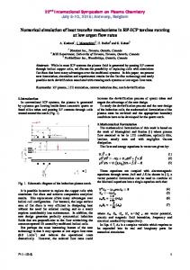
1. Introduction Prestressing or post-tensioning of structural members is favoured due to a reduced amount reinforcement required, increased span and reduced depth for flexural members, larger columnspacing and savings in construction materials cost. In post-tensioning systems, the prestressing force is transmitted to the concrete mainly by the direct bearing of a steel anchorage plate or casting on the concrete. A typical slab edge anchorage assembly is presented in Figure 1. At the dead-end, the strands coming out of the duct tube are spread out and are bent with their ends to form the shape of an ‘onion’. The anchorage zone of a post-tensioned concrete slabs is a critical portion. One major issue with the post-tensioning of slabs is the failure of the concrete material at the anchorage zone locations. Failures happen due to stress concentrations in spite of factors of safety and heavy reinforcement, usually in the form of loops or spirals, as shown in Figure 1. A typical anchorage zone failure in a post-tensioned suspended slab is shown in Figure 2. The failures, which mostly happen during the post-tensioning process, can be serious and explosive in nature. They happen at the second stage of post-tensioning at either of live or dead-end anchorages. As can be seen in Figure 2, they require resources for replacement and repair which can substantially increase the construction cost. This paper reports the results of numerical simulation conducted to investigate the behaviour of anchorage zone concrete. Experiments were also carried out in an attempt to obtain the input parameters necessary for the finite elements and to validate the models.
Figure 1: Anchorage in slab edge (dimensions, mm)
Figure 2: Failed anchorage in slab edge photographed on construction site
2. Bond Mechanism For a reinforced concrete member, the following expression for a straight rebar anchored in concrete has been reported derived from the equilibrium of the concrete and bar forces (for e.g., see Mendis and French (2000):
A b f s d b l d
(1)
where, Ab and db are the area and diameter of the rebar, ld is the bond length of rebar, fs is the stress developed in the rebar, and τ is the average bond stress. The average bond stress can be related to the bar diameter, bar stress and bond length by simplifying Equation (1):
f s db 4ld
(2)
This formula is used to determine the average bond stress developed between the rebar (fibre) and concrete (matrix). The rebar force is transferred to the concrete by adhesion, friction and mechanical bearing between the deformations and the surrounding matrix (Warner et al. 1998). An experimental study of bond strength of plain reinforcing bars in OPC-based concrete has been reported previously (Mo and Chan, 1996). It is found, in the absence of the ribs (as present in most reinforcements), the pullout resistance would mainly rely on the adhesive property of the concrete and the friction force. Gustavson (2004) reported experimental results on bond response of indented and smooth threewire and single-wire strands. The study presented the bond response of strands with various wire surface treatments and geometries of the strand. It was established that micro roughness of the surfaces of the strand strongly affected the initial bond response of the strand. The density of concrete was, however, a better parameter to investigate the influence of concrete properties on bond with strands rather than compressive strength. Their findings correspond with the findings of Chapman and Shah (1987) who have reported little correlation between bond strength and compressive strength for smooth steel bars indicating that adhesive component of bond is relatively independent of compressive strength for smooth bars. It is generally accepted that for
deformed bars, compressive strength is an important parameter when considering bond behaviour of reinforcing bars. In a more recent study, Xue et al. (2008) have examined the bond properties of high-strength carbon fiber-reinforced polymer (CFRP) strands in different bonding agents and have compared them to that of steel strands. The purpose of Xue et al.’s investigation was to present a model that represents bonding of the CFRP with that of concrete. Somewhat con-trary to Gustavson’s conclusions, Xue et al. (2008) found a direct relationship between compressive and bond strength properties with strands. It was found that higher compressive strengths develop higher bond strengths.
3. Bond Model The application of the interface elements in this model is shown schematically in Figure 3. Nodes 1 to 3 in Figure 4 are the nodes number of the wire/ strand and Nodes 4 to 6 are the nodes number of the concrete material. Nodes 1, 2 and 3 of the wire/ strand are connected to Nodes 4, 5 and 6 of concrete material respectively via interface element. Node 1 and Node 4 may have the same coordinate or has zero distance. The interface element used in this model has springs in tangential and normal directions.
Figure 3: Interface element model for bond-slip behaviour between strand/wire and concrete (showing only the tangential spring for simplicity)
Figure 4: Application of the interface elements The bond stress-displacement relationship model as shown in Figure 5 is proposed for interface element of wire. This model is derived by curve fitting experimental data. A numerical
simulation is conducted to validate the proposed bond stress-displacement relationship of wire. The values of coefficient a and the peak bond strength (τ3) values are listed in Table 1. The simulation is conducted using non-linear finite element analysis. Software Diana 9.3 (Witte and Kikstra, 2008) was used for the analysis. Similar to the wire, a bond stress-displacement relationship for strand is proposed in Figure 5b. Equally, derived from regression analysis of the experimental data, the model is constituted from three distinct phases. OA is the linear part of the stress-displacement relationship. AB is based on experimental data, BC is the strain hardening part and C is the point of failure, after which the strand would have the ability to carry very limited load.
(a)
(b)
Figure 5: Bond stress-displacement relationship of wire
Table 1: Model parameters Concrete age (Day)
a
τ3
4
2.18
0.0218fcm
7
2.60
0.0290 fcm
21
3.68
0.0340 fcm
The engineering properties of concrete are presented in Table 2. The properties are calculated from the tests carried out following the relevant Australian Standards. The values presented in the table are the average results of three specimens tested.
Table 2: Engineering properties of the concrete Age
f'c
fsts
E
ν
Gf
(Days)
(MPa)
(MPa)
(MPa)
4
31.7
3.15
16805.0
0.15
82.8
7
38.0
3.24
21485.0
0.17
87.4
21
50.0
3.46
21548.5
0.18
96.2
N/m
The experimental results have been compared to the results of the finite element analyses. It was shown that the model can reasonably predict the bond slip behaviour of both strand and wire (Sofi at al., 2011).
4. Experimental Work Beam dimension and the location of the reinforcements are presented in Figure 6. In this beam, the onion is located close to the surface that the exposed to the air. The remaining five sides of the mould are thermally confined with plywood. The location of the onion next to the ‘exposed’ surface has implications both at the structural and materials levels. The rationale for structural effects is similar to those reported for bond strength calculation. Beam-end specimens allow the ‘onion’ to be situated in an area of flexural tension when the pullout load is applied reducing the confinement effects provided by the support reactions. This innovative test method for dead-end anchorage is based on ASTM A 944-99 (2000) which is set for evaluation the bond performance of reinforcements in concrete.
a) Front
Figure 6: Dimensions used for the model
b) Side
At material level, the anchorage is situated close to the surface of the concrete member. It replicates a rather critical case, where the cover-to-surface of the anchor is rather small. The concrete is therefore exposed to the ambient environments and its properties are defined by the outside environments. In order to account for the early age properties, the model, therefore, needs to account for the heat diffusion through boundary mediums such as formwork and the exposed surface. The most important feature of the beam-end model is the onion. The onions are made up of 7wire 12mm diameter strands (see Figure 7). The selected dimensions of the onions are based on the average measurements of typical onions made on construction site.
Figure 7: Dimensions of the onion (mm)
It should be noted that the beam-end specimens are not intended to reflect the general reinforcement arrangement in a prestressed anchorage zone. The tests are carried out to evaluate the failure mechanisms of an onion under unconfined conditions. The pullout load direction and the supports are depicted in Figure 8. In the figure, the gravity supports which are positioned in the three corners away from the location of the anchor are omitted.
Figure 8: Beam-end specimen: (a) Beam-End Specimen undergoing test; and, (b) Loading and Supports
5. Modelling Aspects The finite element model of dead-end anchor is shown in Figure 9. The pyramid element is selected for concrete. Bond between the wire or strand and concrete are modelled using interface element. Since the displacement of the wire and strand of particular importance to this study, they are modelled using trusses and the bond between wire/ strand and the surrounding concrete material is modelled using interface elements. The model making involves making the reinforcement that represents the anchor and the onion and the surrounding reinforcements. The reinforcement that represents the reinforcement in the box other than the strand and the onion are assumed to be embedded. It means that the displacement of the reinforcement is assumed to be the same with the surrounding concrete material. The analyses are conducted using nonlinear finite element method. Program Diana 9.3 (Witte and Kikstra, 2008) is employed for the analyses.
Figure 9: Finite element model and meshing
6. Numerical Results The strain-load relationships for concrete elements surrounding the anchorage recorded while applying the load are compared with the model results (Figure 10). The tensile strain is introduced by the bond strength of the stand with the concrete. Afterwards, when the load is transferred to the onion, the concrete elements at location 1 and 2 experience a compressive stress. It is also interesting to note that strain gauge closer to the surface gauge 1, demonstrates higher strains compared to the one positioned further from the surface, gauge 2. This is as a result of the radial stresses imposed by the onion on the concrete and the effect of confinement by the surrounding concrete. As the load approaches the ultimate load of 105kN, both the loadstrain curves tend to be a plateau describing the state of concrete cracking. At this stage, large cracks are visible at the concrete surface and tend to propagate quickly.
Side
Top view
(a)
(b)
Figure 10: (a) strain gauge locations with respect to the onion; and, (b) load-strain results The analysis is conducted using deformation controlled procedure. The results of Figure 10(b) show that the FEM model prediction is consistent with the experimental results. The negative values of micro-strain indicate the strain gauges or in case of the model, the concrete elements are in compressive and the positive values indicate the tension state. Experimentally, it was observed that the beam-end specimens with dead-end onion anchors failed in an explosive manner consistent with the actual failure modes reported on the construction sites. A splitting type failure was observed, dislodging large pieces of concrete surrounding the onion (Sofi et al., 2008). The crack development pattern described in Figure 11 confirms the experimental observations. The first cracks have appeared next to the supports restraining the pullout load. The main failure cracks appeared on the surfaces closest to the onion. It can be seen that the damage starts at the straight part of the anchorage assembly, that is, along the strand. The main cracks however, appear on the concrete surface next to the onions. From the numerical results and the crack propagation pattern, a number of observations can been made: the failure mechanism starts with debonding of strand; the concrete within the onion is pulled out from the surrounding concrete; concrete cracks are present inside and around the onion as pointed; the locations where the wires of the onion merge and at the locations the wire are bent appear to have been crushed or highly stresses, and wires can be observed. In summary, the onion and the concrete within the onion appear to be an isolated unit. As the loading continues, this isolated unit appears to induce radial stresses due to interlocking of the onion and the surrounding concrete. It is clear from the results presented that even at the low level loads (47kN), the cracks and damage in the concrete next to the onion is noticeable. This is at a much lower load compared to the actual load that is normally imposed on the concrete. That is at the second stage, post-tensioning load can reaches about 96kN for one of the onions. Clearly, the concrete within the post-tensioned member will be damaged, even though this crack may not appear at the surface or be noticeable.
P= 16 kN
P=68 kN
P=98 kN
Figure 11: Crack propagation of pull out analyses
P=47 kN
P=88 kN
P=107 kN
7. Conclusion The numerical simulations of dead-end anchor behaviour of suspended slabs have been presented in this paper. The cracks propagation on the anchorage zone of PT members has been clearly simulated. The numerical simulation results on the anchorage zone of PT members show that the crack developed on the concentrate area near the dead end anchors. The results are very close to that of obtained from the experimental works. The model adopted was found to be able to reasonably predict the pullout load displacement behaviour of strand and wire in concrete.
References ASTM A 944-99, (2000). 'Standard Test Method for Comparing Bond Strength of Steel Reinforcing Bars to Concrete Using Beam-End Specimens', Annual Book of ASTM Standards. (West Conshohocken, United States). Chapman R. A. and Shah, S.P. (1987). ‘Early age bond strength in reinforced concrete’, ACI Materials Journal, 84(6) 501-510. de Witte, F.C. dan Kikstra, W.P. Ed. (2008). “DIANA Finite Element Analysis. User’s Manual: Release 9.3”, TNO Building and Construction Research, Delft. The Netherlands. Gustavson, R., (2004). 'Experimental studies of the bond response of three-wire strands and some influencing parameters', Materials and Structures/Materiaux et Constructions 3796-106. Mendis, P. A. and French, C. W. (2000) 'Bond strength of reinforcement in high-strength concrete', Advances in Structural Engineering Journal 3(3) 245-253. M. Sofi, P. A. Mendis, D. Baweja, Elvira, (2011), ‘Bond performance of strand and wire in early age concrete’, In proceedings: Symposium on High Performance Concrete - Design, Verification & Utilization, ed., M.Khrapko, Rotorua, New Zealand. Mo, Y. L. and Chan, J. (1996). 'Bond and Slip of Plain Rebars in Concrete', Journal of Materials in Civil Engineering 8(4) 208-211. Sofi, M, Mendis, P and Baweja, D. (2008). 'Behaviour of post-tensioning anchorage zones in early age concrete: Experi-mental Study', in Proceedings of the Australasian Confer-ence on Mechanics of Solids and Materials (ACMSM), University of Southern Queensland, Toowoomba, Australia. Van Breugel, K.. (1997). 'Simulation of hydration and formation of structure in hardening cement based materials', (Delft University Press, Netherlands). Warner, R. F., Rangan, B. V., Hall, A. S. and Faulkes, K. A. (1998) 'Concrete Structures', (Melbourne). Xue, W., Wang, X., Zhang, S. (2008). 'Bond Properties of High-Strength Carbon FibreReinforced Polymer Strands', ACI Materials Journal 105(1) 11–19.