heat transfer in a lid-driven square cavity is investigated · numerically by using the finite volume method. A two- · dimensional vertical lid driven square enclosure ...
Published by : http://www.ijert.org
International Journal of Engineering Research & Technology (IJERT) ISSN: 2278-0181 Vol. 6 Issue 08, August - 2017
Numerical Simulation of Hydromagnetic Convection in a Lid-driven Cavity Containing a Heat Conducting Elliptical Obstacle with Joule Heating Dipan Deb*, Sajag Poudel, Abhishek Chakrabarti Department of Aerospace Engineering Indian Institute of Technology Kanpur Kanpur, Uttar Pradesh, India
Abstract—The hydromagnetic mixed convection flow and heat transfer in a lid-driven square cavity is investigated numerically by using the finite volume method. A twodimensional vertical lid driven square enclosure with a centrally located heat conducting elliptical obstacle is adopted to simulate the steady, laminar and incompressible flow. Two different sizes of the obstacle are considered with an aim to enhance the heat transfer rate. The governing equations are solved by using the Semi-Implicit Method for Pressure Linked Equations (SIMPLE) algorithm. The left and right vertical walls of the cavity are kept isothermal at two different temperatures whereas both the top and bottom horizontal walls are thermally insulated from the surroundings. Furthermore, a uniform horizontal magnetic field is applied, perpendicular to the translating left lid. The investigations are carried out for a number of governing parameters such as the Hartmann Number, Reynolds Number, Richardson Number, Joule heating parameter and Prandtl Number. Two cases of translational lid movement, viz., vertically upwards and downwards are undertaken to study the conjugate heat transport process. The flow and thermal fields are analysed by means of streamline and isotherm plots. Keywords— Hydromagnetic Mixed Convection, Joule Heating Parameter, Lid-Driven Square Cavity, Magnetic Field
I.
INTRODUCTION
Mixed convection flows and heat transfer in lid-driven cavities have widespread scientific and engineering applications such as heat exchangers, cooling of electronic components, industrial float glass production, lubrication and drying technologies, food processing, solar ponds, nuclear reactors, etc. Prasad and Koseff (1996) [12] experimentally investigated the mixed convection within a deep lid driven cavity of rectangular cross-section and varying depth. Chamkha (2002) [1] investigated the unsteady laminar hydromagnetic convection in a vertical lid-driven square cavity with internal heat generation or absorption for both aiding and opposing flow situations. Cheng and Liu (2010) [2] elaborated the effects of temperature gradient on the fluid flow and heat transfer for both assisting and opposing buoyancy cases. Billah et al. (2011) [3] and Khanafer and Aithal (2013)
IJERTV6IS080055
[4] highlighted the role of an obstacle inserted into the cavity as an important enhancer of heat transfer. Later on, Chatterjee et al.(2013) [5] and Ray and Chatterjee (2014) [6] also studied the effects of an obstacle on the hydromagnetic flow within a lid-driven cavity. Cheng (2011) [7] numerically investigated a lid-driven cavity flow problem over a range of Prandtl Numbers. Al-Salem et al. (2012) [8] studied the effects of the direction of lid movement on the MHD convection in a square cavity with a linearly heated bottom wall. Omari (2013) [9] simulated a lid driven cavity flow problem at moderate Reynolds Numbers for different aspect ratios. Ismael et al. (2014) [10] investigated the convection heat transfer in a liddriven square cavity where the top and bottom walls were translated horizontally in two opposite directions with varying values of partial slip. Khanafer (2014) [11] emphasized on the flow and thermal field in a lid-driven cavity for both flexible and modified heated bottom walls. However, the effects of a centrally placed obstacle on the hydromagnetic convection within a lid driven cavity were yet to be studied. Hence, motivated by previous works, the present study deals with the numerical simulation of a vertical lid-driven square cavity containing a heat conducting vertical elliptical obstacle and permeated by a transverse magnetic field.
List 1. Nomenclature of different parameters
Re Gr Ri Ha Ec N J Pr Nu 𝜽avg
NOMENCLATURE Reynolds Number Re = V0L/𝜈 Grashof Number Gr = gβ(Th-Tc)L3/ 𝜈 2 Richardson Number Ri = Gr/Re2 Hartmann Number Ha=B oL√𝜎/𝜌ν Eckert Number Ec = Vo2/cp(Th-Tc) Interaction parameter for MHD N = Ha2/Re Joule heating parameter J = N*Ec Prandtl Number Pr = 𝜈 /α Nusselt Number Nu = hL/kf θ Average fluid temperature 𝜽avg = ∫ 𝑑𝑉
www.ijert.org (This work is licensed under a Creative Commons Attribution 4.0 International License.)
𝑉
99
Published by : http://www.ijert.org
International Journal of Engineering Research & Technology (IJERT) ISSN: 2278-0181 Vol. 6 Issue 08, August - 2017
(a)
(b) Fig. 1. Schematic representation of the physical model for both obstacle sizes along with the boundary conditions for (a) upward lid motion and (b) downward lid motion.
II.
PHYSICAL MODEL
𝑢
The model describes a two-dimensional lid-driven square enclosure filled with an electrically conducting fluid (air at 𝑃𝑟 = 0.71) and having a centrally located heat conducting solid vertical elliptical obstacle. The top and bottom horizontal walls are thermally insulated from the surroundings. The left and right vertical walls are kept at temperatures, 𝑇𝑐 and 𝑇h, respectively where 𝑇𝑐 < 𝑇h. The left wall is translated vertically upwards as well as downwards in its own plane at a constant velocity 𝑉0 while all the other walls are kept stationary. A uniform magnetic field 𝐵0 is applied horizontally, perpendicular to the left lid. The density variation in the buoyancy term is assumed to be taking place according to the Boussinesq hypothesis while all dissipative phenomena except Joule heating are neglected III.
GOVERNING EQUATIONS
The dimensional forms of the governing equations are as follows:
𝜕𝑥
+
𝜕𝑣 𝜕𝑦
=0
IJERTV6IS080055
+𝑣
𝜕𝑥 𝜕𝑣
+𝑣
𝜕𝑥
𝜕𝑢 𝜕𝑦 𝜕𝑣 𝜕𝑦
=− =−
1 𝜕𝑝 𝜌 𝜕𝑥 1 𝜕𝑝 𝜌 𝜕𝑦
+ 𝜐(
𝜕2 𝑢 𝜕𝑥 2 𝜕2 𝑣
+𝜐(
𝜕2 𝑢
+
𝜕𝑥 2
+
)
𝜕𝑦 2 𝜕2 𝑣
𝜕𝑦 2
)−
𝑔𝛽(𝑇 − 𝑇𝑐 ) 𝑢
𝜕𝑇
+𝑣
𝜕𝑥
𝜕𝑇 𝜕𝑦
= 𝛼(
𝜕2 𝑇 𝜕𝑥 2
+
𝜕2 𝑇 𝜕𝑦 2
(2) 𝜎𝐵𝑜 2 𝜌
𝑣+ (3)
)+
𝜎𝐵0 2 𝜌𝑐𝑝
𝑣2
(4)
For the solid zone: 𝜕2 𝑇𝑠 𝜕𝑥 2
+
𝜕2 𝑇𝑠 𝜕𝑦 2
=0
(5)
In order to non-dimensionalize the governing equations, the following non-dimensional parameters are introduced. 𝑥 𝑦 𝑢 𝑣 𝑝 𝑋 = ,𝑌 = ,𝑈 = ,𝑉 = ,𝑃 = 𝐿 𝐿 𝑉𝑜 𝑉𝑜 𝜌𝑉𝑜 2 𝑇 − 𝑇𝑐 𝑇𝑠 − 𝑇𝑐 𝜃= ,𝜃 = 𝑇ℎ − 𝑇𝑐 𝑠 𝑇ℎ − 𝑇𝑐 The dimensionless governing equations take the following form: For the fluid: 𝜕𝑈
For the fluid zone: 𝜕𝑢
𝑢
𝜕𝑢
+
𝜕𝑉
𝜕𝑌 𝜕𝑋 𝜕𝑈
(6) 𝜕2 𝑈
(
𝑅𝑒 𝜕𝑋 2
+
𝜕2 𝑈
100
𝜕𝑋
+
1
www.ijert.org (This work is licensed under a Creative Commons Attribution 4.0 International License.)
𝜕𝑌
=−
𝜕𝑃
(7)
𝜕𝑋
+𝑉
𝜕𝑈
)
(1)
𝑈
=0 𝜕𝑌 2
Published by : http://www.ijert.org
International Journal of Engineering Research & Technology (IJERT) ISSN: 2278-0181 Vol. 6 Issue 08, August - 2017
(a)
(b)
Fig. 2. Mesh distribution in the computational domain for (a) smaller vertical ellipse and (b) bigger vertical ellipse of surface area 2.25 times the area of the smaller ellipse.
𝑈
𝜕𝑉
𝑈
𝜕𝜃
𝜕𝑋
𝜕𝑋
+𝑉
𝜕𝑉
+𝑉
𝜕𝜃
𝜕𝑌
𝜕𝑌
=− =
𝜕𝑃 𝜕𝑌
1
+ (
1
(
𝜕2 𝑉
𝑅𝑒 𝜕𝑋 2
𝜕2 𝜃
𝑅𝑒𝑃𝑟 𝜕𝑋 2
+
+
𝜕2 𝜃 𝜕𝑌 2
𝜕2 𝑉 𝜕𝑌 2
) − 𝑁𝑉 + 𝑅𝑖𝜃
) + 𝐽𝑉
2
(8) (9)
𝜕𝑋 2
+
𝜕2 𝜃𝑠 𝜕𝑌 2
=0
(10)
The following dimensionless boundary conditions are implemented: 𝑈 = 0, 𝑉 = 1 (for upward lid motion), 𝑈 = 0, 𝑉 = −1 (for downward lid motion), 𝜃 = 0 : at the left vertical wall. 𝑈 = 0, 𝑉 = 0, 𝜃 = 1 : at the right vertical wall. 𝑈 = 0, 𝑉 = 0, walls.
𝜕𝜃
𝜕𝜃
𝜕𝑛
𝜕𝑛
( )𝑓 = 𝐾( )𝑠 : at the fluid -solid interface. Here, 𝑛 is the outward drawn unit normal to a particular solid impermeable wall surface. IV.
For the solid: 𝜕2 𝜃𝑠
𝑈 = 0, 𝑉 = 0 : at the surface of the heat conducting solid obstacle.
𝜕𝜃 𝜕𝑛
= 0 : at the top and bottom horizontal
(a)
NUMERICAL METHODOLOGY
The non-dimensional governing equations along with the aforementioned boundary conditions are solved by using a commercial finite volume-based CFD package called FLUENT. A pressure-based segregated solver is used and the pressure-velocity coupling is governed by the SIMPLE algorithm. In order to account for high gradients of the transport quantities in the vicinity of the obstacle and the cavity walls, a non-uniform grid system consisting of a close clustering of grid cells near the rigid cavity walls as well as around the obstacle is adopted for the present computational purpose.
(b)
Fig. 3. Numerical validation with Chamkha (2002) for Re = 1000, Pr = 0.71 and Gr =10 2; isotherm on the left and streamline on the right
IJERTV6IS080055
www.ijert.org (This work is licensed under a Creative Commons Attribution 4.0 International License.)
101
Published by : http://www.ijert.org
International Journal of Engineering Research & Technology (IJERT) ISSN: 2278-0181 Vol. 6 Issue 08, August - 2017
Fig. 4. Effect of Hartmann number on the streamlines for upward wall motion including both obstacle sizes.
Fig. 5. Effect of Hartmann number on the streamlines for downward wall motion including both obstacle sizes
Further, in order to assess the accuracy of the results, a comprehensive grid sensitivity analysis has been performed in the computational domain and the optimum mesh size is selected for the current simulations keeping in mind the accuracy of the numerical results and the computational convenience.
IJERTV6IS080055
For the purpose of numerical validation, the study made by Chamkha (2002) [1] for the aiding flow situation has been simulated using the present numerical scheme and compared in Figure 3. The qualitative results show good agreement with the reported literature.
www.ijert.org (This work is licensed under a Creative Commons Attribution 4.0 International License.)
102
Published by : http://www.ijert.org
International Journal of Engineering Research & Technology (IJERT) ISSN: 2278-0181 Vol. 6 Issue 08, August - 2017
Fig. 6. Effect of Hartmann number on the isotherms for upward wall motion including both obstacle sizes.
Fig. 7. Effect of Hartmann number on the isotherms for downward wall motion including both obstacle sizes
V.
RESULTS AND DISCUSSION
The hydromagnetic convective flow and heat transfer in a vertical lid-driven square cavity with two different sizes of the centrally placed heat conducting solid vertical elliptical obstacle are presented as follows in the form of streamlines and isotherms for both directions of lid motion. The simulations are performed at 𝑅𝑒 = 100, 0 ≤ 𝐻𝑎 ≤ 100, = 1, and 𝑅𝑖 = 1.
IJERTV6IS080055
Figure 4 depicts the effect of the Hartmann Number (𝐻𝑎) on the flow field by means of stream function contours. The streamlines depict two counter-rotating streamlines of unequal size. The streamlines adjacent to the left lid have a clockwise sense of rotation due to the shearing action of the moving lid by virtue of the no-slip condition imposed on the cavity walls. The streamlines adjacent to the stationary right wall have a counter-clockwise sense of rotation and arise out of thermal buoyancy due to the applied temperature differential. At 𝐻𝑎 =
www.ijert.org (This work is licensed under a Creative Commons Attribution 4.0 International License.)
103
Published by : http://www.ijert.org
International Journal of Engineering Research & Technology (IJERT) ISSN: 2278-0181 Vol. 6 Issue 08, August - 2017
(a)
(b)
(b)
(d)
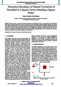
Fig. 8. Variations of average Nusselt number (Nu) with Richardson number(Ri) for (a) upward wall motion and (b) downward wall motion; variations of Non-dimensional temperature(𝜽avg) with Richardson number(Ri) for (c) upward wall motion and (d) downward wall motion.
0, the streamlines due to natural convection are somewhat bigger in size than the clockwise streamlines indicating that the flow is taking place by the combined action of shear and buoyancy. Also, a small secondary eddy due to thermal buoyancy appears just adjacent to the solid obstacle. However, as 𝐻𝑎 increases, the natural convection diminishes as the counter-clockwise streamlines gradually shrink in size and start splitting into secondary cells. Thus, the shearing effect of the moving lid gradually increases with increasing Ha as the clockwise streamlines grow bigger in size to occupy a major portion of the cavity space. Moreover, the shearing effect gets obstructed owing to the presence of the solid obstacle as there is a partial backward surge of the streamlines towards the moving lid, thereby flattening and elongating the same along the length of the left wall. At very high values of Ha, i.e., at 𝐻𝑎 = 100, the clockwise streamlines grow in size to occupy almost the entire cavity volume while the secondary cells due to buoyancy effect decompose into two small eddies at the top and bottom right corners of the cavity. This is certainly because the magnetic field has a damping effect on the natural convection flow. Qualitatively, 𝐻𝑎 has nearly identical effects on both sizes of the obstacle. But, with increase in size, the backward surge generated by collision with the obstacle increases such that the streamlines embracing the obstacle tend to grow bigger in extent whereas others shrink slightly in size and get pushed towards the cavity walls.
IJERTV6IS080055
Figure (5) depicts the streamlines for the downward wall movement which causes the aiding flow situation where the shear and buoyancy- driven convections reinforce each other. With increase in magnetic field strength, the streamlines due to shearing effect in the immediate vicinity of the solid obstacle grow in size and then split up into secondary cells near the left wall. However, due to increase in obstacle size, the streamlines in the immediate vicinity grow bigger in extent to conform to the shape and size of the obstacle. Figure (6) shows the isotherms for the upward translating left lid. At lower values of 𝐻𝑎, the convection regime is of mixed type which is depicted by higher gradients of the isotherms whereas at higher values, the isotherms become steeper and vertical which indicate that with increase in 𝐻𝑎, the heat transfer regime shifts towards quasi-conduction in the vicinity of the obstacle and pure conduction at and near the stationary right wall. Also, increase in the obstacle size leads to an increase in the conduction heat transfer process as more number of isotherms pass through the interior of the solid medium. Figure (7) shows the isotherms due to downward lid motion. Hence, due to aiding flow, the corresponding temperature gradients are more than those in Figure (6). However, once again it is observed that with increase in 𝐻𝑎, the heat transfer mechanism switches from mixed convection to pure as well as quasi-conduction at or near the solid zones of the cavity.
www.ijert.org (This work is licensed under a Creative Commons Attribution 4.0 International License.)
104
Published by : http://www.ijert.org
International Journal of Engineering Research & Technology (IJERT) ISSN: 2278-0181 Vol. 6 Issue 08, August - 2017
Figure 8(a) depicts the variations of the average Nusselt Number on the upward translating left wall with Richardson Number (𝑅𝑖 = 𝐺𝑟/𝑅𝑒2 ) for both obstacle sizes. It is found that the average 𝑁𝑢 increases with increasing 𝑅𝑖 as increase in 𝑅𝑖 corresponds to an increase in the Grashof Number (𝐺𝑟) relative to 𝑅𝑒2 thereby leading to a subsequent increment in natural convection. Thus, 𝑁𝑢 being the ratio of convection to conduction also increases. Figure 8(b) shows similar variations for the downward lid movement. The qualitative nature is equivalent to that of Figure 8(a) but with higher values of the average 𝑁𝑢 as downward wall movement leads to an aiding flow situation in contrary to Figure 8(a) where the upward wall movement causes an opposing flow situation. Also, the 𝑁𝑢 values fall slightly with increase in obstacle size due to the fact that increase in the obstacle size causes an increase in the effective heat transfer surface area of the solid medium and a decrease in the area occupied by the fluid medium thereby leading to an increase in conduction heat transfer and a subsequent decrease in convection heat transfer. Figure 8(c) shows the variations of the average fluid temperature with 𝑅𝑖 for upward wall motion. It is found that 𝜃𝑎𝑣𝑔 increases with 𝑅𝑖 up to a certain value and then falls slightly before reaching a saturation condition. This may be due to the opposing flow situation generated by upward lid motion where the shear-driven convection tries to nullify the effects of the buoyancy driven convection. The results are almost identical for bigger obstacle size but with lower values of 𝜃𝑎𝑣𝑔 as increase in size of the solid medium and a corresponding decrease in space occupied by the fluid medium leads to an increment in conduction and a subsequent fall in the convection heat transfer rate. Figure 8(d) exhibits similar variations for the downward lid motion where 𝜃𝑎𝑣𝑔 keeps on increasing with increasing 𝑅𝑖 owing to the aiding flow scenario. However, an increase in the obstacle size leads to higher values of 𝜃𝑎𝑣𝑔 which shows that increase in convection heat transfer due to assisting flow is so significant that it nullifies the adverse influence of increasing obstacle size on the values of 𝜃𝑎𝑣g. VI.
CONCLUSION
The hydromagnetic convection in a vertical lid-driven square cavity with two different obstacle sizes has been numerically investigated. It is found that the magnetic field has a damping effect on the mass transport of the working fluid and hence has a tendency to suppress natural convection. Also, the average 𝑁𝑢 increases with 𝑅𝑖 for both directions of wall movement although the increase is more for downward wall motion.
IJERTV6IS080055
Moreover, the average fluid temperature increases up to a certain value with 𝑅𝑖 and then reaches a saturation condition for upward wall motion but increases continuously for downward wall movement. Finally, due to increase in obstacle size, the 𝑁𝑢 and 𝜃𝑎𝑣𝑔 values attained are comparatively lower than those for smaller obstacle size except in the case of 𝜃𝑎𝑣𝑔 for downward wall motion where the average temperature curve for bigger obstacle size climbs above that for the smaller obstacle size.
REFERENCES [1]
Chamkha A.J. (2002) Hydromagnetic combined convection flow in a vertical lid-driven cavity with internal heat generation or absorption, Numerical Heat Transfer, Part A, 41:529-546. [2] Cheng T.S. and Liu W.H. (2010) Effect of temperature gradient orientation on the characteristics of mixed convection flow in a liddriven square cavity, Computers & Fluids, 39, 965-978. [3] Billah M.M., Rahman M.M., Sharif U.M., Rahim N.A., Saidur R., Hasanuzzaman M. (2011) Numerical analysis of fluid flow due to mixed convection in a lid-driven cavity having a heated circular hollow cylinder, International Communications in Heat and Mass Transfer, 38, 1093- 1103. [4] Khanafer K. and Aithal S.M. (2013) Laminar mixed convection flow and heat transfer characteristics in a lid-driven cavity with a circular cylinder, International Journal of Heat and Mass Transfer, 66, 200-209. [5] Chatterjee D., Halder P., Mondal S., Bhattacharjee S. (2013) Magnetoconvective Transport in a Vertical Lid-Driven Cavity Including a Heat Conducting Square Cylinder with Joule Heating, Numerical Heat Transfer, Part A, 64:1050-1071. [6] Ray S. and Chatterjee D. (2014) MHD mixed convection in a lid-driven cavity including heat conducting circular solid object and corner heaters with Joule heating, International [7] Cheng T.S. (2011) Characteristics of mixed convection heat transfer in a lid-driven square cavity with various Richardson and Prandtl Numbers, International Journal of Thermal Sciences, 50, 197-205. [8] Al-Salem K., Öztop H.F., Pop I., Varol Y. (2012) Effects of moving lid direction on MHD mixed convection in a linearly heated cavity, International Journal of Heat and Mass Transfer, 55, 1103-1112. [9] Omari R. (2013) CFD simulations of lid driven cavity flow at moderate Reynolds Number, European Scientific Journal, vol.9, No.15. [10] Ismael A.M., Pop I., Chamkha A.J. (2014) Mixed convection in a liddriven square cavity with partial slip, International Journal of Thermal Sciences, 82, 47-61. [11] Khanafer K. (2014) Comparison of flow and heat transfer characteristics in a lid-driven cavity between flexible and modified geometry of a heated bottom wall, International Journal of Heat and Mass Transfer, 78, 1032-1041. [12] Prasad A.K. and Koseff J.R. (1996) Combined forced and natural convection heat transfer in a deep lid-driven cavity flow, Int. J. Heat and Fluid Flow, 17:460-467.
www.ijert.org (This work is licensed under a Creative Commons Attribution 4.0 International License.)
105