engine. This paper deals with numerical simulation of a double acting alpha-type. Stirling engine (DASE), which has four cylinders with four pistons moving.
SCIENCE & TECHNOLOGY DEVELOPMENT, Vol 18, No.K7- 2015
Numerical simulation of performance of a double-acting alpha-type stirling engine
Nguyen Truong Chin-Hsiang Cheng Yen-Fei Chen
Department of Aeronautics and Astronautics, National Cheng Kung University,Tainan, Taiwan ROC. (Manuscript Received on July 13th, 2015; Manuscript Revised October 16th, 2015)
ABSTRACT Computational Fluid Dynamics (CFD) analysis is one of the most important powerful processes in commercial engine project, which is going to give the engineers the overall vision that a simulator may want to know about. It could save lots of time and costs before people actually manufacture the engine. This paper deals with numerical simulation of a double acting alpha-type Stirling engine (DASE), which has four cylinders with four pistons moving respectively. In the engine, double actions of the four pistons take place in two opposite chambers in each of four cylinders. For each cycle, the piston alternately moves backand-forth in a cylinder by the connecting
expansion chamber of a cylinder to the compression chamber of the next cylinder with a channel, the pressure difference between the expansion and compression chambers is increased and the power capacity of the engine is improved. In this paper, the numerical module is built based on the frame of commercial CFD software (FLUENT). The user-defined functions (UDFs) of the software are adapted so that the movement of those pistons in those cylinders can be simulated. Periodic changes in temperature, pressure and velocity fields in the engine are predicted and the power output of engine is obtained.
Key words: Double acting alpha-type Stirling engine, CFD, Stirling engine. 1. INTRODUCTION The idea of double acting alpha-type Stirling engine which original created with four cylinders but in one cylinder have two chambers, expansion room (hot space) and compression room (cold space). The adjacent cylinders would be connected to the behind cylinders after throughout the regenerators. Each cylinder has only one piston which can move from the top dead center (TDC) point to bottom dead center Trang 14
(BDC) point to create the swept volume in other room. The four pistons can be driven by apply any mechanism systems, whichever can make the sinusoidal motions of multi-pistons by the phase angle differences of adjacent pistons in the engine, for example the crankshaft system and swash-plate system…etc. The models are designed with the exact fluids occupied by the volumes inside the engine.
TAÏP CHÍ PHAÙT TRIEÅN KH&CN, TAÄP 18, SOÁ K7- 2015
The primer design has 4 modules within hot chamber (fluid in the expansion chamber), cold chamber (fluid in the compression chamber), and regenerator (fluid in the regenerator) and pipes (fluid occupied in the pipes which connected hot chamber and cold chamber to regenerator).
a) a)
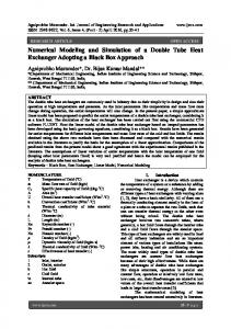
Each module has the same structure and working principles but the phase angle is 90 degree difference between these modules (shown on Figure 1), so that total volume of each module is not the same at the start point. At the beginning, two modules are at the smallest volume (pressing) and two other modules are at the biggest volume (stretching).
Circular configuration of DASE Circular configuration of DASE
b) Liner configuration of DASE Figure 1. The different configurations of DASE
Trang 15
SCIENCE & TECHNOLOGY DEVELOPMENT, Vol 18, No.K7- 2015
2. METHODOLOGY 2.1. Piston displacement For the determination of sinusoidal motion of those 4 pistons in simulation, the analysis trajectories of those pistons are a necessary process. The displacements of four pistons in alternate cylinders can be seen in Figure 1, it can be written following as bellow: (1) r cos S r sin L cos sin 1 ; 1 L (2) r sin S r cos L cos sin 1 ; 2 L
r cos S r sin L cos sin 1 ; 3 L
(3)
r sin S r cos L cos sin 1 ; 4 L
(4)
where, α is the phase angle; r is the radius; is the length of connecting rod; S 1 , S 2 , S 3 , S 4 L are the straight trajectory of these 4 pistons. 2.2. Volume variation In a DASE model there are 4 modules, one module consisting of compression chamber, expansion chamber and regenerator. Those theoretical thermodynamics model of each module are the same as sinusoidal variation so that in this section, theoretical study of one unit module analytical studied model as others. These total expansions space and total compressions space can be calculated as equations below: V H I V Hd
V Sh 1 cos t 2
(5)
VC I VCd
VSc 1 cos t 2
V C II V C d
V Sc 2
V C III V C d
V Sc 1 cos t 2
V C IV V C d
V Sc 2
(9)
3 1 cos t 2
1 co s t 2
(10) (11)
(12)
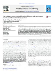
where, VH is expansion space volume variation, VC is compression space volume variation, VHd is expansion death volume, VCd is compression death volume, VSh is swept volume of expansion space, VSc is swept volume of compression space. Thermodynamic of this model calculated by the consideration on three main spaces are hot chamber (CV-hot), cold chamber (CV-cold) and regenerator space [1]. The volumes of hot chamber and cold chamber are not stationary; its variable due to piston’s displacements all the time but the volume of regenerator is constant. 2.3. A control volume of DASE In the Figure 2 shows a control volume (CV) in a DASE which called one module. The CV design includes hot chamber (fluid in the expansion chamber), cold chamber (fluid in the compression chamber), and regenerator (fluid in the regenerator) and pipes (fluid occupied in the pipes which connected hot chamber and cold chamber to regenerator), which are the exact fluids occupied by the volumes inside the engine. 2.4. Working condition
VH II VHd
V Sh 2
1 cos t 2
VH III VHd
VSh 1 cos t 2
VH IV VHd
VSh 2
Trang 16
3 1 cos t 2
(6) (7) (8)
The operation of Stirling engine [2] can be controlled by the different levels of heat sources from both of expansion room and compression room. The net work done can be adjusted by many ways such as initial pressure in charge, variation of volume including dead volume in each room, variation of temperature of heat sources, etc.
TAÏP CHÍ PHAÙT TRIEÅN KH&CN, TAÄP 18, SOÁ K7- 2015
Figure 2. A control volume in a DASE
Table 1. Dimensional design of base-line case Expansion cylinder & piston Bore Stroke Swept volume
70 50 192
mm
Compression cylinder & piston Bore Stroke Swept volume
70 50 192
mm
Regenerator Diameter length Volume filling up in fact
20 50 14
mm mm
Connected Pipe Diameter Total length Volume filling up in fact
8 210 10
mm mm
mm cm 3
mm cm 3
cm 3
cm 3
Table 2. Working conditions of DASE
(mm)
Regenerator Porosity (%)
S (mm)
Ω (rpm)
70
0.9
50
750-1500-3000
P (atm)
TH
TL
D e ,c
(K)
(K)
1-3-5
1200
300
Trang 17
SCIENCE & TECHNOLOGY DEVELOPMENT, Vol 18, No.K7- 2015
500
Case 1 P=1atm
11 Module I
Module III
Module II
450
Module IV
Module I
Module II
400
Volume [cc]
Pressure [atm]
9
Module IV
Module III
7
5
350
300
250 3 200
90
180
270
150
360
90
180
Crank Angle [deg]
270
360
Crank angle [deg]
Figure 3. Volume variations of 4 modules in cycle
22
Figure 4. Pressure variations of 4 modules in cycle
500
P=5atm P=3atm P=1atm
20
36 Work done per cycle Power output
18
34
450 32
14
30
400
P [W]
Pressure [atm]
16
12 10
28 350
26
8 24
6 300 4
22
2 100
150
200
250
300
350
400
250
450
0
1
2
3
Volume [cc]
4
5
6
Figure 5. PV diagrams of each module in different
Figure 6. Work done per cycle and power
charged pressures in a cycle
output at different charged pressures
Besides, the working fluid used inside those chambers is considered as air, hydrogen and nitrogen; they have almost the same thermodynamic proprieties [3] so that the performance in a Stirling cycle [4] also must be similar. The advantages of nitrogen is reduces the explosion factor under working and the hydrogen can creates high engine’s efficiency but the main purpose that we had used air as working fluid because it is likely as the normal environment and during the time life cycle of engine it is not only reduce the maintenance fee but also can make the longer life time for the engine. Trang 18
20
P [atm]
3. RESULT AND DISCUSSION In this paper, the results obtained at primer design which can be seen in Table 1. The design of engine cylinder diameter and stroke are fixed. We do investigate the effects of power output and energy to improve the performance of engine. The work done per cycle can be calculated as the following formula: W
PdV PdV P dV P dV P dV 1
c
c
1
2
c
2
3
c
3
4
c
4 PdV 1 1 c
(13)
4
W [J]
1
TAÏP CHÍ PHAÙT TRIEÅN KH&CN, TAÄP 18, SOÁ K7- 2015
At high charged pressure and low rotation speed of engine, the performance of engine is increased as the difference in pressure between the lowest and the highest point in the PV diagram is larger. Morever, the area enclosed by PV diagram also becomes bigger. The effect of charged pressure also influences to obtain better indicated work. By the ideal gas equation PV mRT , while the specific gas R is constant, the initial volume and the initial temperature are the same;the change of initial pressure will directly affect the quality of the initial mass. By that mean, the variation of pressure will change the quality of initial mass so if the power output per unit mass fixed, more quality of initial mass charged which will create more power output of Stirling engine. Figure 7 is the influence of charged pressure to work done and power output, which shows the greater of the charged pressure,
will create the higher result of power output and work done. To know about the performances of engine, the investigation effect of speed engine is necessary, in this paper the performance of engine bases on the affection of speeds engine have shown on. The best performance of this engine given at rotation speed of engine around point 1500rpm, even though the indicated work done at this speed does not perfect. Its indicated work is smaller than the one created by the lower of speed engine and higher speed engine. The important issue has also explored is the negative work will be created when the rotation speed of engine increases too high. So that, to reach the highest engine efficiency, the operation engine at this point is possible.
600
25 Work done
500
20
400
15
300
10
200
5
100
0
0
750
1500
2250
3000
W [J]
P [W]
Power output
-5
Speed [rpm] Figure 7. Work done and power output in a cycle at different rotation speeds of engine
Trang 19
SCIENCE & TECHNOLOGY DEVELOPMENT, Vol 18, No.K7- 2015
4. CONCLUSIONS The complete construction of threedimensional computational fluid dynamics simulation is based on solving the dynamic boundaries problem of the heat distribution and flow fields in the cylinder of double acting α-type Stirling engine. The design, simulation and analysis processes were done by using the numerical simulation model software (FLUENT). Using one of the most advanced simulation software ANSYS FLUENT [5] has brought much benefits and given us an useful observation on setting the reliable working conditions, also verification the unreal working
conditions. The analyses are considered making heat transfer fluid inside the cylinder, ignoring the heat conduction wall. Setting heat source boundary conditions and assumptions are forwarded to low temperature working engines [6]. The results such as average temperature, average pressure, and average mass continuity are written out with the match up to variation of volume at the differences of time, it is getting close to the real engine and improved the results. Acknowledgement: Financial support from the Ministry of Science and Technology, Taiwan, under grant MOST104-2622-E-006-011-CC2 is greatly appreciated.
Mô phỏng số tính năng công suất của động cơ stirling tác động kép loại alpha Nguyễn Trường Chin-Hsiang Cheng Yen-Fei Chen Khoa Hàng Không và Vũ Trụ, Trường ĐH Quốc Gia Cheng Kung University, Đài Loan
TÓM TẮT Phần mềm tính toán CFD (Computational Fluid Dynamics) được biết đến là một trong những công cụ mạnh và hữu hiệu để hỗ trợ thiết kế các mẫu động cơ mới có tính thương mại, phần mềm này thông qua các giả lập sẽ cung cấp cho các kỹ sư tầm nhìn tổng thể trong quá trình thiết kế. Nó có thể tiết kiệm rất nhiều thời gian và chi phí trước khi thực hiện chế tạo mẫu thực. Công trình nghiên cứu này trình bày phương Trang 20
pháp mô phỏng số cho động cơ Stirling loại alpha tác động kép (DASE), trong đó có bốn xy-lanh với bốn piston chuyển động tương ứng. Trong mỗi động cơ, tác động kép của bốn piston diễn ra trong hai buồng đối diện trong mỗi bốn xy-lanh. Đối với mỗi chu kỳ, piston luân phiên di chuyển qua lại trong một hình trụ thông qua các kết nối buồng giãn nở của một xy-lanh tới buồng nén của hình trụ tiếp theo với một kênh, chênh lệch áp suất
TAÏP CHÍ PHAÙT TRIEÅN KH&CN, TAÄP 18, SOÁ K7- 2015
giữa buồng giãn nở và buồng nén được tăng lên và cải thiện công suất của động cơ. Trong bài báo này, các mô-đun số được xây dựng dựa trên khung của phần mềm CFD thương mại (FLUENT). Các chức năng người dùng định nghĩa (UDFs) của phần
mềm được sửa đổi phù hợp để mô phỏng chuyển động của các piston trong các xylanh. Các thay đổi định kỳ của các trường nhiệt độ, áp suất và vận tốc trong động cơ được dự đoán và ghi nhận giá trị công suất đầu ra của động cơ.
Từ khóa: Động cơ Stirling loại alpha tác động kép, CFD, Động cơ Stirling.
REFERENCES [1]. Campos, M., J. Vargas, and J. Ordonez, Thermodynamic optimization of a Stirling engine, Energy, 44(1): p. 902-910, 2012. [2]. Reader, G.T., Stirling engines, 1983. [3]. Reid, R.C., J.M. Prausnitz, and B.E. Poling, The properties of gases and liquids, 1987. [4]. Urieli, I. and D.M. Berchowitz, Stirling cycle engine analysis, Taylor & Francis, 1984.
[5]. Fluent, A., 14.5, Theory Guide; ANSYS. Inc., Canonsburg, PA, 2012. [6]. Alberti, F. and L. Crema, Design of a new medium-temperature Stirling engine for distributed cogeneration applications, Energy Procedia, Vol. 57, pp.321-330, 2014..
Trang 21