Numerical simulation of rectangular dropshafts using a Volume-of-Fluid (VoF) technique Vitor Sousa1,4, Fabián A. Bombardelli2 and Hubert Chanson3 1
Instructor, PhD Student, Departamento de Engenharia Civil e Arquitectura, Instituto Superior Técnico, Av. Rovisco Pais, 1049-001 Lisboa, Portugal, Tel: +351 933 755 084, Email:
[email protected] 2 Assistant Professor, Department of Civil and Environmental Engineering, University of California, Davis, 2001 Engineering III, One Shields Ave., Davis, CA 95616, USA 3 Professor, the University of Queensland, School of Civil Engineering, Brisbane QLD 4072, Australia, Email:
[email protected] 4 Former Visiting Scholar, Department of Civil and Environmental Engineering, University of California, Davis, 2001 Engineering III, One Shields Ave., Davis, CA 95616, USA Abstract This paper focuses on the implementation, validation and exploitation of a vertical dropshaft flow operation using the commercial VOF-based Computational Fluid Dynamics (CFD) code, FLOW-3D®. Using the experimental data of Chanson (2002), the package was used to simulate the flow patterns in a rectangular dropshaft with plunge-flow pattern. Both k−ε and k−ε RNG turbulence closures were tested and the computed hydraulic parameters were found to be in good agreement with the experimental observations. The results demonstrate that the CFD modeling of rectangular plunge-flow dropshaft hydraulics is viable and useful to evaluate the hydraulic parameters of fundamental importance when modeling collection systems in one dimension. INTRODUCTION Dropshafts are commonly found in collection systems for conveying stormwater or wastewater from an upper level to a lower level in cities which have noticeable differences in topography; to relax sewer gradients or to carry the flow from the surface sewer system to underground storage or intercepting tunnels. Along with the drop in invert elevation, dropshafts also contribute to: i) kinetic energy dissipation; ii) flow aeration. Two common types are vortex and plunge-flow drop structures; this paper focuses on the latter. In plunge-flow dropshafts water falls uncontrolled into a vertical shaft, impacting the opposite wall of the chamber, or is directed downwards straight to the bottom. Developed essentially from designs initially conceived for reservoirs, water distribution and hydroelectric systems, dropshafts were adopted in urban drainage systems with the purpose of overcoming the limitations of traditional drop manholes (e.g., maximum recommended drop of 21 m according to EPA (1993)).
33rd IAHR Congress: Water Engineering for a Sustainable Environment c 2009 by International Association of Hydraulic Engineering & Research (IAHR) Copyright ° ISBN: 978-94-90365-01-1
33rd IAHR Congress: Water Engineering for a Sustainable Environment
In practice, the main difference between dropshafts and manholes is the pool that forms in the bottom of the shaft to prevent erosion of the floor. Currently, research regarding dropshafts have been mainly based on experimental results supporting analytical formulations (e.g., Dahlin et al. 1982; Rajaratnam et al. 1997; Chanson 2002, 2004; Jalil and Rajaratnam 2005 for plunge-flow dropshafts). Therefore, the design of dropshafts is performed either using experimentally obtained relations based in standardized configurations (e.g., see Williamson 2001) or, for larger structures or non conventional configurations, scale models. The latter option presents significant time and cost constraints, limiting the number of configurations that can be studied in order to optimize the design. For that purpose, it is natural to assume that reliable 3-D CFD codes could be successfully used to pre-optimize the aforementioned structures, as it has been done with other hydraulic structures (see Bombardelli et al. 2000; Savage and Johnson 2001; Higgs and Fritzell 2004). This paper presents preliminary results of an ongoing research on numerical modeling of plunge flow dropshafts using a commercial code, FLOW-3D®.
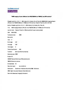
Fig. 1 - Definition sketch of the experimental setup (adapted from Chanson 2002) Measurements performed included flow rate, free surface elevation and total head. Additional information on the experiments are reported in Chanson (2002).
7010
33rd IAHR Congress: Water Engineering for a Sustainable Environment
EXPERIMENTAL FACILITIES The experimental results were obtained in an rectangular dropshaft scale model setup. The shaft was built in marine plywood and perspex with a vertical rectangular crosssection (L = 0.243 m, B = 0.246 m) with a drop in invert elevation of h = 0.548 m and a pool P = 0.322 m deep (Chanson 2002). The inflow and outflow channels were horizontal and rectangular, b1 = 0.161 m wide by D1 = 0.25 m tall, and b2 = 0.209 m wide by D2 = 0.097 m, respectively. The outflow channel was covered and ended with a free overfall (Fig. 1). NUMERICAL CODE Main features FLOW-3D® constitutes a general purpose CFD program (Flow Science 2008). The equations of motion are solved by the method of finite volume/finite differences in a Cartesian, staggered grid. In FLOW-3D® the domain can be constituted by single- or multi-block grids. Options for the incorporation of the full geometry into FLOW-3D® include (Flow Science 2008): i) a “solid modeler,” which allows for the use of general quadratic functions, ii) Computer-Aided-Design (CAD) files, or iii) topographic data. After both the geometry and the grid are defined, the Fractional Area-Volume Obstacle Representation (FAVOR™) method (Hirt and Sicilian 1985) automatically embeds the obstacles in the computational mesh by computing the area fractions on the cell faces, along with the volume fraction, opened to flow (Flow Science 2008). This makes grid generation and geometry definition separate tasks, allowing for independent modifications in each case. More information can be found in Flow Science (2008). General flow model The standard Reynolds-Averaged Navier-Stokes (RANS) equations are used in the theoretical model. The equations of motion can be written as follows: (1) ∇ ⋅ ρU = 0
( )
∂ρU + ∇ ⋅ ρ U ⊗ U = ∇ ⋅ Τ − pI + ρ b ∂t
(
with
[(
)
[
]
) ( ) ]− ρ u ⊗ u
Τ = ρµ ∇U + ∇U
T
(2)
(3)
where U is the turbulence averaged velocity vector, ρ the fluid density, p the average pressure, I the identity tensor, b indicates the body forces, u the vector of velocity fluctuations and µ is the dynamic viscosity. For this specific problem the body forces are composed only by gravity. The Reynolds stresses, last term of eq. (3), correlate the
7011
33rd IAHR Congress: Water Engineering for a Sustainable Environment
fluctuations of velocities and can be interpreted as a mechanism of momentum exchange between the mean flow and turbulence. This is an additional unknown term to the original Navier-Stokes equations. To close the problem, the Reynolds stresses are modeled using the eddy viscosity concept, and both the standard k-ε and k-ε RNG models were used to determine the turbulent kinetic energy (k) and the rate of dissipation of turbulent kinetic energy (ε) that contribute to the eddy viscosity. Location of the free surface The domain were the previous equations are valid is limited by the incoming flow in the inlet channel, the outgoing flow through the outlet channel, the solid boundary in the dropshaft, and the free surface. The latter is of particular relevance since it is “a priori” unknown in each time step. Free surface tracking in FLOW-3D® is accomplished using the VoF method (Hirt and Nichols 1981) in its “true” version, which requires three key elements to be implemented (Bombardelli et al. 2001). The "true" VoF solves the function of the fraction of fluid (F) through: ∂F + um ⋅ ∇ F = 0 (7) ∂t where u m the average velocity of the mixture. In this method, unlike in other methods appeared recently, the cells with gas are not considered and the flow is only computed in cells with liquid. So, the VoF method combines the advantages of minimum memory storage (only one variable, F, has to be recorded), reasonable computational cost and satisfactory accuracy. Additional boundary conditions In our problem, we specified pressure boundary conditions in both upstream and downstream boundaries. The values did not correspond to any experimental measurement since they were unknown for those sections. An additional symmetry boundary condition was added, as explained bellow. We checked that the boundary conditions selected did not produce spurious waves in the computational domain. We imposed null velocities normal to the dropshaft walls (impenetrability condition) and the usual wall functions for the turbulence statistics were employed. NUMERICAL MODEL IMPLEMENTATION
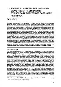
The geometry was generated using solid modeler incorporated in FLOW-3D®, based on the dimensions of the physical model. The inlet and outlet channels were extended relatively to the model, creating a "buffer" zone to prevent boundary conditions imposed to affect the results in the shaft. The domain was discretized using 3 main blocks: i) in the inlet channel; ii) in the shaft; and iii) in the outlet channel. Additional refined grid blocks were progressively nested into the previous to increase the resolution in key flow areas and evaluate mesh convergence (Fig. 2).
7012
33rd IAHR Congress: Water Engineering for a Sustainable Environment
Fig. 2 - Computational domain. Mesh refinement was performed until mesh-independent results were achieved. Runs A, B, and C were performed with a mesh of 547,448 cells while run D and E used 2,420,352 cells (see Table 1). In Run E it was used the k−ε RNG turbulence model was used and the results were identical to the runs with the standard k−ε turbulence model (Runs A, B, C and D). COMPARISON OF EXPERIMENTAL AND NUMERICAL RESULTS
The main results of the selected simulations are summarized in Table 1 and numerical results are present in Fig. 3. Detailed comments on the results are presented next. Flow rate (discharge) The first variable used to check the numerical results was the discharge. This was done by numerical integration of the velocity in several flow cross sections, using the trapezoidal rule. Relative differences among experimental and numerical values of discharge were less than 1.5%. This is a very satisfactory agreement if we consider that the difference between the measured discharge and the discharge calculated with the measured critical depth at the brink is higher (nearly 6%). The calculated discharge was obtained using the critical depth and using the following relation between the critical depth (dc) and the depth in the brink (db): db=0.725dc (the relation is close to Rouse's (1936) results and was found to be the best correlation in the case of the prototype measurements (Chanson 2007)).
7013
33rd IAHR Congress: Water Engineering for a Sustainable Environment
Water depths Water depths were computed in the brink by averaging the values across the entire cross sections perpendicular to the flow (y-z plane). In the shaft the section closest to the upstream wall was usedto determine the water depth, corresponding to the localization of the rulers used for the measurements in the experimental setup. The difference in accuracy between Runs A and B and the others is due to the introduction of the effect of wall roughness (considering ks=0.000152m) on the latter. This was found to improve the accuracy in terms of water depth in the brink but it was also observed to increase the difference for the water depth in the shaft. However, since the water depth in the shaft is highly unstable and was obtained by visual observation, it was considered more reliable the increase in accuracy of the results for the depth in the brink.
Table 1 - Summary of results. PARAMETER
RUN A RUN B Discharge [l/s] 5.51 5.48
RUN C
Computed 5.41 Calculated* 5.18 Measured 5.50 Difference (Comp./Meas.) 0.19% -0.34% -1.60% Difference (Calc./Mea.) -5.74% Water depth in the brink [mm] Computed 31.29 32.20 32.50 Measured 34.28 Difference -8.72% -6.07% -5.18% Water depth in the shaft [mm] Computed 424.20 429.00 415.40 Measured 439.95 Difference -3.58% -2.49% -5.58%
RUN D
RUN E
5.57
5.56
1.25%
1.14%
32.21
32.50
-6.04%
-5.18%
419.73
426.25
-4.60%
-3.11%
*Calculated using the critical depth (dc) determined from the depth brink (db) through the relation dc=db/0.725
CONCLUSION
This paper provides a first step in the numerical assessment of the hydraulic performance of plunge flow dropshafts. The runs developed in the paper show that the use of a k-ε model combined with the “true” VoF method allow for an adequate representation of the flow features. Further, the multi-block feature embedded in FLOW-3D®, which helps optimizing the mesh, was crucial for computational time savings.
7014
33rd IAHR Congress: Water Engineering for a Sustainable Environment
The results obtained in this work constitute a strong motivation to extend the models further, namely including an air-entrainment model to evaluate the effect of air in the energy dissipation.
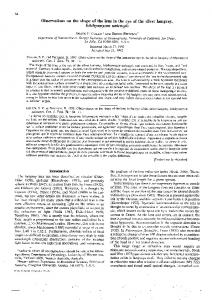
a)
b)
c) d) Fig. 2 - Numerical contours: a) turbulent kinetic energy dissipation; b) turbulent kinetic energy; c) velocity magnitude; d) pressure. Acknowledgments The first author was a Visiting Scholar at the University of California, Davis, during the months of September 2007 to February 2008, financially supported by ESTBarreiro/IPS. This support is gratefully acknowledged along with the support of FCT (Foundation for Science and Technology).
7015
33rd IAHR Congress: Water Engineering for a Sustainable Environment
REFERENCES Bombardelli, F.; García, M.; Caisley, M. (2000). “2-D and 3-D Numerical Simulation of Abrupt Transitions in Open-Channel Flows. Application to the design of canoe chutes.” Proc., 4th. Int. Conf. on Hydroinformatics, IAHR, Iowa City, IA, USA. Bombardelli, F.; Hirt, C.; García, M. (2001). "Computations of Curved Free Surface Water Flow on Spiral Concentrators." Disc., J. of Hydr. Eng., ASCE, 127(7), 629-631. Chanson, H. (2002). "An Experimental Study of Roman Dropshaft Operation: Hydraulics, Two-Phase Flow, Acoustics." Report No. CH50/02, University of Queensland, Department of Civil Engineering, Brisbane, Australia. Chanson, H. (2004). "Hydraulics of Rectangular Dropshafts." J. of Irrigation and Drainage Eng., ASCE, 130(6), 523-529. Chanson, H. (2007). "Air Entrainment Processes in a Full-Scale Rectangular Dropshaft at Large Flows." J. Hyd. Res., IAHR, 45(1), 43-53. Dahlin, W.; Wetzel, J.; Nesbeitt, K. (1982). "Hydraulic Modelling of Vertical Dropshaft Structures." Proc., Int. Conf. on Hydraulic Modelling of Civil Engineering Structures, Structures, BHRA Fluid Eng., Coventry, UK. EPA (1993). "Combined Sewer Overflow Control." Manual EPAJ625/R-93/007, U.S. Environmental Protection Agency (EPA), Office of Research and Development, Center for Environmental Research Information, Cincinnati, Ohio, USA. Flow Science (2008). "FLOW-3D User’s Manuals Version 9.2.1." Flow Science, Inc., Los Alamos, New Mexico, USA. Higgs, J. and Frizell, K.W. (2004). "Investigation of the Lake Plant Pump Station Lower Colorado River Authority." Hydraulic Laboratory Report HL-2004-02, Denver Technical Center, Bureau of Reclamation, United States Department of the Interior, Denver, Colorado. Hirt, C.; Nichols, B. (1981). "Volume of Fluid (VoF) Method for the Dynamics of Free Boundaries." J. of Comp. Physics, 39, 201-225. Hirt, C.; Sicilian, J. (1985). "A Porosity Technique for the Definition of Obstacles in Rectangular Cell Meshes." Proc., Fourth Int. Conf. Ship Hydro., National Academy of Science, Washington, DC, USA. Jalil, A.; Rajaratnam, N. (2005). "An Experimental Study of Plunging Flow in Vertical Dropshafts." 17th Canadian Hydrotechnical Conference, Edmonton, Alberta, Canada. Rajaratnam, N.; Mainali, A.; Hsung, C. (1997). "Observations on Flow in Vertical Dropshafts in Urban Drainage Systems." J. Env. Eng., ASCE, 123(5), 486–491. Rouse, H. (1936). “Discharge Characteristics of the Free Overfall.” Civil Engineering 6, 257. Williamson, S. (2001). "Drop Structure Design for Wastewater and Stormwater Collection Systems." Parsons Brinckerhoff, Monograph 14, New York, USA. Savage, B. M. and Johnson, M. C. (2001). “Flow over Ogee Spillway: Physical and Numerical Model Case Study.” J. of Hydr. Eng., ASCE, 127(8), 640-649.
7016