Kirk, Paul Keller, Mark Meyer, Mika Nyström, Niles Pierce, Burak Aksoylu, Michael. Holst, Jason Hickey, Ian Buck, Mark Harris and all the speakers and students ...
http://multires.caltech.edu/pubs/GPUSim.pdf (submitted for publication)
The GPU as Numerical Simulation Engine Jeff Bolz
Ian Farmer
Eitan Grinspun Caltech
Abstract
ger based fragment processing hardware. Examples include simulation of boiling [Harris et al. 2002], fluids and steam [Li et al. 2003], non-linear diffusion [Strzodka and Rumpf 2001], and general purpose dense matrix multiplication [Larsen and McAllister 2001; Thompson et al. 2002]. Many of the severe technical limitations these authors had to deal with, such as low precision [Strzodka 2002; Harris 2002] and the need to express all operations as (fancy) texture compositing operations, have fallen away: significant fragment programs with floating point data types and broad access to memory can now be written. Many applications in graphics and scientific computing could benefit from off-loading some or all of their numerical computations to the GPU, freeing the CPU to attend to other tasks. While there is a multitude of such applications and algorithms there are a few computational kernels which appear very frequently.
Many computer graphics applications require high-intensity numerical simulation. The question arises whether such computations can be performed efficiently on the GPU, which has emerged as a full function streaming processor with high floating point performance. We show in this paper that this is indeed the case using two basic, broadly useful, computational kernels as examples. The first is a sparse matrix conjugate gradient solver and the second a regular-grid multigrid solver. Many realtime applications ranging from mesh smoothing and parameterization to fluid solvers and solid mechanics can greatly benefit from these as we demonstrate with a prototype implementation on NVIDIA’s GeForce FX, using geometric flow and fluid simulation as application examples. CR Categories: I.3.1 [Computer Graphics]: Hardware Architecture—Graphics processors; G.1.3 [Numerical Analysis]: Numerical Linear Algebra—Sparse, structured, and very large systems (direct and iterative methods); G.1.8 [Numerical Analysis]: Partial Differential Equations—Multigrid and Multilevel Methods;
Contributions In this paper we describe the mapping of two fundamental computational kernels onto the GPU: a conjugate gradient solver [Shewchuck 1994] for sparse, unstructured matrices and a multigrid solver for regular grids [Briggs et al. 2000]. Both are workhorses of physical modeling and optimization applications and we demonstrate excellent performance on GeForce FX hardware in realistic challenge applications. We use the fragment shader stage exclusively for our purposes since it is the highest performance part of the programmable pipeline and, more importantly, allows for random read access to memory. The need for a sparse matrix solver arises in many simulations involving discretization of linear and non-linear PDEs [Hughes 1987]. For example, finite element modeling of elasticity [M¨uller et al. 2002], computation of conformal parameterizations [Desbrun et al. 2002], and the discretization of higher order shape optimization operators [Kobbelt et al. 1998]. A conjugate gradient solver is appropriate whenever the linear system is symmetric positive definite (SPD)1 . The main challenges in building such solvers on the GPU are the construction of (1) data structures for sparse matrices, (2) data parallel algorithms for sparse matrix vector multiplies, and (3) reduction operators for vector norm computations. With data laid out in texture memory, and fragment program execution—for a given group of fragments—having identical control flow, an efficient implementation requires the solution of a texture packing optimization problem. We present efficient solutions to these challenges and collect performance data for our solver in a geometric flow application [Desbrun et al. 1999]. Because of the non-linear nature of the mean curvature motion PDE, the linear system has to be recomputed at each time step. Our data structures support computation of the matrix entries on the GPU as well, making this algorithm well suited for both linear and non-linear PDEs on unstructured meshes. The above examples use unstructured meshes which require a non-trivial mapping of sparse data structures onto single-instruction multiple-data (SIMD) hardware [Blelloch 1990]. In many other settings regular grids may be preferred [Kass and Miller 1990; Stam 1999]. Such grids map more naturally onto the GPU hardware as they are akin to pixel (2D) or voxel (3D) structures, inviting different and more efficient implementations. The latter requires good preconditioning of the linear systems that arise when, e.g.,
Keywords: GPU Computing, Numerical Simulation, Conjugate Gradient, Multigrid, Mesh Smoothing, Fluid Simulation, Navier-Stokes
1
Peter Schr¨oder
Introduction
High performance graphics processing units (GPUs) such as the current ATI Radeon 9700 [ATI 2002] and GeForce FX [nVidia 2002] (among others) expose a flexible programming interface for their powerful floating point hardware. Because of their highly parallel nature, GPUs can already outperform CPUs and this disparity in performance is expected to widen further in the future [Semiconductor Industry Association 2002; Khailany et al. 2003]. These developments make GPUs serious contenders as high performance computational engines for floating point intensive applications. Aside from their utility in their current form, these chips also represent the first commercially successful examples of a class of future computing architectures which may be the key to high performance, cost effective super computers [Khailany et al. 2001; Owens et al. 2002]. Understanding the issues in mapping a variety of fundamental algorithms to this new computing paradigm thus promises to have many pay-offs. So far the computational resources of GPUs have been applied mostly to traditional graphics problems, enhancing, for example, the shading models and effects applied at the pixel level [Olano 2002]. That current generation GPUs are capable of far more general computation was demonstrated by Purcell and coworkers [2002] and Carr et al. [2002] who built ray tracing engines using on the GPU. Employing graphics hardware for purposes it was not designed for has a long tradition [Lengyel et al. 1990; Hoff et al. 1999], including early uses for numerical computing in the context of radiosity [Cohen et al. 1988; Keller 1997]. Many of these algorithms were based on rendering suitably chosen geometry with appropriate “colors” (e.g., object ID tags), followed by readback from the framebuffer. With the arrival of programmable vertex and fragment units [Lindholm et al. 2001] the available repertoire increased significantly. The new vertex programs allowed for floating point computations, but to this day they do not provide access to memory (“textures”). Consequently most of the recent efforts at mapping numerical algorithms onto GPUs have focused on using inte-
1 Non-symmetric and indefinite systems require closely related algorithms which use the same building blocks [Barrett et al. 1994].
1
the Laplace operator is discretized. In these settings the condition number of the matrix grows quadratically in the number of variables. This leads to quadratic running times for iterative solvers even though the matrices are still sparse. Multigrid solvers and preconditioners [Hackbusch 1985] address this problem, leading to linear time solvers independent of the grid spacing. We present an implementation of multigrid on the GPU. The resulting solver efficiently solves a variety of elliptic PDEs (Laplace, Bi-Laplace, Helmholtz, Poisson, etc.), which appear in many applications. In the graphics context such solvers were used, for example, for the construction of subdivision surfaces by Diewald and co-workers [2002]. The main challenge in performing this computation entirely on the GPU is the construction of the coarser-level system matrices given only a knowledge of the finestlevel discretization and the prolongation (subdivision) operators. In particular the computation must be structured to avoid scatter operations which are typical of CPU implementations. For performance evaluation of our multigrid implementation, we have implemented a Navier-Stokes fluid solver [Stam 1999], which requires (among other steps) a Poisson solver with Neumann boundary conditions.
3
Solvers for Unstructured Grids
Many algorithms for physical simulation or optimization on unstructured meshes use (multi-)linear finite elements or mass-spring systems. The degrees of freedom (DOFs), such as position, velocity, temperature, etc., are associated with vertices of a 2D (triangle, quadrilateral) or 3D (tetrahedral, hexahedral) mesh. The sparse linear systems that arise relate a given DOF to the DOFs in the incident elements. Our solver is ideally suited for these sparse linear systems. For concreteness we assume a triangle mesh with linear finite elements. Let the integers i = 1, . . . , n denote the vertices V of a 2manifold triangle mesh (with boundary), with edges E = {eij }. Denote the set of vertices in the 1-ring neighborhood of vertex i as N (i) = {j|eij ∈ E} and a (generic) DOF associated with vertex i as xi . Example DOFs include 3D position xi := (x, y, z)i or texture coordinates xi := (s, t)i . With this notation we get a set of n equations Ax = f X ∀i = 1, . . . , n : aii xi + aij xj = fi (1) j∈N (i)
2
Setup
We view the fragment shader of a modern GPU as a stream processor [Khailany et al. 2001]. The processor executes the same kernel (fragment program) to produce each element (rasterized pixel) of an output stream (group of rasterized primitives). The output stream is saved (texture memory) and used as input (via texture fetches) for downstream kernels. Our design maps the data structures and algorithms of our solvers into streams (textures) and kernels (shaders) respectively. The design was strongly motivated by three salient features of GeForce FX hardware: (1) inexpensive gather operations, (2) lack of a scatter operation, and (3) SIMD semantics. Together, these three features characterize our abstract streaming model: Gather Operation The processor provides random access memory fetch (“gather”) instructions into saved streams. The latency of the random memory access is hidden so long as the bandwidth is limited. Absent Scatter Operation Each run through the kernel produces exactly one output element. There are no random access memory write operations. Together the gather and absence of scatter dictate a many-to-one relationship between elements of input streams and a single element in the output stream. SIMD Semantics The GPU has two SIMD characteristics: (1) the same kernel is executed over all elements of a stream, and (2) processor instructions operate on wide data types, i.e., tuples of floating point values. Items (1) and (2) affected our approach to conjugate gradient and multigrid respectively. Notes Having no latency is very beneficial since linear algebra algorithms are inherently bandwidth intensive. The basic primitive is to take the inner product of two vectors. Being able to perform unconstrained reads from memory allows more freedom in choosing the data structures. Lack of scatter forces the stream kernels to be organized into groups. Each virtual processor can read other memory, but only write its own output. This fits well with many linear algebra operations, but not all. Applying the adjoint of an operator is most commonly formulated as a scatter operation. SIMD item (1) necessitated a packing problem in the conjugate gradient code in order to minimize the batch quantization penalty (see Section 3.3.1). SIMD item (2), wide data types, motivated us to use domain decomposition in the multigrid solver.
where the fi encode the right hand side and possibly boundary conditions, depending on the original problem setup. We assume here that the linear system is SPD (consequently aij = aji ). This allows us to use a conjugate gradient solver to find a solution to Equation (1). Both assumptions can be relaxed by going to more general solvers such as BiCG and GMRES [Barrett et al. 1994] which require the same fundamental computational primitives. Note that some of these solvers need access to an explicit representation of AT . For later use we sort the individual equations of the system (1) according to the number of non-zero off-diagonal coefficients aij . These can range from 0 to n − 1, but are six on average for a single closed triangle mesh. Let ik , 0 ≤ k < n denote the number of equations with k non-zero entries. These then occupy ik contiguous P rows starting with row index ( k−1 l=1 il ) + 1.
3.1
Example Systems
Many computer graphics settings give rise to linear systems with the structure of Equation (1). We consider three examples of increasing complexity: trivial coefficients, geometry dependent, but fixed coefficients, and a non-linear problem. Mesh Editing Kobbelt and co-workers [1998] performed interactive mesh editing with the operator A2 where aii = |N (i)| and aij = −1 iff j ∈ N (i), solving for point positions (x, y, z)i associated to each vertex. Note that the matrix coefficients depend only on the topologic structure of the mesh. Parameterization Desbrun and co-workers [2002] computed discrete conformal parameterizations setting aij = −(cot(αij ) + P cot(βij )), aii = − j∈N (i) aij and solved for texture coordinates (s, t)i at every vertex. Here βij and αij are the angles in 3-space opposite the edge eij . In this case the entries of the matrix depend on the input geometry, but are fixed for the duration of the solution process. Geometric Flow A closely related but non-linear problem is that of mean curvature flow [Desbrun et al. 1999]. In that setting the point positions xi (t) of the vertices are functions of time and undergo an evolution according to ∂t xi (t) = −λi (t)Hi (t)~ni (t), where Hi (t)~ni (t) denotes the mean curvature normal at vertex i and time t and λi (t) is the speed function. For simplicity we assume that λi does not depend on time. This equation is typically linearized through a semi-implicit discretization using a backward difference in time ∆t = t(k+1) − t(k) for the left hand side and the
a single element
state of the mesh at the beginning of a time step for the approximation of Hi (t)~ni (t). Note that this requires recomputation of A(k) (k) (k) (k) at every time step. We have aij = −λ∆t(cot(αij ) + cot(βij )) P (k) (k) (k) (k) and aii = 4Ai − j∈N (i) aij with Ai the area of the trian-
J+ J
X - vertex positions
Notes In the data dependent examples above a given non-zero entry in the matrix depends on all the data associated with the two triangles incident to a given edge (the diagonal term being a simple function of the sum of all off-diagonal terms). This is typical of finite element techniques over triangulations with a similar statement applying to tetrahedralizations. We will exploit this observation later when considering the construction of matrix entries on the GPU.
Conjugate Gradient Solver
Implementation of a conjugate gradient solver requires only a few non-trivial functions [Shewchuck 1994, p. 50]: sparse matrixvector multiply and vector inner-product. For the BiCG method the only additional function needed is application of the transpose of the sparse matrix to a vector. The sparse matrix-vector multiply requires a suitable sparse matrix data structure and an associated fragment program to execute the multiply. The inner product computation requires a sum-reduction.
I
one kernel
gles at time t(k) incident to vertex i.
3.2
J-
(J,I,J+,J-) R - pointers to segments
Ai - diagonal matrix entries
Aj - off-diagonal matrix entries
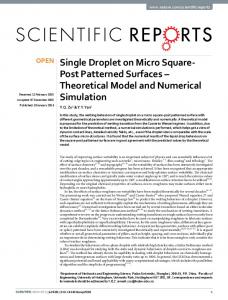
Figure 1: Given a row i, which is in effect an address in X x , the inner product of sparse matrix row i and vector X x is performed as follows. The address i provides access to aii in Axi and through Rx to the beginning address of the sequence of off-diagonal non-zero matrix entries stored in Aaj . Iterating along this segment retrieves aij . The corresponding xj locations are accessed via indirection through J a . inner product kernel becomes j
=
Rx [i]
Y x [i]
=
Axi [i] ∗ X x [i] +
ki −1
X
Aaj [j + c] ∗ X x [J a [j + c]],
c=0
3.2.1
Sparse Matrix Vector Multiply
Principle To understand the particular layout for the unknown variables consider the implementation of the sparse matrix vector multiply. The basic computational kernel of this operation—to be executed by a fragment program—is the inner product between a given row of the matrix and the vector. Fragment programs must execute in SIMD style lockstep. This can be achieved by “rendering” all rows with an equal number of non-zero entries as a group, i.e., as one rectangle of the appropriate size. Each rectangle is bound to a fragment program designed for the appropriate number of non-zero entries. A fragment program needs to be able to access the appropriate non-zero entries in a given row and the associated elements of the vector. Each of these—the matrix A and vector x—are stored in textures requiring appropriate indirections (see Figure 1 for a graphic depiction of the layouts and indirections). Since x is read as well as written it must be laid out with particular care. To achieve good performance, the layout needs to be optimized to limit the waste of space and achieve a certain granularity to assure high throughput on the GPU. We will discuss this optimization problem, and the factors which control it, in Section 3.3. Details Let the vector of unknowns x be laid out in a texture X x as a set of rectangles according to the number of non-zero offdiagonal entries ki in a given row i (Figure 1). The superscript denotes the particular layout. The sparse matrix A is stored in two textures. The diagonal entries Axi are laid out the same as X x . The off-diagonal, non-zero entries are packed into consecutive segments of a new texture Aaj (a layout familiar from SIMD programming [Blelloch 1990]). The superscript again denotes the particular layout of this texture. The index of the beginning of each row segment is stored in an indirection texture Rx . Finally we have a texture J a with each entry holding the address in X x of the corresponding element. Letting i be the address of a given element in X x the sparse row vector
where Y x denotes some destination texture with the same layout as X x . By rendering appropriate rectangles into Y x —each bound to a fragment program with the appropriate upper bound on the above sum—using texture coordinates i which are the pixel addresses in Y x , we can perform the desired sparse matrix vector product Ax (see also Figure 1). Notes The indirection textures Rx and J a depend only on the mesh connectivity and can be initialized at the time a mesh is first constructed. The separate storage for Axi and Aaj turns out to be advantageous for diagonal preconditioning—division of the residual vector by the diagonal entries—as well as the generally different methods by which diagonal and off-diagonal entries are computed in the first place (see Section 3.2.2). With the setup we have given for sparse matrix vector product, transpose products require an explicit representation of AT . In case that A and AT have differing numbers of non-zero entries per row the maximum of the two must be chosen for the initial sorting order. 3.2.2
Computing Matrix Entries
Principle In the case that the entries of A depend on x we require two additional kernels. One to update Axi and another for Aaj . In traditional FEM codes this is typically done by an iteration over all elements computing local stiffness matrices, i.e., the linear operator relating all DOFs incident on the element. These local stiffness matrices are then accumulated into a global stiffness matrix. Unfortunately this requires a scatter operation which is not yet available on current generation GPUs. Instead we must compute the nonzero entries directly. We have two types of non-zero entries, those associated with vertices Axi and edges Aaj . We begin with the latter. Details The coefficient associated with a given edge is controlled by the two incident triangles, which in turn are completely described by their incident vertices—a total of four. Consider for example the coefficients which arise in the geometric flow problem (Section 3.1). Aside from J a this requires I a , J+a , and J−a
(see Figure 1). With these in place all we need is to “render” Aaj with texture coordinates j and the fragment program cot(a, b, c)
=
xi xj−
= =
(a − b) · (c − b) k(a − b) × (c − b)k X x [I a [j]] xj = X x [J a [j]] X x [J−a [j]] xj+ = X x [J+a [j]]
Aaj [j]
=
−λ∆t(cot(xj , xj− , xi ) + cot(xi , xj+ , xj )).
Axi
The are computed with the same overall structure as a sparse matrix vector multiply and the following fragment program
texels. Such unused texels occur since the objects on which we perform reductions have the layout of X x with some unused texels in individual rectangles as well as in the overall texture.
3.3
Packing
Recall that X x textures will be read and written by fragment programs. To get good performance out of writing operations we must optimize the layout of X x variables. These come in groups of size ik according to the number k of non-zero off-diagonal entries in A. We first discuss the model we assume for the resulting optimization.
ki −1
Axi [i] =
X
4A(xi , xj− , xj ) − Aaj [Rx [i] + c].
c=0
Boundaries In geometric flow one can either fix vertices on the mesh boundaries (as we do in the examples), or let them flow under a length minimizing curvature flow. The latter requires its own tridiagonal linear system, which can be implemented on the GPU as well. Fixed boundaries effectively remove some vertices from the list of degrees of freedom, though they still enter into the matrix coefficient computations. So while they are stored in X x , they are not assigned to a rectangle with a fragment program: There are no corresponding rows in the matrix. Notes For tetrahedral meshes the same overall structure applies with one important difference. The number of tets incident on an edge is not bounded. Hence one needs J a , I a and a variable length set of indirections for the ring of vertices surrounding an edge. This can be laid out in a fashion similar to the structure of Aaj . Sometimes the computation of Axi requires direct access to the 1-ring of neighbors. These are available through X x [i] and X x [Rx [i] + c]. If ordering, for example counterclockwise, is important, the entries of Rx must be constructed accordingly. 3.2.3
Reduction Operators
Reduction operators apply a binary associative2 operator to all elements of a vector returning the result r = v1 ◦ v2 ◦ · · · ◦ vn . The operator is not required to be commutative, e.g., the vector could contain matrices and ◦ may be matrix multiplication. We require only sum-reduction and will take advantage of the fact that addition is commutative, i.e., we will not require any particular order. This allows us to perform reduction for vectors, such as X x , indexed by two indices without regard to the order3 . To compute the inner product of two vectors p = x · y, we need a sum-reduction on the pairwise products. This operation appears in a number of places in the conjugate gradient algorithm. Let X x be a vector holding elements to be sum-reduced. The reduction is achieved by rendering a quadrilateral with half the dimension along either axis, summing four elements. Applying this process repeatedly, akin to a mip map pyramid, we will finally render a single pixel quadrilateral containing the sum-reduction result. Notes If the dimensions of X x are not powers of two the reduction must deal with odd length dimensions. One could always test whether texels are out of bounds before including them in the reduction. Or, separate fragment programs can be run on the boundaries. The batch quantization makes this unattractive for smaller textures. Texels that do not correspond to actual data elements can be reduced so long as they contain the identity of the reduction operator. Thus to initialize a sum-reduction we place zeros in unused 2 Real addition associates, floating point addition does not. We will ignore this distinction. 3 The traditional way of dealing with higher-D is to perform reductions in each dimension in order [Blelloch 1990; The C* Team 1993].
3.3.1
GPU Streaming Model
So far we have adopted an abstract streaming model. We must now specialize to consider characteristics of a GPU streaming model: SIMD GPUs execute fragment programs in SIMD fashion. Let p be the number of parallel pipelines; then every instruction operates on a tuple of p neighboring texels. For peak performance we must make useful work of every texel in the tuple. Triangle Rasterization GPUs are optimized for rendering triangles. We assume that axis aligned rectangles are rendered as a pair of axis aligned right triangles. In rendering each right triangle there is wasted work along the hypotenuse since parts of every tuple will lie outside the triangle. In rendering a rectangle of tuple dimension w × h, tuples along the diagonal tend to be rasterized twice. The total number of tuples sent to the fragment stage is therefore approximately wh + max(w, h). For peak performance we must minimize the wasted work max(w, h) along the diagonal. Round-Robin Pipelining of Texture Memory Access A fundamental issue in streaming architectures is hiding the memory-access latency [Arvind and Iannucci 1987]. To that end, streaming processors are typically multi-threaded (one early example was the HEP computer [Leiserson et al. 1993]. In a multi-threaded architecture, q independent stream records are processed in an interleaved manner. In this approach the program with instructions I1 , I2 , I3 , . . . is executed over records R1 . . . Rq using the sequential ordering I1 (R1 ), I1 (R2 ), . . . , I1 (Rq ), I2 (R1 ), . . . , I2 (Rq ), I3 (R1 ) . . . . Note that q − 1 cycles elapse between potentially data-dependent instructions. The designer must choose q large enough to hide memory latency and trade this off against the required additional chip area. A key consequence is that the fragment units process batches of q tuples. For peak performance we must ensure that all the q tuples provide useful work.
0
200
400
600
800
1000
1200
Figure 2: Normalized plot showing time vs. rectangle area as observed on the GeForce FX. The rectangle area does not include the wasted pixels along the diagonal. The value q × p = 512 is clearly noticeable, although the area is actually just below 500 because of the diagonal waste. 3.3.2
Optimization
Taking into consideration our above model we pack an output stream into a sequence of identical rectangles. Such a packing is
trivial to precompute. The dimensions of the rectangle are hardware dependent and are suitably chosen. This can be done through simple experiments which reveal estimates of pq (see Figure 2). We assume that triangles have startup costs which are small enough that they are not noticeable if a triangle contains a (small) minimum number of tuples. Effects due to pq are assumed to be noticeable only when changing fragment programs. Dimensions A rectangle of dimensions w and h produces wh+ max(w, h) tuples. With the fragment stage processing batches of q tuples, an optimal rectangle maximizes the amount of useful work wh subject to the constraint wh+max(w, h) ≤ zq for some integer z. This defines a family of optimal rectangles corresponding to the number z = 1, 2, . . .. We choose a single solution from this family since this leads to a trivial rectangle layout algorithm. Stream Packing Given an output stream of N texels it can be packed into ddN/pe/(wh)e rectangles which results in dN/pe mod wh wasted “filler” tuples. To minimize the wasted work, we choose z = 1 which gives the smallest rectangle thus providing the finest granularity in packing the stream. The inefficiency for z = 1 as compared to z � 1 is negligible (< 10%) and well worth the resulting trivial layout problem. On the GeForce FX we found that a rectangle of dimensions 26 × 18 pixels gives the lowest proportion of wasted pixels. Rectangle Layout The only parameter to the layout problem is the number of rectangles to lay out. We can compute off-line the optimal layout, i.e., determine the best texture dimensions s and t as a function of the number of rectangles to lay out. A simple lookup at runtime is thus sufficient to achieve a good layout. Multiple Programs For the sparse matrix problem we have multiple streams Sk each with ik records to be processed by a program Pk . Note that program Pk can process sparse matrix rows with k or fewer non-zero off-diagonals if we allow zero padding. This property is useful in meshes with few vertices of a particular valence. The underlying assumption is that a partially filled batch of q tuples costs exactly the same as a fully filled batch. We adopt the following greedy solution. Lay out the streams in decreasing order of program cost k = n − 1, . . . , 0 and assign them to rectangles R1 , R2 , . . ., filling each rectangle to capacity. Now use the least expensive program Pk valid for all elements of Rj . Notes All the layout issues can be solved at the time the mesh is created. The entries in Aaj , i.e., the length of each row segment, must be appropriately padded however. The corresponding entries in J a should point to a constant address in X x which contains zero. The constant address helps avoid unnecessary burden on the texture cache. The value zero assures that garbage values placed in Aaj in the padded slots during matrix recomputation do not matter.
3.4
Performance
We have implemented all of the components of a general conjugate gradient solver, as well as the specific matrices for geometric flow, including their recomputation for each smoothing step. The most performance critical functions are the matrix-vector multiply and the sum-reduction. We performed timing tests on a GeForce FX board using a mesh with 37k vertices (the scanner data in Figure 3). The matrix-vector multiply takes 33 instructions on an average row of the matrix (seven non-zero elements). At 500 MHz and 37k vertices, one could theoretically perform over 400 matrix multiplies. In practice, we observe about half this peak. A reduction, as described, requires seven instructions (four fetches and three adds) per destination fragment per pass. For a 200 × 200 layout to be reduced to 100 × 100, the cost of one pass of the reduction should be 70k instructions. Doing this at all levels
Figure 3: On the upper left a cube with normal noise and to its right a smoothed version (for the movie see http://multires.caltech.edu/pubs/CubeSmoothing.mpg). On the lower left a scanned mesh contaminated with acquisition noise. It is denoised through geometric flow (for the movie see http://multires.caltech.edu/pubs/ScanSmoothing.mpg). Note that this mesh has complicated boundaries. of the hierarchy, increases this by a factor of 4/3. Theoretically, the sum reduction can be performed over 5000 times per second. In practice our code executes at roughly 2000 reductions per second. The relative time between matrix-vector multiply and sumreduction includes a factor of two due to the different number of registers required (four respectively two). This is consistent with the notion of virtualizing hardware resources. The CG inner loop does a single matrix multiply and two reductions, as well as some significantly less costly operations that can be considered free. This entire loop can be performed about 160 times per second. The CG solver typically only needs a few iterations— e.g., five—for each smoothing step, so an entire smoothing step can be performed in less than 1/30 th of a second. Note Current drivers have a performance penalty—revalidation of the OpenGL pipeline state—during pbuffer switches, which is unnecessary for our computations. At present only about 200 pbuffer switches per second are possible, severely limiting performance. This limitation is expected to be removed in the near future. The movies were produced from screen dumps running on actual hardware, in effect simulating a setting with the pbuffer switch penalty removed.
4
Solvers for Regular Grids
We now turn to solvers for second order elliptic PDEs. For certain applications these are best discretized on a regular grid. Fluid solvers are a typical representative from the kinds of physical models which give rise to these systems [Stam 1999] (see also Section 4.1). Here we consider the Helmholtz equation with Dirichlet and/or
Neumann boundary conditions on the unit square, Ω = [0, 1]2 −∇2 u(x) + σu(x) u(x) ~n · ∇u(x)
= = =
Notes To keep the multigrid solver simple we do not work with staggered grids [Fedkiw et al. 2001], but instead colocate pressure and velocity fields as was done by Stam [1999]. The domain is discretized into (N + 1) × (N + 1) uniformly spaced samples distance h = 1/N apart with pressure and velocity variables
g(x) x ∈ Ω ⊂ R2 uD (x) x ∈ ∂Ω or uN (x) x ∈ ∂Ω,
where ~n denotes the outward pointing normal on the boundary of the domain whenever this quantity is well defined. To solve this PDE we may choose a variety of discretizations (finite elements, finite volumes, finite differences), some of which may be more suitable for particular settings. For purposes of exposition we choose a finite difference discretization and recall here only briefly the associated discretization. The Laplace operator ∇2 uses centered second differences in the interior. For Dirichlet boundaries only interior equations are required. We may assume that the boundary values vanish uniformly by subtracting the boundary conditions. The vector of unknowns still contains the boundary “unknowns,” i.e., zeros, to avoid having to use special stencils near the boundary. In the case of Neumann conditions the boundary stencils follow from the boundary conditions themselves, i.e., the centered difference at the boundary should equal the prescribed value. For non-zero Neumann conditions this creates an appropriate contribution to the right hand side. To ensure that the linear system for the Neumann problem is symmetric boundary equations must be divided by two (and corner equations by four). Later on we will also need to compute the divergence of a field (Equation (3) below) for which one can use centered differences at interior points and appropriate one-sided differences at the boundaries. Linear System Whether finite differences, volumes, or elements are used, we end up having to solve a linear system Ah uh = bh in (N + 1) × (N + 1) variables, not all of which are free. The linear operator Ah acting on the 2D grid uh may be described by a set of stencils, with possibly varying entries, each of size no larger than 3 × 3 (2 × 3 at the boundary, 2 × 2 at the corner). Care is required in the Neumann case as it has a non-trivial null space (see [Briggs et al. 2000, pp. 113–119]). For our implementation we used the discretizations as described above.
4.1
Incompressible Navier-Stokes
As a challenge problem we implemented Stam’s solver for the incompressible viscous Navier-Stokes equations [1999]. The fluid is governed by a velocity field u which satisfies ∇·u = 0 ρ
∂u = −(u · ∇)u + ν∇2 u + ρb ∂t
(ρI − ν∆t∇2 )u∗ = ρu(k) + ∆t(ρb(k) − (u(k) · ∇)u(k) ) (2) u
(k+1)
ui,j = (ux , uy )i,j
i, j = 0, . . . , N
In case periodic boundary conditions are used the associated indices are to be understood modulo N , i.e., 0 ≡ N . 4.1.1
Advection Step
Following Stam [1999] we trace integral curves back in time to compute the advected velocity field uadv = (u · ∇)u uadv i,j = C(u, −∆tu)i,j . where we used a simple first order integrator (higher order integrators can be defined as well). The operator C returns a field which is interpolated (typically bilinear) from its first argument field using offset vectors given by the second argument field. Offsets that leave the domain are properly clamped to the domain boundary. Note that boundary conditions are automatically preserved by the interpolation operation.
4.2
Multigrid
In this section we assume that N = 2j for some j > 5. Systems with fewer variables can be solved sufficiently fast with a diagonally preconditioned conjugate gradient algorithm. To simplify the exposition we will only describe a simple V-cycle with either Neumann or Dirichlet boundary conditions. Mixed boundaries are possible as well, but not required by our examples. The basic ingredients required for multigrid are a simple relaxation scheme—we will use weighted Jacobi—and interpolation and projection operators. The latter are used to build the system matrices at coarser levels as well as to propagate residual and correction vectors between levels of resolution. For an excellent introduction to the multigrid method we recommend the text by Briggs and co-workers [2000]. To build the coarser matrices we need an interpolation operator S from coarse to fine and a projection operator P from fine to coarse. For S we choose bilinear subdivision and for P full weighting, i.e., P = 1/4ST , resulting in a coarser level system matrix A2h = PAh S,
where b denotes external body force, ν the viscous drag, and the ρ is the fluid density (we will assume it to be unity). Using a semiimplicit time discretization as well as a projection step to ensure a divergence free vector field, the update from time t(k) to t(k+1) = t(k) + ∆t proceeds as
∇2 p = (ρ/∆t)∇·u∗
pi,j
(3)
∗
= u − (∆t/ρ)∇p ,
where p is a pressure field which may be discarded at the end of the time step. The first equation solves for a new velocity field using a Helmholtz solver with zero Dirichlet boundary conditions, while the second equation uses a Poisson solver with zero Neumann boundary conditions. Implementing this time stepping requires two non-trivial functions. One for the advection step and the other for an elliptic PDE solver.
and so on recursively to some coarsest level. With these in place the V-cycle multigrid algorithm can be stated as uh ← V-Cycle(η1 , η2 , vh , bh ) If ( CoarsestQ ( h ) ) Return uh ← Solve(Ah , vh , bh ) Else vh ← Relax(η1 , vh , bh ) // pre-smooth b2h ← P(bh − Ah vh ) // project residual v2h ← V-Cycle(η1 , η2 , 02h , b2h ) // recurse vh ← vh + Sv2h // interpolate & correct Return uh ← Relax(η2 , vh , bh ) // post-smooth Iteration towards solution at the finest level is performed by starting with an initial guess vh and the right hand side bh and improving it through repeated application of the V-cycle algorithm. The parameters η1 and η2 control the number of pre- and post-smoothing steps. Other variants such as µ-cycle and full multigrid are straightforward variations on the above code [Briggs et al. 2000]. For the smoother we choose the damped Jacobi iteration with ω = 2/3
uh ← Relax(η, vh , bh ) For ( i = 0; i < η; i = i + 1 ) r ← bh − Ah vh vh ← vh + ω(Ah )−1 ii r Return uh ← vh For simplicity we will use Jacobi iteration for the coarsest level solve as well. From the above pseudo code we see that we need the following non-trivial functions: (1) application of the interpolation operator S to a vector; (2) application of the projection operator P to a vector; (3) application of Ah to a vector; and (4) computation of A2h . Texture Layout Assuming a 2D domain, we lay out all data in 2D textures. Access into textures is described through multiindex notation i = (i0 , i1 ), with arithmetic understood in the vector sense. To iterate over neighbors, respectively entries in a stencil, we use index sets such as {0, 1}2 = {(0, 0), (0, 1), (1, 0), (1, 1)} using the standard definition of set product. Recall that Ah can be seen as a map from grid points to 3 × 3 stencils. We store the matrix as nine 2D textures Adh [i], d ∈ {−1, 0, 1}2 each a map from grid points i to the stencil entry indexed by d. Matrices A2h , A4h , etc. are similarly stored. To utilize all four channels in the floating point units, the quadrants of the domain are packed into a texture half the size in each dimension. This packing must group odd and even indexed nodes so that interpolation and projection operators are uniform. Since many computations require accessing neighbors, this packed format must have a border that contains duplicates of some nodes. These duplicates must be kept in sync during computation, issues well known from domain decomposition [Demmel 1997]. Interpolation Given a vector v2h stored in a 2D texture, interpolation to the finer level becomes X vh [i] = 1/4 v2h [b(i + d)/2c]. d∈{0,1}2
For Neumann conditions the boundaries get interpolated as any other point in the domain. For Dirichlet boundary conditions the boundary should not be interpolated, but we do so anyway. Since the Dirichlet boundary conditions always vanish, no harm is done and the implementation is simplified. Projection Since we are using full weighting, projection is performed via the adjoint of subdivision save for a division by four X v2h [i] = 1/4 Sd vh [2i + d] d∈{−1,0,1}2
where d indexes the stencil, S = 1/4{1, 2, 1, 2, 4, 2, 1, 2, 1} (using lexicographic order on d). This code applies at all points in the interior of the domain. On the boundary (i0 = 0, N/2 and/or i1 = 0, N/2) the above code is correct for Neumann boundary conditions with out of bounds accesses clamped to zero. For Dirichlet boundary conditions all boundary values of v2h must be set to zero explicitly. This is easily achieved by initializing to zero and “rendering” a rectangle covering only indices 1 . . . N/2 − 1. Matrix Vector Multiply Here stencil accesses to the matrix Ah must be mapped appropriately to index offsets in the vector uh X vh [i] = Adh [i]uh [i + d]. d∈{−1,0,1}2
For Dirichlet boundaries this code is executed only in the interior. For Neumann boundaries it is also executed on the boundary with out of bounds accesses clamped to zero.
Figure 4: An example of several time steps during a simulation run with particle advection used for visualization of the velocity field (for the movie see http://multires.caltech.edu/pubs/fluidflow.mpg). The inlet on the left has a high inward velocity (two grid spaces per timestep). This particular simulation was run with a domain size of 513 × 129. When fluid is pushed into the larger area, which is initially at rest, vortices are shed, a phenomenon clearly visible in the pattern of the particles. Composition of Stencils The most involved operation is the computation of coarser level stencils as the composition of operators S, Ah , and P each of which is given as a stencil. Formally we can express this as the triple operator composition (A2h ) = PAh S, which may be expanded in index notation as X Ad2h [i] = 1/4 Se Se+g−2d Agh [2i + e] e,g∈{−1,0,1}2
Stencils on the boundary only need to be computed for Neumann boundaries, in which case out of bounds accesses are clamped to zero. Performing the stencil composition correctly was one of the most subtle implementation issues in our algorithm. In the above expression we assume that out of bounds accesses on S are clamped to zero, easily achieved by creating a very small, suitably padded texture map for S. The sum could also be teased apart with careful analysis of which terms actually contribute to the sum. This not being a time critical part of the algorithm we refrained from that optimization.
4.3
Performance
We have implemented the fluid solver of Stam [1999] as a realistic application context for a multigrid solver. Following [Fedkiw et al. 2001] we did not perform diffusion (ν = 0) on the velocity variables. Consequently we used the multigrid solver only for the Neumman problem involved in the pressure computation (Equation 3). The most expensive operation in the multigrid V-cycle is the matrix-vector multiply, i.e., application of the stencil. The program has 27 instructions. On a 257 × 257 grid (stored as a 129 × 129 4-deep texture), this operation can be performed over 1750 times
per second at 500 MHz. The operation is proportionally cheaper on smaller grids, except that on very coarse grids there is a penalty due to the batch quantization. On a 17 × 17 fragment grid this penalty is almost 50%, at 33 × 33 it is 29%, and decreases as the grid gets larger. The interpolation and projection steps are applied once per level in the V-cycle algorithm. The interpolation kernel is 12 instructions long while projection takes 19. These kernels execute at 920 respectively 630 million instruction issues per second. We have found that a good choice of parameters is to have several Jacobi iterations per level, which decreases the performance impact of interpolation and projection. In general, the latter do not limit performance. The advection step is not performed on the packed velocity field because it is not possible to fetch four texels simultaneously. Performing the advection on 4 vertices in the same program would require at least 4 times the number of instructions, making the packed format useless in this case. In addition, since the hardware does not support bilinear filtering for floating point buffers, it must be coded explicitly. Since advection is performed only once per timestep, the costs associated with the unpacking, packing, and bilinear filtering are negligible. The number of pre- and post-smoothing iterations can be tweaked as necessary depending on the particular problem being solved. The system in Figure 4, with at times large divergence, still looks good with few iterations, e.g., four pre-smoothings and two post-smoothings. Neglecting pbuffer overhead, a single timestep with one multigrid V-cycle, using four pre-smoothing and two post-smoothing steps could be applied to a 513 × 513 grid in approximately 1/50 th of a second. For our simulations we used a grid of 513 × 129.
5
Conclusion
We have demonstrated a mapping of two widely applicable solvers to the GPU, and have provided solutions to many of the peculiarities that arise on this hardware. These design choices can be applied to other algorithms as well. Neglecting the unnecessary overhead of pbuffer switching, our implementation performs exceedingly well. Both applications would run in realtime for the given problem instances. The multigrid solver has enormous performance potential, and would be even more useful if it were applied to irregular grids. The issues involved in this deserve further study. A more straightforward extension would be application of the proposed sparse matrix CG algorithm to simulations involving tetrahedral meshes. The Cg language could provide an alternative implementation path, but it is not as well suited to scientific computing applications. For example, the concept of a pointer is meaningful for numerical applications, but not necessarily for graphics. The ability to “allocate” parts of a texture—similar to “processor allocation” [Blelloch 1990] in SIMD programming—would alleviate some of the tedium of packing. A specialized compiler that hides such distinctions would make this hardware more accessible to those less familiar with computer graphics. Performance could be boosted further if texture fetch instructions allowed additional offsets to be added to input coordinates. This could decrease the instruction count of the CG matrix multiply by as much as 20%. Finally, reduction operators would benefit greatly from a few globally writable registers. For example, a single accumulation register would allow a sum-reduction to be performed in a single pass. Limiting such registers to commutative operators would avoid troublesome order dependencies. Acknowledgment This work was supported in part by NSF (DMS-0220905, DMS-0138458, ACI-0219979), the DOE (W-7405-ENG-48/B341492), NVIDIA, the Center for Integrated Multiscale Modeling and Simulation, Alias|Wavefront, Pixar, and the Packard Foundation. Special thanks to Matt Papakipos, Nick Triantos, David
Kirk, Paul Keller, Mark Meyer, Mika Nystr¨om, Niles Pierce, Burak Aksoylu, Michael Holst, Jason Hickey, Ian Buck, Mark Harris and all the speakers and students in the “Hacking the GPU” class (Caltech, Fall 2002).
References A RVIND , AND I ANNUCCI , R. A. 1987. Two Fundamental Issues in Multiprocessing. In Proceedings of DFVLR - Conference 1987, “Parallel Processing in Science and Engineering’. ATI, 2002. Radeon 9700. http://www.ati.com/. BARRETT, R., B ERRY, M., C HAN , T. F., D EMMEL , J., D ONATO , J., D ONGARRA , J., E IJKHOUT, V., P OZO , R., ROMINE , C., AND DER VORST, H. V. 1994. Templates for the Solution of Linear Systems: Building Blocks for Iterative Methods, 2nd ed. SIAM. B LELLOCH , G. E. 1990. Vector Models for Data-Parallel Computing. MIT Press. B RIGGS , W. L., H ENSON , V. E., AND M C C ORMACK , S. F. 2000. A Multigrid Tutorial, 2nd ed. SIAM. C ARR , N. A., H ALL , J. D., AND H ART, J. C. 2002. The Ray Engine. In SIGGRAPH/Eurographics Workshop on Graphics Hardware. C OHEN , M. F., C HEN , S. E., WALLACE , J. R., AND G REENBERG , D. P. 1988. A Progressive Refinement Approach to Fast Radiosity Image Generation. Computer Graphics (Proceedings of SIGGRAPH) 22, 75–84. D EMMEL , J. W. 1997. Applied Numerical Linear Algebra. SIAM, Philadelphia, PA. ¨ D ESBRUN , M., M EYER , M., S CHR ODER , P., AND BARR , A. H. 1999. Implicit Fairing of Irregular Meshes Using Diffusion and Curvature Flow. In Proceedings of SIGGRAPH, 317–324. D ESBRUN , M., M EYER , M., AND A LLIEZ , P. 2002. Intrinsic Parameterizations of Surface Meshes. Computer Graphics Forum (Proceedings of Eurographics) 21, 3, 209–218. D IEWALD , U., M ORIGI , S., AND RUMPF, M. 2002. A Cascadic Geometric Filtering Approach to Subdivision. Comput. Aided Geom. Des. 19, 9, 675–694. F EDKIW, R., S TAM , J., AND J ENSEN , H. W. 2001. Visual Simulation of Smoke. In Proceedings of SIGGRAPH, 15–22. H ACKBUSCH , W. 1985. Multi-Grid Methods and Applications. Springer Verlag, Berlin. H ARRIS , M. J., C OOMBE , G., S CHEUERMANN , T., AND L ASTRA , A. 2002. Physically-Based Visual Simulation on Graphics Hardware. In SIGGRAPH/Eurographics Workshop on Graphics Hardware. H ARRIS , M. J. 2002. Analysis of Error in a CML Diffusion Operation. Tech. Rep. TR02-015, UNC Chapel Hill. H OFF , K. E., K EYSER , J., L IN , M., M ANOCHA , D., AND C ULVER , T. 1999. Fast Computation of Generalized Voronoi Diagrams Using Graphics Hardware. In Proceedings of SIGGRAPH, 277–286. H UGHES , T. J. R. 1987. The Finite Element Method: Linear Static and Dynamic Finite Element Analysis. Prentice-Hall. K ASS , M., AND M ILLER , G. 1990. Rapid, Stable Fluid Dynamics for Computer Graphics. Computer Graphics (Proceedings of SIGGRAPH) 24, 4, 49–57. K ELLER , A. 1997. Instant Radiosity. In Proceedings of SIGGRAPH, 49–56. K HAILANY, B., DALLY, W. J., R IXNER , S., K APASI , U. J., M ATTSON , P., NAMKOONG , J., OWENS , J. D., T OWLES , B., AND C HANG , A. 2001. Imagine: Media Processing with Streams. IEEE Micro 21, 2, 35–46. K HAILANY, B., DALLY, W. J., R IXNER , S., K APASI , U. J., OWENS , J. D., AND T OWLES , B. 2003. Exploring the VLSI Scalability of Stream Processors. In Proceedings of the Ninth Symposium on High Performance Computer Architecture. KOBBELT, L., C AMPAGNA , S., VORSATZ , J., AND S EIDEL , H.-P. 1998. Interactive Multi-Resolution Modeling on Arbitrary Meshes. In Proceedings of SIGGRAPH, 105–114. L ARSEN , E. S., AND M C A LLISTER , D. K. 2001. Fast Matrix Multiplies using Graphics Hardware. In Supercomputing. L EISERSON , C., ROSE , F., AND S AXE , J. 1993. Optimizing Synchronous Circuitry by Retiming. In Third Caltech Conference On VLSI. L ENGYEL , J., R EICHERT, M., D ONALD , B. R., AND G REENBERG , D. P. 1990. Real-Time Robot Motion Planning Using Rasterizing Computer Graphics Hardware. Computer Graphics (Proceedings of SIGGRAPH) 24, 327–335. L I , W., W EI , X., AND K AUFMAN , A. 2003. Implementing Lattice Boltzmann Comptuation on Graphics Hardware. The Visual Computer. To appear. L INDHOLM , E., K ILGARD , M. J., AND M ORETON , H. 2001. A User-Programmable Vertex Engine. In Proceedings of SIGGRAPH, 149–158. ¨ M ULLER , M., D ORSEY, J., M C M ILLAN , L., JAGNOW, R., AND C UTLER , B. 2002. Stable Real-Time Deformations. In ACM SIGGRAPH Symposium on Computer Animation, 49–54. N V IDIA , 2002. GeForce FX. http://www.nvidia.com/.
O LANO , M., Ed. 2002. Real-Time Shading Languages. Course Notes. ACM SIGGRAPH. OWENS , J. D., K HAILANY, B., T OWLES , B., AND DALLY, W. J. 2002. Comparing Reyes and OpenGL on a Stream Architecture. In SIGGRAPH/Eurographics Workshop on Graphics Hardware, 47–56. P URCELL , T. J., B UCK , I., M ARK , W. R., AND H ANRAHAN , P. 2002. Ray Tracing on Programmable Graphics Hardware. ACM Transactions on Graphics 21, 3, 703– 712. S EMICONDUCTOR I NDUSTRY A SSOCIATION , 2002. International Technology Roadmap for Semiconductors. http://public.itrs.net/, December. S HEWCHUCK , J. R. 1994. An Introduction to the Conjugate Gradient Method without the Agonizing Pain. http://www.cs.cmu.edu/˜quake-papers/painless-conjugategradient.ps., August. S TAM , J. 1999. Stable Fluids. In Proceedings of SIGGRAPH, 121–128. S TRZODKA , R., AND RUMPF, M. 2001. Nonlinear Diffusion in Graphics Hardware. In Visualization, 75–84. S TRZODKA , R. 2002. Virtual 16 Bit Precise Operations on RGBA8 Textures. In Vision, Modeling and Visualization. T HE C* T EAM. 1993. C* Manual, 2nd ed. Thinking Machines Corporation. T HOMPSON , C. J., H AHN , S., AND O SKIN , M. 2002. Using Modern Graphics Architectures for General-Purpose Computing: A Framework and Analysis. In Internationl Symposium on Microarchitecture.