IEEE TRANSACTIONS ON MAGNETICS, VOL. 43, NO. 4, APRIL 2007
1193
Numerical Solution and Experimental Test for Corona Discharge Between Blade and Plate Bassem Khaddour1 , Pierre Atten2 , and Jean-Louis Coulomb3 Laboratoire d’Electrostatique et de Matériaux Diélectriques, Laboratoire d’Electrotechnique de Grenoble, CEAS, Damas/Syrie BP 6091, France Laboratoire d’Electrostatique et de Matériaux Diélectriques, UMR 5517 UJF-CNRS, 38042 Grenoble Cedex 9, France Laboratoire d’Electrotechnique de Grenoble, UMR 5529 INPG/UJF-CNRS, 38402 Saint Martin d’Hères Cedex, France
This paper presents a numerical technique to solve the problem of space charge distribution in a blade-plate electrodes system. The coupled equations are: Poisson equation solved by finite element method (FEM) to determine the distributions of potential, and charge conservation equation solved by the method of characteristics (MOC) to obtain the charge density between the two electrodes. The structured mesh is redefined at each step of the iterative scheme. A simplified injection law at the blade is retained; it allows us to obtain solutions which compare very favorably with experimental results concerning the current density distribution at the plate. Index Terms—Electrical field, mesh redefinition, method of characteristics (MOC), space charge effect.
I. INTRODUCTION
T
HE VAST application of corona discharge in engineering devices and processes (for example, electrostatic precipitation) generally involve the electrical charging of small particles or drops. The space charge is injected into the insulating medium through the corona effect in gases (and charge injection in liquids). This space charge modifies the distribution of electrical field which, in turn, controls the distribution of space charge. The determination of the distributions of potential (volt) and charge density (C/m ) between the electrodes makes it possible to describe the behavior and efficiency of devices using corona discharges. In gases, a corona discharge occurs between two electrodes when one of them (wire, blade edge, needle tip) has a small radius of curvature so that the electrical field has very high values. The injection of charge results from the partial discharge in the small region of high field close to the blade edge or to the needle tip. As the size of the bi-ionized zone is very limited compared to the electrode spacing, this zone is usually neglected and its effect taken into account through a law of charge injection [1], [3]. With such a law, it is possible to determine the potential and the charge density numerically. In this paper, the numerical solutions obtained by the technique described in [2] and [3] are compared with the experimental ones. II. FORMULATION OF THE PROBLEM Most past numerical studies to determine the space charge density and the electrical field were limited to 2-D electrode configurations, in particular, in the case of wire-duct electrostatic precipitators [4]–[7]. Only few works considered real 3-D
Digital Object Identifier 10.1109/TMAG.2006.890954
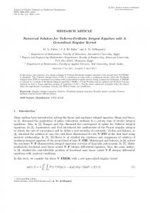
Fig. 1. Schematic view of the two electrode blade-plate configuration.
configurations [7]. The authors retained the Kaptzov assumpof the corona tion stating that, above the threshold voltage discharge, the electrical field at the injecting electrode remains unchanged and equal to its value at the corona inception voltage. This assumption is valid only for wires as injecting electrodes (in this case, the electrical field at the injector is given by Peek law). For a blade or a needle electrode, the curvature is not constant and an injection law must be used. We consider here the 2-D problem of a blade facing a plate as sketched in Fig. 1, with the blade radius of curvature being small compared with the distance between blade and plate. The two coupled equations, Poisson (1) and charge conservation (2), governing the electrical potential and the charge density of the injected ionic species in the drift zone, are in nondimensional form [2], [3] (1) (2) The expression of the dimensional current density (A/m ) is , where denotes the medium permittivity (F/m), the ions diffusion constant (m /s),
0018-9464/$25.00 © 2007 IEEE
1194
IEEE TRANSACTIONS ON MAGNETICS, VOL. 43, NO. 4, APRIL 2007
Fig. 3. Characteristic line and MOC application.
Fig. 2. Initial (harmonic) structured mesh.
the electrical field (V/m), the medium conductivity the mobility of charge carriers (m /V.s) and the (S/m), velocity field of the medium (m/s). In gases, the medium conductivity is zero and the diffusion and convection currents are negligible compared with the drift current. After some simple derivation, we deduce the following nondimensional form for (2) [2], [3]: (3) The (nondimensional) boundary conditions associated with (1) are of Dirichlet type on the electrodes: , . The Neumann condition applies on the axis of symmetry and on the field line of the harmonic field which bounds the domain at a distance high enough from the blade edge (Fig. 2). Only one boundary condition concerning is associated with (2): the charge density must be prescribed at the injector [1], [3]; the simplest injection law accounting for the observed phenomena in gases is (4) with taking high values. This relation holds at every point of the injecting electrode where the field is greater than for corona inception (when the threshold field , we take ). For the blade-plate geometry, (1) and (3) are solved numerically.
redefinition of the structured mesh is the most difficult step in this paper [2], [3]. We determine the potential distribution between the two electrodes by solving Poisson equation with the finite element method (FEM) applied on the triangular structured mesh of the first order; the triangles are obtained by dividing every quadrangle in Fig. 2 with the diagonal [2], [3]. Using the finite volume method (FVM) to solve (3) and obtain the charge density between the two electrodes, introduces the difficulty of a local minimum appearing in the current density at the axis of symmetry [2]. The charge (3) is solved here by using the method of characteristics (MOC) which is a good method for hyperbolic equations. By developing (3), we have
In this method, we follow the charge from an initial point on the blade up to the plate. In a quadrangle, the space charge leaves and goes to the point (Fig. 3); this movement the point of space charge is affected by the influence of electrical field . would be given by For a fixed mesh, the value of at
The charge density at point would be determined by some kind of interpolation between the charge density values known and . This way of determining , results in an at points important numerical diffusion. With our redefined mesh, the is determethod of characteristics MOC simplifies and only because the nodes and are lying on mined from the same field line (this technique was already used in the case of a blade of hyperbolic shape [2], [3]). IV. EXPERIMENTAL STUDY
III. NUMERICAL TECHNIQUE There are no commercial programs for the computer simulation of this problem as of yet and there is no accurate numerical model for solving the two coupled (1) and (3) in the corona discharge in the gas. These two coupled equations will be solved by successive approximations with an under-relaxation procedure. We use a structured mesh which is redefined at each iteration. The nodes of this structured mesh are the intersection points of selected electrical field lines and equipotential lines (Fig. 2). The
The experimental equipment to perform this study is simple (Fig. 1). For negative polarity of the blade, the corona discharge is inhomogeneous and unstable along the blade edge (tuft corona). It is the reason why the study was carried out with corona discharge of positive polarity. All the results presented here were obtained for a thin blade (thickness: 0.3 mm) with 0.15 mm (this blade induced a more radius of curvature stable corona discharge than other blades of higher thickness and radius of curvature).
KHADDOUR et al.: NUMERICAL SOLUTION AND EXPERIMENTAL TEST FOR CORONA DISCHARGE BETWEEN BLADE AND PLATE
1195
Fig. 4. Variations of I=V as a function of the applied voltage V for three values of the distance d (r = 0.015 cm).
Fig. 6. Current received by the probe electrode versus the normalized distance to the symmetry axis for several applied voltages (d = 2.45 cm, r = 0.015 cm).
Fig. 5. Curve I=V = f (V ) for the distance d = 1.2 cm measured during two different days (r = 0.015 cm).
The characteristics I–V and the current density on the plate have been measured for different values of the distance . Fig. 4 shows the variations of as a function of . A nearly perfect straight line is obtained in the limited range of applied voltage. for the investigated distances from the curves We can get : 20.42 kV for 2.45 cm, 18.67 kV for 1.8 cm, and 15.46 kV for 1.2 cm. Note that the mean electrical field ranges from 10 up to 20 kV/cm, which are rather high values in atmospheric air. As it is well known, several physical parameters influence the corona discharge in atmospheric air: temperature, pressure, and and the mobility of ions depend humidity. Fig. 5 shows that on the environment parameters. By comparing the slopes of the two characteristics determined during two different days, we of charge carriers for day 1 is greater see that the mobility than for day 2; moreover, . It is, therefore, necessary to perform all measurements corresponding to a given value of the distance in the shortest possible time. The measurement of the current distribution on the plate was performed by inserting in the plate a small rectangular electrode insulated from it. This small elongated electrode is parallel to the blade and its effective area is 11 mm 0.6 mm within a few percent. A translation table was used to displace the blade parallel to the plate and in the direction normal to the blade. Fig. 6 shows the variations of the measured current captured by the small electrode as a function of the normalized abscissa on the plate. As the width of this electrode is very small compared to , we obtain a very good approximation of the current density profile. The profiles of Fig. 6 exhibit a good symmetry as expected. It
is clear that the width of the injecting zone on the blade edge is very restricted. We see from the curves of Fig. 6 that the width of the space charge zone on the plate increases with the applied voltage. We also note on the profiles a steep decrease of the current down to zero at a certain distance (the smoothing is partly due to the finite width of the measuring probe). This steep decrease is the image of the quasi-discontinuity of the charge injection intensity on the blade. V. RESULTS AND DISCUSSION In order to obtain numerical solutions, we used the technique of mesh redefinition described in [3]. Several parameters involved in the mesh redefinition had to be adequately modified or adjusted to take into account the effect of the blade thinness. The algorithm using the FEM, the MOC, and the redefinition of the structured mesh converges after about 90 iterations for 35 nodes, despite the use of the injection law (4) which tends to induce oscillations. computation was stopped when the mean relative error on charge density was of the order or smaller). The results appear satisfactory as the total of current flowing from blade to plate is conserved to within a very few percent. The profiles of current density on the collector calculated for several values of the applied voltage (Fig. 9) exhibit a quasi-discontinuity like the measured current density distributions. It is clear that the width of the space charge zone is determined by the injecting zone on the blade which, itself, dethrough the injection pends on the local difference law (4). We note in Fig. 7 the difference between the charged (continuous lines) and the charged zone zone for (dashed lines). The parameter in (4) has a for limited influence on the charge density on the blade and a very small effect on the current-voltage characteristic as can be seen in Fig. 8. In Fig. 8, the excellent agreement between the measured and computed current-voltage characteristics has been obtained by retaining for the mobility of positive charge carriers the value
1196
IEEE TRANSACTIONS ON MAGNETICS, VOL. 43, NO. 4, APRIL 2007
Fig. 7. Field lines in the charged zone for V =V = 1:1 (continuous lines) and for V =V = 2 (dashed lines). The injection law (4) is used with A = 100 (r=d = 0:01).
Fig. 9. Computed and experimental normalized current density, r = 0.015 cm, d = 1.8 cm.
VI. CONCLUSION
Fig. 8. Numerical and experimental nondimensional values of V =V (r = 0.015 cm, d = 1.8 cm).
I =V
versus
2.03 10 m V.s fully consistent with the usual published ones. This agreement gives a first test for the validity of the injection law used in the numerical modeling. A second test, much more sensitive, is provided by the comparison of the computed and measured profiles of current density on the plate. Fig. 9 shows that the measured values made nondimensional by using, in particular, the previous determination of , agree fairly well with the calculated ones (the indeterminacy mainly arises from the area of the small electrode). The shapes are similar and exhibit a steep decrease at the boundary of the charged zone. The width of space charge zone appears to be fairly well predicted by numerical calculations. Such a good agreement was obtained for moderate values of the 20 kV and 22 kV (not much higher applied voltage 18.7 kV). The difference between the two curves for than 24 kV might partly arise from the shape of the blade edge which probably slightly differs from the perfect hemi-cylinder retained in the numerical model. Very likely the main reason for this difference is the appearance, at higher applied voltages, of intermittent streamers of limited extent resulting in higher mean current densities and more acute profiles (see also Fig. 6).
The numerical code using the techniques MOC and FEM with redefinition of the structured mesh and the retained injection law, gives solutions which satisfactorily predict the variations of the total current and the profiles of current density on the plate in the configuration of a thin blade facing a plate. There should be no particular difficulty to use this algorithm to solve the problem in the axi-symmetrical point-plate configuration (the case of “barbed” electrodes—points placed on a wire and facing the plate—could be also treated by replacing such electrodes by an equivalent blade). However, the adaptation of the algorithm to real 3-D configuration is not straightforward and requires further work. REFERENCES [1] K. Adamiak and P. Atten, “Simulation of discharge corona in pointplane configuration,” J. Electrostatics, vol. 61, pp. 85–98, 2004. [2] P. Atten, J.-L. Coulomb, and B. Khaddour, “Modeling of electrical field modified by injected space charge,” IEEE Trans. Magn., vol. 41, no. 5, pp. 1436–1439, May 2005. [3] B. Khaddour, P. Atten, and J.-L. Coulomb, “Electrical field modified by injected space charge in blade-plate configuration,” IEEE Trans. Magn., vol. 42, no. 4, pp. 651–665, Apr. 2006. [4] J. Butler, Z. J. Cendes, and J. F. Hoburg, “Interfacing the finite-element method with the method of characteristics in self-consistent electrostatic field models,” IEEE Trans. Ind. Appl., vol. 25, no. 3, pp. 533–538, May/Jun. 1989. [5] P. L. Levin and J. F. Hoburg, “Donor cell-finite element descriptions of wire-duct precipitator fields, charges, and efficiencies,” IEEE Trans. Ind. Appl., vol. 26, no. 4, pp. 662–670, Jul./Aug. 1990. [6] M. Abdel-Salam and Z. Al-Hamouz, “Finite-element analysis of monopolar ionized fields including ion diffusion,” J. Phys. D: Appl. Phys., vol. 26, pp. 2202–2211, 1993. [7] A. M. Meroth, T. Gerber, C. D. Munz, P. L. Levin, and A. J. Schwab, “Numerical solution of non stationary charge coupled problems,” J. Electrostatics, vol. 45, pp. 177–198, 1999.
Manuscript received April 24, 2006 (e-mail:
[email protected]. inpg.fr).