from the study of engine inlet wave propagation. ..... in duct wave propagation. This is part of our ongoing work. Complete details ..... Supplementary Notes.
NASA Contractor Report 172434 ICASE REPORT NO. 84-39
NASA-CR-172434
19840025041
ICASE
_. _.2_(L
....
....
: :- _'-'_" "_
s' -j
NUMERICAL SOLUITONS PROPAGATION PROBLEMS COMPUTATIONS
S.
WAVE
I. Hariharan
Contract August
INSTITUTE NASA
OF ACOUSTIC USING EULER
No. 1984
FOR COMPUTER
Langley
Operated
NASI-17070
Research
APPLICATIONS Center,
by the Universities
IN SCIENCE
Hampton,
Virginia
Space Research
AND ENGINEERING 23665
Association
National Aeronautics and Space Administration
LANGLEYRESEARC_ ,3kr'_TER LIBRARY,r_IASA
Langley Research Center Hampton.Virginia 23665
HA,_,_PTON, VIRGINIA
NUMERICAL
SOLUTIONS
PROBLEMS
OF ACOUSTIC
USING EULER
WAVE PROPAGATION
COMPUTATIONS
S. I. Hariharan* University of Tennessee Space Institute Tullahoma, Tennessee 37388 and Institute for Computer Applications in Science and Engineering NASA Langley Research Center, Hampton, VA 23665
Abstract This paper reports solution procedures for problems arising from the study of engine inlet wave propagation. The first problem is the study of sound waves radiated from cylindrical inlets. The second one is a quasi-one-dimensional problem to study the effect of nonlinearities and the third one is the study of nonlinearities in two dimensions. In all three problems Euler computations are done with a fourth-order explicit scheme. For the first problem results are shown in agreement with experimental data and for the second problem comparisons are made with an existing asymptotic theory. The third problem is part of an ongoing work and preliminary results are presented for this case.
Research was supported by the National Aeronautics and Space Administration under NASA Contract No. NASI-17070 while the author was in residence at ICASE, NASA Langley Research Center, Hampton, VA 23665.
i
[
I.
Introduction A considerable amount of work has been done in the past to
understand acoustic wave propagation problems.
They occur
in
several situations such as sound radiation from engine inlets, exhausts
and
underwater
acoustics.
In
this
paper
we
are
primarily interested in the problems arising from engine inlets, but
the
methods
we
develop
here
underwater acoustics problems too. two parts.
nonlinearities.
applicability
to
These type of problems have
Both have complex wave structures due to
One likes to calculate the sound pressure field
inside the
accomplished
the
The first one is the inlet wave propagation and the
other is the radiation.
both
have
by
inlet
and
solving
in the
both
atmosphere.
parts
together,
This can which
be
becomes
computationally complex, or by a coupling procedure by solving in the inlet and then in the atmosphere separately. A great deal of engineering literature exists on this subject, in particular for linear problems.
This paper is intended to report a sequence of
successes of Euler
computations of both
acoustic wave propagation from inlets. natural
way
of
doing
these
linear and nonlinear
It turns out this is a
calculations,
since
the
field
equations are obtained from Euler equations. The difficulties in this approach are mostly attributable to treatment of boundary conditions. arise
when
numerically.
one
wants
to
Particularly, the difficulties
prescribe
boundary
conditions
It is known in linear wave propagation problems
that it is difficult to prescribe farfield boundary conditions
-2-
numerically.
The
Sommerfeld's in the
radiation
far
outgoing
corresponding
field.
waves
conditions.
holds
frequency
the
simulated
by
several
solve a
equation
acoustic
similar
which
in the in
a
near
the
in reference follows
the
envelope
method.
I
the
reference
2
appropriate.
family
the
for
of
is
the
radiation
problem
discussed
linear the
but
we
A
wave
radiation
from
III.
This
solved
the
problems
are
inlet
solutions
subject
sound
does
the not
reflect
is to examine
subject
to area
sound
parameters
be
at
if one
variation
source can
and
the can of
strength. used
to
open
end
attenuate the
inlet, A
reduce
we
to
of
mean
flow
combination noise
from
we
the
and
that
in
goal
section
number
these
engines
the
The
exit
Mach of
which
considered
fact
the
the
in
inlet
inlet.
at
of
from
inlets
the
the
sound
work
implemented
the
concerned,
in
is called
considered
inside
nonlinear
as
is
of
idea
method
work
and
boundary
the
cylindrical
As
combine
version
and
domain
this
simultaneously.
far
to
be
farfield
pattern
problem
can
is another
time
problem
frequency
exact
first-order of
in
nonlocal
There
conditions
sound
of
atmosphere
of
here
of
in Section
context,
models
the
seems
In
as
is
An
the
higher-order
in the
field. 7
9.
of
of
method
context
reflections
conditions
is obtained
scheme
wave
well
such
numerical
the
as
are
behavior
family
farfield
One
which
no
asymptotic
domain
domain
solutions
equations
the
time
methods.
is available
the
2
conditions
guarantees
extract
in
procedure
conditions
to
This In
which
reference
used
domain.
integral
conditions
In was
asymptotic
and
and three these
-3-
facts In
were
demonstrated
this
case
problem.
We
section
of
author no
we
is not
class
of
the
linearized
variable
nonlinear
condition.
be
Such
and
obtain
on
the
are
consider
model
in
Section
V
dictate
of
will
the
procedure V
are
the
and
end
due
an
In
incoming
approximate
to
specifying
IV
a
strictly
to
outgoing
the
obtain
for
inlet.
incoming
Section
a
exit
that
equivalent in
the and
IV and
open
to
becomes
at
nonlinear
The
open
zero
conditions
waves
end.
can
We and
open
the
condition.
dimensional
acoustic
near
to
a procedure
boundary
in Sections
one
set
of
experimentally.
condition
the
equation
simply
decades
equations
discussed
variables
will
impedance
any
equations
characteristic
of
field
at
two
nature
The
model
problems of
last
different
of
our
the
reflection
inlet.
for
linearization these
a no
aware
reflection
this
face
desire
the
in
an
quasi-one-
two-dimensional
model. In
all
three
fourth-order section. that
we
accurate This
scheme
tried.
In
(Section
IV),
we
became
tried
the
Chebyshev
inlet the
and
essential
order
situation method
a
the
the
is superior
Chebyshev
This
for
this
the
other
next
methods
near
the
end
at
the
we
class
the
fact
points
inaccurate
center but
model
that
to
were
it
believe
a
that
due
calculations
Hence,
in
used
polynomials
was
an alternative,
implement.
than
we
quasi-one-dimensional
with
are
here
discussed
results
concentrated
nonlinearities
to
for
expensive.
is
is
better
method
are
discussed
which
provided
result
technique
problems
scheme
spectral very
a
of
particular
points
as
Multidomain our
classes
of
the
of
because inlet.
is cumbersome that
of problems.
the
the
in
fourth-
-4-
The plan of the paper is as follows.
In Section II we give a
description of the fourth-order method and its usage in higher dimensions.
Sections III, IV, and V contain the description of
each problem under consideration.
Finally,
in Section VI we
present some numerical calculations. We omit derivations of the field equations that we solve in our discussions and we refer readers to references 4 and 5.
The
derivation of field equations of the problem V will be reported in a forthcoming paper.
II.
Numerical Scheme As stated in the introduction the scheme used here is an
extended
version
reference 3.
of
MacCormack's method
and
is developed
in
To provide a brief description let us consider a
single equation of the form
ut + fx = h.
Let
xj (i ( j (N)
domain.
(2.1)
be equally spaced nodes in the computational
Define forward and backward flux difference operators by
P_.(f) = 7f. 3 3 - 8fjeI + fj£2" Then the scheme has four steps.
From a time
nat
it has a backward predictor and a forward corrector
(2.2) to
(n+_2)At
-5-
(i) = un ap-(fn) + 8h(n) uj J 3 J
(2.3) j Un+I/2= 1/2 Uj +
In the next
At/2
j
+ aP
f
+ 8h
.
time-step it is changed to a forward predictor
and a backward corrector stage as follows:
u!l) = un+ 1/2 + ap+ fn+ 1/2 + Bhn+ i/_
J
J
J
3
(2.4)
where
a = At/6Ax, 8 = At/2
and
the
superscript
(i) denotes
predicted values. The other subscripts have the usual meaning of values evaluated at the indicated time step.
From (2.2) one must
notice that the fluxes are not defined at the end points, namely at
j = 0,i and at
extrapolations.
j = N+I, N+2.
There one can use suitable
In all problems discussed here we used a third-
order formula as follows:
fj = 4fj+l - 6fj+2 + 4fj+3 - fj+4'
(j =0, -i) (2.5)
fj+l = 4fj - 6fj_1 + 4fj_2 - fj-3'
(J = N, N+I)
-6-
In
more
technique.
than
one
dimension
we
use
operator
Let us consider the following two-dimensional system:
w t + --x F + --y G = -H.
If
splitting
Lx(At/2) and Ly(At/2)
(2.6)
denote symbolic solution operators to
the one-dimensional equations
W t + F x : H1 (2.7)
w t + Gy = H2.,
in which
H I and H 2
are suitable decomposition of
H,
then we
solve (2.6) by n+ 1/2 w
n = L x Ly w
(2.8) wn+l = L L wn+ 1/2 -y x --
It must be noted that the operators form for each
At/2
above splitting
Lx
and
Ly
change their
interval according to (2.3) and (2.4). The
is known to preserve second-order accuracy in
time and does not change the spatial accuracy of the scheme. The stability criteria is chosen in such a way that it is common for both equations in (2.7). The
last
aspect
artificial viscosity
we
consider
here
is
to resolve shock waves
the
addition
of
for the problems
-7-
considered
in
conservation
Section forms
of
IV. the
The
equations
considered
there
are
nature
w t + f(w) x = 0.
The
artificial
is of
the
where
viscous
of
term
added
to
(2.9)
(2.9)
is of
second-order
and
form
_ = 0(i)
and
p
is the density.
The difference form of
this is
" _-_ IPj+1 - pjll_j+l - _j)
I Pj - Pj-II(_j - _j-l)] " This is a second-order formula.
Thus we settle for less accuracy
in the presence of shocks to obtain sharper shocks.
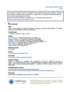
III. Problem of Sound Radiation From Unflanged Cylindrical Inlets The problem studied in reference 4 is presented here.
The
same problem has been studied experimentally15 and analytically using
Wiener-Hopf techniques.13
radiated sound
in the atmosphere
pressure field inside the inlet.
The goal here is to calculate subject to a
given acoustic
Euler computations for this
-8-
problem were done only in the absence of mean flow.
With mean
flow, which simulates flight situations, results are available in reference 7.
Here
we present
the
equations and
approximate
boundary conditions for sound radiation for an incident spin mode 'm'
(m)0)
of sound pressure wave at the left end of the inlet
which is cylindrical (see Figure i).
The field equations in this
case are _p + v + imw_ 8--_ + Uz + Vr r
0
Du 8P = 0 "FE + %-£ (3.i) _v _p _ %-£ + %-f - 0
8w im 8--_ + _---p = 0
where
(u,v,w) are components of acoustic velocity in
coordinates and case
m = 0
p
and
is the acoustic pressure.
(z,r,8)
For the plane wave
w = 0.
The problem here then is to solve the system (2.1) subject to an incident field of the form
i£mZ p " e
together with hard
ikt JmIlm(r/a))e
(3.2)
wall conditions on the inlet (duct) wall and
radiation condition in the atmosphere. zeroes of the Bessell function
J'(z) m
In (3.2) and
a
lm
are the
is the radius of
-9-
the
duct
and
£m
are
related
to
the
£m = /(ka)2
By
considering
at
the
inflow
left
the end
of
reflected the
8v
and
by
(3 3)
"
travelling
(3.1)
ka
in the
(3.2)
give
-z
direction
the
following
wall
of
z (r)t
u t = -2ike
m
Jm
Im
e
(3.4)
Im J'mIlm (r/a) 1
8--t+
the
12 m
number
conditions
P + _m
On
-
waves
inlet
wave
the
a JmIlm(r/a)
] '
p : 0.
(3.5)
inlet 8P 8r - 0
which the mode
is axis
the
standard
takes
number.
rigid
different
They
wall
forms
(3 6)
condition. depending
on
The
conditions
the
incident
on spin
are
v = 0 v + iw = 0 v = O, w = 0
on r = 0 on r = 0 on r = 0
(m = O) (m I) (m) 2).
(3.7)
-i0-
FarFieldBoundary
73
72
Directivity Measurement
" ,, "
_'1
× ! !
i
\
D I nflow Boundary
Semi-Infinite Inlet s
s
i_,,
i | \i
_
i, z
fs
t
Y
Figure 1
In
the
one
atmosphere
needs
distances. of
such
we
this
circle
of
of
apply
for such
domain
at
Then
duct
R
from
and
the
conditions
of
reference
2 at
71,
and
73.
This
72
situation
to
be
several
problems
each
larger
domain
one
origin
(which
each
point
can
condition
and the
can
one
these
in
needs
the
Figure
taken
far
families
construct is
line) of
on
at
presented
than
See
point
center
are
conditions
distances
Thus
imposed
introduction
model
at
the
on
to
reflection.
measurements.
computational
radius
without
boundary
directivity
purpose.
the
in the
conditions To
of
radiates condition
mentioned
desires
boundaries
end
As
2.
one
for
nonreflective
computational
where
sound
a
boundary
reference finite
the
region 1
again
farfield locally
at
apply
the
u +
v
sin
u)
+ p
a
open
radiation
boundaries be
shown
for
this
be
_--_SP - (u cos
a
=
0,
(3.8)
-ii-
where
a
is the angle measured from the z-axis to a point on
YI' Y2 or Y3" With the above formulation and with the scheme given in the last section the solution was achieve
a
supplied
steady
from
started at a state of rest to
time-harmonic
the
state.
inflow conditions.
Time The
increments
solution
are
for this
problem will approach the solution of Helmholtz's equation times eikt.
(It is immediate from (3.1) upon taking Fourier transform
with respect to time that one obtains the Helmholtz equation.) The
philosophy
mathematicians
behind
this
the
limiting
as
procedure
is
amplitude
known
among
principle.
The
advantage of doing this problems in time domain is that one does not
encounter
the
problem
of
resolving
or
calculating
the
interior eigenvalues in the inlet.
IV.
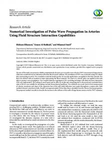
Quasi-One-Dimensional Model In this section we describe a simplified nonlinear situation
which
has
been
phenomena.
popular
in
analyzing
the
nonlinear
wave
We summarize the work appearing in references 5 and
6. This model is depicted in Figure 2.
The duct corresponds to
the inlet situation and it has a constriction at the center. There
is
a
steady
flow
from
right
to
left
propagates from a source upstream of this flow.
and
the
The derivation
of field equations used here are available in reference 5. are
sound
They
-12-
qt + lUsq + qsu + Uq)x = 0
ut + where u
and
UsU +
q = Ap p
quantities
with
+ Cs
(4.1)
--_--qq
A = A(x)
x = 0,
in the area variation of the duct
are acoustic velocity and density respectively. with
components and
subscript cs
s
denote
the steady mean
is the local sound speed in the flow.
The flow The
problem is then to solve (4.1) subject to
u(0,t) = f(t)
(4.2)
B(q,u) (l,t) = 0
(4.3)
Acoustic Source
•.
-I
0
Termination
•
_
••
N.I N+2
I
I
I
I
I
0
0.25
0.5
0.75
1.0
Axial Position,x/L
Figure 2
-13-
where in (4.2), f(t) (4.3)
B
denotes a source which varies in time.
In
is a linear operator which will give no reflections at
the exit (i.e., at x = i). As mentioned in the introduction (4.3) is derived upon linearization of (4.1). This process yields
(q)t = 0
+A
U
(4.4)
X
where
A
(us
=
Cs2/q s
The eigenvalues of this matrix are
u
s
+ c
s
and
u
s
- c
s"
The first one is positive and the other is negative.
These signs
give the characteristic directions of propagation.
We form the
matrix
T
from the eigenvectors so that
T-I A T is diagonal.
Then the characteristic variables are
(vl) =
v2
This gives
T-I
.
(4.5)
-14-
_ Vl
q + u qs cq (4.6)
_
v2 where
vI
u
Cs
corresponds to the positive eigenvalue and
negative one. which
q +
qs
is
set
At the right boundary to
zero
to
obtain
vI
v2
to the
is the inflow variable
the
nonreflective
boundary
condition (4.3), i.e.,
B(q,u) (l,t) -
We
remark
here
discussed
that
for
the
q qs
u _ 0. Cs
fully
two-dimensional
in the next section a similar procedure
problem
is used to
obtain this type of boundary condition. As far as the source term is concerned it is driven with a harmonic input f(t) = A cos t
where
A
is the amplitude of the source.
Once again the numerical procedure described in Section II is applied
to get accurate smooth solutions.
For high Mach
numbers and high source strengths the artificial viscosity which was discussed in that section was added to obtain solutions. As mentioned in the introduction the goal in this class of prob/ems is to study the attenuation of sound pressure level at the exit
section.
It was experimentally observed
that
high
-15-
source
strengths
reasons. and
and
This
is
a discussion Using
(lower boundary
V.
is
ongoing reported
are
recently
in
one
situation We
the
equations
given
mean
and
last
here
of
Let
corresponding
mean
The
Their
scheme
treatment
of
ours.
pressure
The
a
u, v,
field
a
has
also
Then
of
of
our
will
be
combination
procedure
been is
of
studied
similar
configuration
equations
equations flow p
then p
velocity 's'
on
the
is determined
we are
and
and
component
flow.
part
procedure
using
physical
field
subscript
is
solution
last
of
to this
3.
perturbed
y
the
the
effects
This
solution
These
Let
in
two-dimensional
solutions
Our
the
the
described
situations
in Figure with
work
of
section.
velocity,
respectively.
solution
numerical
14.
propagation.
numerical 12.
state.
component
the
seek
wave
situation.
Euler
in
Similar
is depicted begin
possible
numerical
different
from
are
VI.
reference
details
reference
nonlinear
(5.1).
duct
elsewhere.
in
in
to
Complete
in
this
flow
Model
us
theory
in
with
different
motivated
asymptotic
mean
in Section
available
obtained
work.
the
demonstrated
results
nonlinearities
of
equations
Two-Dimensional
section
the
Euler
conditions
The
the
being
number
is available
full
order)
Mach
the
use
to
derived
density
the
from
acoustic and
quantities
from
from
subtracted
denote
field
simulate
equations isentropic
a x
pressure
denote are
the given
relation
-16-
as given in (5.2).
B-_ %-_ Psu + UsP + pu + _
_-_ psu + UsP + pu
+ -_
+ -_
psv + VsP + pv = 0
2 0sU2 )
2PsUsU + Usp +
+ 2UsPu + p
PsVsu + PsUsv + UsVsP + Psuv + UsPV - VsPU
= 0
(5.1)
_-_ psv + VsP + pv
+ @--_PsUsv + PsVsu + UsVsP
+ PsUV + UsPV + VsPU )
+ _-y @ (2psv sv + Vsp 2 + psV2 + 2v spv + p) = 0
P = c2[ Is
where
+ /_
c2 = yps/Ps
(P/Ps)IP
(5.2)
is the local sound speed in the flow.
The
system (5.1) has the form @8
@F
@G
@--_ + _-_+ @--_ = 0.
where
_
=
(81,
82 , 83 ) and
(5.3)
-17-
81 = P 82 = psu + UsP + pu B3 = psv + VsP + pv
u,v and
p
are determined by
U =
82 - us 81 Ps + B1
(5.4) V =
83 - vs 81 Ps + B1
and P =
81 •
YJ
Inflow _ Boundary_
y= d(x)
AcousticWaves
Inlet Wall /
i....--Termination I Boundary
IL._
._L!
MeanFlow _--x
I
II I
Figure 3
Two-Dimensional
-18-
The area variation (see Figure 3) is included as follows.
Let
the contour of the area variation be given by y = d(x).
We introduce new variables
=
X
n= so that n = 1
y
,
(5.5)
will be the surface of the inlet.
This change of
variables allows us to do the computation in a rectangle, but the system (5.3) takes the form
-_
(dS)
+ -_
(dF) + -_
(G - _Fd')
= 0.
(5.6)
This system is solved together with an inflow condition and a nonreflective
condition
at
exit
plane.
On
the axis
the
y
component of the velocity is set to zero and on the wall normal component of the velocity is zero.
To derive the nonreflective
condition at the exit plane we considered the variation of (5.6) only in the
x
direction, i.e.,
(d_8)+ _
(dF) = 0.
(5.7)
-19-
This
equation
variables
as
condition
that
is
then
indicated comes
the
means
the
in
out
•
For
linearized
of
to
Section
this
obtain
IV.
procedure
characteristic
The
nonreflective
is
82 - (cs + us)81 = 0.
source
plane
pressure
wave
incident
is prescribed.
(5.8)
conditions
Upon
are
linearization
used of
which
(5.2)
we
have _ p(O ,y,t) P
C
2 S
or
81 = p(0,y,t) 2 c
(5.9)
s
This completes numerical sample
VI.
the
statement
of
the
problem.
Again
the
scheme described in Section II is applied to get a
solution
reported
in the
next
section.
Discussion of Results For the sound radiation problems discussed in Section III
the computations were performed typical grid sizes were at
eight diameters
origin. distance
on a Cyber-203 machine.
115 × 35.
(diameter of
The
The source boundary was kept the cylinder)
away from
the
The sound pressure levels were calculated on a circle at 10 diameters away
from the open end.
The farfield
-20-
boundary was chosen to enclose this circle. results with
a
result of
Wiener-Hopf technique.
reference 12 which
was
done
using
An experimental study to simulate this
situation is available in reference 15. spinning mode
We compared our
In this experiment a
synthesizer was used to produce both plane and
spinning mode waves.
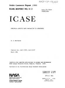
A sample result comparing our results with
both results of references 12 and 15 is presented in Figure 4.
0 -5 -I0( -15 -20 -25 dB, Level -30
0 [] 0
-35 -40 -45 -50 -55 -60 -65 0
I I0
I 20
ExperimentalData(ref 15) SavkarTheory(ref 13) Numerical ka = 3.370 Mode= 2
I I I I I I 30 40 50 60 70 80 Angle,deg
I 90
Figure 4
This comparison was made for a wave number the spinning mode number
m = 2.
ka = 3.37
and for
In this result theoretical, ex-
perimental and numerical results are in good agreement, except
-21-
near
the
fact
that
other
origin
for
in the and
to
reference
For
the
compare
an were
interested
in
were
with
of
the
to Mach
comparisons
the
throat
gas
explicitly.
numbers
Solid the x/L
-.90 lines
are
asymptotic = 1.00
For
refer
for the
this
higher
one
on
a
computations reference
(i -
in
IMtl),
is shown dB
source
results
of
our
results
respectively
at
the
where
L
This
examples
the
steady us
a
is
the
length
.75
of
the
and
throat
a throat
=
the
asymptotic
frequency
x/L
be
typical
levels
The
at
ohecan
the
the
5 for
and
with
pressure
computations.
is the
linearly
-.50
Mt
the
contour
the
Since
where
station
of
was
theory
with
The
particular
compared
I0.
in Figure
140
a
Ps and
are
sound
this
I0.
for
by
are
comparisons
ii.
configuration
The we
accelerates
satisfied
at
reasons
to
number
to
made.
description
flow
Mach
attempt
reference
reference
entry
in
the
In particular
equations
arises
of
applied
mean
an
8) was
A detailed
the
Euler
model
of
was
in
the
A comparison and
IV
throat.
developed
chosen
number.
we
However,
theory
that
approaching
was
is one
duct.
here
The
situation
control
comparisons
model.
available
a way
dynamic
nonlinear
number
is
(Mt).
theory
more
(reference
This
Section
at the
asymptotic
Mach
in
given
-.90
dimensional
good.
asymptotic
duct
one
to the
to completely
nonlinear
result
Crocco-Tsien
number
parameter
For
two-dimensional
in such
and
Mach
so
the
the
is designed
solved
not
called
contour
waves.
is due
4.
discussed
geometry
This
it is difficult
experimental
comparisons
procedure
plane
results.
quasi-one-dimensional
with
made
experimental
experiment
modes
readers
the
Mach
452
Hz.
others
are
and duct.
at
-22-
-8
[]
Asymptotictheory (ref 10), x/L = 0.75
O
Asymptotictheory(ref 10), x/L = 1.00 Finite Difference
-4 u
(l_lMtl_Z o %4
-.8
I
I
7T/2
_T
I
3zr/2
I
27T
Time,t
Figure 5
Shock results are also in good agreement (see reference 6).
As
far
is
as
the
sound
reduction
at
the
termination
section
concerned a result for a higher sound pressure level (156 dB) for the source
is presented
in Figure 6.
In this case acoustic
shocks occur and cause energy loss and we can see at 5 dB sound pressure level drop at the termination section.
Mt = O.90 180 Sound 170 Pressure Level,dB 160
150 0
0.25
0.50 Axial Distance,x/L
Figure 6
0.75
I 1.00
-23-
Around this source pressure level (156 dB) Figures 7 and 8 for absolute value of throat Mach numbers increasing from .70 to 90 we have shown that the pressure level reduction is increasing and the
wave
forms
starting
from a
smooth stage
becomes steeper showing the shock phenomena.
and
ultimately
Figure 7 shows
acoustic suppression and Figure 8 shows the distortion of wave form.
This
validates
the
experimental
suggestion
that
the
increase in the Mach number attenuates sound at the termination or the exit section.
180 -
170 -
MachNo.(Throat) .70 .80 .90 .85
//_
SPL 160
I50
140 0
I 0.2.5
I I 0.50 0.75 Axial Position, xlL
I 1.00
Figure 7
[
-24-
3.0 -
MachNo.(Throat) 30 .80 .85 .90
1.5 \
AcousticVelocity 0
7 ;t /
-.
\ !
_.k__..l__-
..--;--j;
L,
..
/
-1.5
-3.0
I M2
0
I _" Time,t
--// I 3;T/2
I 27r
Figure 8
For the two-dimensional model we discussed in Section V we needed
a
two-dimensional
flow.
To
simulate
a
situation we
considered again the one-dimensional flow solution us and Ps but we introduced the y component of the velocity according to
d'(x) Vs(X,y) = _
y •
This is valid (see reference 12) provided the variation of is small.
(6.1)
d(x)
For the two-dimensional case the shocks were predicted
at low Mach numbers (reference 12).
Here we present a sample
result that for a throat Mach number -0.85 and a 135 dB source. Here we observed a i0 dB sound pressure with reduction on the
-25-
axis
at
the
reduction
was
termination observed
Langley
(reference
will
reported
be
8). in our
section.
in an As
The
experimental we
mentioned
forthcoming
paper.
same study
before
pressure conducted the
full
level at NASA results
-26-
References
[i] Astley, R. J. and W. Eversman, "Wave Envelope in Infinite Element Schemes for Noise Radiation from Turbofan Inlet," AIAA-83-0709 (1983).
[2]
Bayliss, A. and E. Turkel, "Radiation Boundary Condition for Wave-Like Equations," Comm. Pure AppI. Math., 33, No. 6 (1980), pp. 707-725.
[3] Gottlieb, D. and E. Turkel, "Dissipative Two-Four Methods for Time-Dependent Problems," Math. Comp., 30 (1976), pp. 703-723.
[4] Hariharan, S. I. and A. Bayliss, "Radiation of Sound from Unflanged Cylindrical Ducts," ICASE Report No. 83-32, NASA CR-17217 (1983), to appear in SIAM J. Sci. Statis. Comput., 1984.
[5]
Hariharan, S. I. and H. C. Lester, "A Finite Difference Solution for the Propagation of Sound in Near Sonic Flows," J. Acoust. Soc. Am., 75 (4) (1984).
[6] Hariharan, S. I. and H. C. Lester, "Acoustic Shocks in a Variable
Area
Duct
Containing
Near
Report No. 83-64, NASA CR-172274 Comput. Phys., 1984.
Sonic Flows,"
ICASE
(1983), to appear in J.
-27-
[7]
Horowitz, Finite
S. J., Element
Radiation 0124
[8]
Jones,
M.
G.,
R.
C.
Inlets
in
Zinn,
for
"An
Iterative
Predicting
Steady
3
(1980),
Flight,"
Sound AIAA-82-
K.,
a Nearly
Myers,
M.
K. of
Sound
Myers,
M.
K. of
S. D.
Acoustic
(1975).
Sound
Inlet,"
M.S.
(1982).
"A
Problems,"
Finite
Element
Internat.
Flow,"
A.
J.
J.
and
51
K.
in
Method
Math.
Sound
AIAA-81-2012
Calleghari,
Acoustic
Vib.,
and
Marin,
Choked
Math.
(4),
Transmitted
(1981).
"On
the
Theory
in
Near
(1977),
pp.
517-531.
Uenishi,
Through
a Near
Singular
Sonic
"Two-Dimensional
Transmission
AIAA-84-0497
Savkar,
P.
Development
Sound
Number
University
"Shock
Linear
J.
Mach
of
311-350.
and
Flows,"
Investigation
Subsonic
S.
pp.
Through
Flow",
High
Interface
M.
Analysis
Experimental
and
Myers,
Duct
B. T.
Technique
Washington
Exterior
Behaviour
[13]
a
George
Sci.,
[12]
"An
in
MacCamy, for
[ii]
Turbofan
and
(1982).
Thesis,
[i0]
Sigman
Integral
from
Attenuation
[9]
R. K.
Duct
Nonlinear Sonic
Throat
(1984).
I. H.
Modes
Edelfelt,
with
Flow
"Radiation Mismatch,"
of Cylindrical NASA
CR-132613
-28-
[14]
[15]
Walkington
N.
J.
and
Solutions
to Shocked
Ville,
M.
of
J.
the
Bellmouth
and
Radiation Including
W.
Eversman,
"Finite
Waves,"
AIAA-83-0671,
Acoustic
R. J. of
Silcox,
Sound
the
Flow
from
"Experimental an
Effect,"
(1983).
Investigation
Unflanged NASA
Difference
Duct
TP-1697,
and 1980.
a
I.ReportNo. NASA
CR-172434
ICASE Report
2. Government AccessionNo.
3. Recipient's Cat_logNo.
No. 84-39
4. Title and Subtitle
5, Report Date
Numerical Solutions of Acoustic Wave Problems Using Euler Computations
Propagation
August 1984 6. Performing Organization Code
7. Authoris)
8. Performing Organlzation
S. I. Hariharan
Report No.
84-39 10. Work Unit No.
NameandAddress for Computer Applications
9. Performing Organization
Institute
in Science
and Engineering
11. Contract or Grant No.
Mail Stop 132C, NASA Langley Hampton, VA 23665
Research
Center
NASI-17070 13. Type of Reportand PeriodCovered Contractor Report
12. Sponsoring Agency Name and Address
14. Sponsoring AgencyCode 505-31-83-01
National Aeronautics and Space Administration Washington, D.C. 20546 15. Supplementary Notes
Langley Technical Final Report
Monitor:
R. H. Tolson
16. Abstract
This paper reports solution procedures for problems arising from the study of engine inlet wave propagation. The first problem is the study of sound waves radiated from cylindrical inlets. The second one is a quasi-one-dimensional problem to study the effect of nonlinearities and the third one is the study of nonlinearities in two dimensions. In all three problems Euler computations are done with a fourth-order explicit scheme. For the first problem results are shown in agreement with experimental data and for the second problem comparisons are made with an existing asymptotic theory. The third problem is part of an ongoing work and preliminary results are presented for this case.
r
J17. Key Words (Sugg_ted by Authoris}}
18. Distribution
acoustics, inlets, finite differences, Euler computations, shock waves
64 71
Statement
Numerical Acoustics
Unclassified
19. Security_a_if. (ofthisreport) Unclassified
20. Security Cla_if.(of this_ge) Unclassified
Analysis
- Unlimited
21. No. of Pages 30
22. Dice A03
ForsalebytheNational Technical Information Service, Springfield, Virginia2216t
NASA-Langley, 1984