Object Following Control of Six-legged Robot Using Kinect Camera Amruta Vinod Gulalkari, Giang Hoang, Pandu Sandi Pratama, Hak Kyeong Kim, Sang Bong Kim* Department of Mechanical and Automotive Engineering Pukyong National University Busan, South Korea
[email protected] *Corresponding author:
[email protected]
Abstract-This paper proposes a vision-based object following system for the six-legged robot using Kinect camera. To do this task, the followings are done. First, for image processing, a Kinect camera is installed on the six-legged robot.
The interesting
moving object is detected by a color-based object detection method. The local coordinates of the detected object are obtained to provide the position of the object. Second, the backstepping method using Lyapunov function is adopted to design a controller for the six-legged robot to achieve object following. Finally, the simulation and experimental results are presented to show the effectiveness of the proposed control method.
Keywords-six-legged robot; Kinect camera; object following; backstepping control; Lyapunov function
1.
Bong Huan Jun Technology Center for Offshore Plant Industry Korea Research Institute of Ships and Ocean Engineering Daejon, Korea
[email protected]
their location. Using backstepping control method by choosing appropriate Lyapunov function, the system stability is guaranteed for the six-legged robot. Our system is presented in the following sequence. Firstly, the host computer receives the color and depth images from the Kinect camera. A color based object detection method is used for getting the position of an object. Depth map gives the distance between six-legged robot and detected object. Secondly, a backstepping controller using Lyapunov function is designed for the six-legged robot to track the detected object. At last, simulation and experimental results are presented to show the effectiveness of the proposed control method in the object following system.
INTRODUCTION
In robotic vision applications, object detection and tracking is one of the interesting fields of research. There are several researches related to object detection and tracking [1-3]. Most of these research works were implemented either on wheeled or legged mobile robots. As in [4], people following system was designed using wheeled robot. But there are certain limitations with the wheeled configuration as wheels are inefficient on irregular or rough platforms. In [5], a bipedal robot was used. Maintaining stability with such configuration is also difficult. The selection of camera is also an important issue. In [6], a stereo vision system was implemented on mobile robot designed for rough terrain. However, stereo vision technique is expensive as it uses two cameras for 3D perception. Moreover, while designing such kind of system, it is necessary to design the controller for the robot. In [ 7], object tracking using hexapod robot was achieved which proposed a controller based on Lyapunov stability. In this system, to find an appropriate control law was not an easy task. Therefore, a new controller is needed. In this paper, we present an object following six-legged robot using Kinect camera based on backstepping controller method. Six-legged robots are superior to wheeled, bipedal or quadruped robots as they provide better static stability on uneven terrain. With the invention of low cost RGB-D Kinect camera, it has attracted many researchers in the field of robotic vision. Using Kinect sensor, a robot can obtain descent quality images of the environment to recognize objects and detennine
978-1-4799-3080-7114/$31.00 ©2014 IEEE
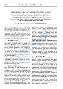
II. SYSTEM CONFIGURATION Fig. 1 shows the vision-based object following six-legged robot using Kinect camera. This system is mainly comprised of a six-legged robot, a Kinect camera, a host computer and a red colored rectangular board as an object for detection and tracking. The Kinect camera sensor is mounted on the top of the robot. Both the six-legged robot and the Kinect camera sensor are interfaced using the host computer.
Kinect Camera
Six·legged Robot
Fig. 1. Vision-based object following six-legged robot using Kinect Camera
In the system, Kinect camera sensor captures image frames with the maximum speed of 30 frames per second and processes them using image processing algorithm to detect an object. Once an object is detected, control commands are sent to control the robot for tracking red colored object.
758
For programming to control both the six-legged robot and the Kinect camera, Visual studio C# Express software is used. Detailed description about six-legged robot and Kinect camera is explained in the following section. A.
Six- Legged Robot
This section describes the configuration of a six-legged robot (6LR ) system used for this experiment. Fig. 2 shows 6LR with its body frame and six legs. Each leg has four rotational joints which can make the robot to get more complex postures and better stability. There are 24 servo motors (each of type Dynamixel AX-12) used to control locomotion of robot by operating 6 legs (24 rotational joints ). On the top of the robot, the mySen-M sensor is attached to measure its angles.
L1. L2. L3 - Left Legs
R1. R2. R3 - Right Legs
Servo Motor
*,--:-:�--l- Robot Body
Fig. 3. Control structure of six-legged robot
Frame
2) Rotational K inematic modeling: Fig. 4(b ) shows the 6LR with its global coordinate frame Xc C Y c ' The rotational kinematic equation for this system is given by,
mySen-M Sensor
"....---,-;- Bluetooth
(20 )
IV. SIMULATION AND EXPERIMENTAL RESULTS To verify the effectiveness of the designed controller, simulations and experiments are done. For the simulation, initial values are chosen as shown in Table I. TABLE I. PARAMETERS AND INITIAL VALUES FOR SIMULATION
::;0
(11 )
Therefore, an angular velocity controller for reducing heading angle error is designed as, (12)
762
= K2ey
Parameters ey
Values 2
Unit m
eo
45 0 0 0. 5 0.0015
deg deg/s mls s
OlO Va
Kl K,
S·l
20J4InternationalConference on Advances in Computing,Communications andInformatics (ICACCI)
The simulation and experimental results are compared and corresponding graphs are shown in Figs. 12-IS. Fig. 12 and Fig. 13 show control input velocities : angular velocity and translational velocity. In simulation result, angular velocity converges to zero after 3 seconds, whereas the experiment result is bounded within ±S deg /s along the simulation result. Fig. 14 shows that the maximum translational velocity for 6LR is 0. 1 mlsec. From simulation result, it is observed that the translational velocity is constant with 0. 1 mls until 7 seconds and then converges to zero. Experimental result shows that the translational velocity is constant with 0. 1 mls until 9 seconds and then converges to zero. 80 .----.---,----,---,---,----,- --"�_�s� ,--i m� u� lat� io �n 9
50�45
------\
---�==��
'\
,, ��
a ... ......... ......... .... ....�- -�":'.-:: - ':'.-!:-:=......... -- -- -
·5
-
-------
I......
-----------------------
-
------
-
..... _ .. _ ....
--- --
-
...
.. \I
,
-----
-
-
..
-
'_'
\
--
.1 % ��0�.5�--7---�1� . 5--�2��� 2 .5 �--3 �--� 3.�5 --�4--� 4� .5��
Time(s)
Fig. 14. Heading angle error 1.2
-- experiment
i--,-----,--,--;:::=::cc:::=.=:=:==;l
1.0 0.8
.........
1]
�
is
0.4
%
Time(s)
-,-
-
---,
-
--,
-,-
,--
-
-
--
-r----;======;J
--
I-si mulation 1 -- experiment
0.15
�
z: 0.1 f-------------. -----l-.,
i
:
� O�
I�
I I
:
I
:
I ...................•....••............
o
\-\.,\
'
...
.0 . 2 1
o
.....
...
..
... ......
. ......
I
2
---
..
4 I
,
�-
....
...
6 I
..
_
..
.. ..
....
-
..
_ ' ....
', .�:� ......--. . ....=::-: :-�.:.�: .,." -! -
....... -..
...
....
I
8
Time(s)
...
.
I
10
I
12
,
14
1
6 1
Fig. 15. Distance error
Fig. 12. Angular velocity 0. 2,
-'.... ""\"
0.2 o
1.� 5 --� 2 --� 2�. 5---+ 3--� 3� . 5--�4--� .4� 5--� .2 ��0�. 5�--�--�
,
6
'..'" �
'...t,
"\"'-'",," 1.................................
:••.......
8
Time(s)
10
12
14
16
Fig. 13. Translational velocity
Fig. 14 shows the heading angle error when the robot turns towards detected object. In case of simulation after 3 seconds, the error converges to zero. The experiment result shows the heading error is bounded within ±SO along the simulation result. Fig. IS shows a result for distance error when the robot is following an object. It can be observed that the distance error converges to zero after 12 seconds in both simulation and experimental results. In the simulation, only kinematic problem of the robot is considered. However, in the experiment the effect of force of the ground and torque of the robot joints cannot be neglected. Therefore, the simulation and experimental results have some difference between them.
The experiment is performed to verify the performance of the proposed system and its results are shown in Fig. 12. For the sake of simplicity, the sequence of events occurred during object following of 6LR with Kinect camera is explained as follows:
1) Fig. 16(a ) shows an initial position of 6LR with Kinect camera. The object is placed on the left corner as shown. In this case, an object is placed at a distance more than 1. 2 meter. The corresponding ROB image shows a position of detected object outside a desired area in the image. 2) Fig. 16(b ) shows a rotating step of 6LR with Kinect camera. In this case, the 6LR is changing its heading angle towards detected object. The corresponding ROB image shows that a detected object image is now inside a desired area after the robot turns towards an object. 3) Fig. 16(c) shows forward moving step of 6LR with Kinect camera. In this event, the 6LR moves towards an object. The corresponding ROB image shows that an object image is inside a desired area. It can be observed that when the robot is closer to the object, a detected object image is closer with the center of desired area and is bigger. 4) Fig. 16(d ) shows the stop position of 6LR with Kinect camera. In this case, the distance between 6LR and object is equal to the reference distance (1. 1 meter ), hence it stops. It is observed that the detected object is exactly in the center of desired area.
2014InternationalConference on Advances in Computing,Communications andInformatics (ICACCI)
763
by the Kinect camera using a color-based object detection method. Based on the kinematic modeling, a controller for six legged robot was designed using backstepping technique and Lyapunov function. The simulation and experimental results verified the effectiveness of the proposed control method for Kinect-based object following six-legged robot with an acceptable error. In the future, dynamic modeling of the six legged robot should be considered and the controller can be developed for better results. ACKNOWLEDGMENT
This study is a part of the results of the R&D project, Development of multi-legged underwater walking-flying robot supported by Korea Government. Authors are indebted to appreciate Ministry of Oceans and Fisheries for the full support to this work.
REFERENCES
Detected object image
(a) initial position
[1]
Z. Jia, A. Balasuriya, S. Challa, "Vision based data fusion for autonomous vehicles target tracking using interacting mUltiple dynamics models," in Networking, Sensing and Control, March 2005, pp. 1081-1086.
[2]
O. Birbach, U. Frese, "A multiple hypothesis approach for a ball tracking system," in Proc. of International Conference on Computer Vision Systems, 2009, pp.435-444.
[3]
N. P. Papaniko10poulos, P. K. Khosla, "Visual tracking of a moving target by a camera mounted on a robot: a combination of control and vision," in IEEE Transactions on Robotics and Automation, Vol. 9(1), February 1993, pp. 14-34.
[4]
G. Xing, S. Tian, H. Sun, W.Liu, H. Liu, "People-following system design for mobile robots using Kinect sensor," in Proc. of 2013 25th Chinese Control and Decision Conference (CCDC), 2013, pp. 31903194.
[5]
H. B. Suay, S. Chemova, "Humanoid robot control using depth camera," in Proc. of 2011 6th ACM/IEEE International Conference on Human-Robot Interaction(HRI), 2011.
[6]
A. Chillian, H. Hirschmuller, "Stereo camera based navigation of mobile robots on rough terrain," in Proc. of the 2009 IEEE/RSJ International Conference on Intelligent Robots and Systems, 2009, pp. 4571-4576.
[7]
M. Mi1ushev, P. Petrov, O. Boumbarov, "Active target tracking from a six-legged robot," in Proc. of 2008 4th International Conference on Intelligent Systems, 2008, pp. 4-56 to 4-61.
[8]
R. A. E1-laithy, J. Huang, M. Yeh, "Study on the use of Microsoft Kinect for robotics applications," in Proc. of Position Location and Navigation Symposium (PLANS), 2012, pp. 1280-1288.
[9]
J. Han, L. Shao, D. Xu, lShatton, "Enhanced computer vision with Microsoft Kinect sensor: a review," in IEEE Transactions on Cybernetics, Vol. 43(5), October 2013, pp. 1318-1334.
(b) rotating step
[10] K. Kungcharoen, P. Palangsantikul, W. Premchaiswadi, "Development of object detection software for a mobile robot using an AForge.NET framework," in Proc.of 2011 Ninth Intemational Conference on ICT and Knowledge Engineering, 2012, pp. 201-206. (c) forward moving step
(d) stop position
Fig. 16. Images showing sequence of events occurred during object following of 6LR with Kinect camera
V. CONCLUSION This paper proposed an object following control system of six-legged robot using Kinect camera. Following steps were executed to achieve object following. Image processing was done using Kinect camera. Object was detected successfully
764
[11] C. D. Herrera, J. Kanna1a, J. Heikkila, "Accurate and practical calibration of depth and color camera pair," in Proc. of 14th Intemational Conference on Computer Analysis of Images and Patterns, 2011, pp. 437-445. [12] G. Hoang, H. K. Kim, S. B. Kim, "Path tracking controller of quadruped robot for obstacle avoidance using potential function method," in International Journal of Science and Engineering, Vol. 4(1), January 2013, pp. 1-5. [13] W. Y. Jeong, H. K. Kim, B. H. Jun, S. B. Kim, "Path tracking controller design of hexapod robot for omni-directional gaits," in Proc. of 2013 9th Asian Control Conference (ASCC), 2013, pp. 1-6.
2014InternationalConference on Advances in Computing,Communications andInformatics (ICACCI)