Object Life-Cycles in Active Relational Databases Fábio A. Machado Porto1, Maurício J. Vianna e Silva2, Sérgio Carvalho3 Departamento de Informática Pontificia Universidade Católica do Rio de Janeiro Rua Marquês de São Vicente 225 Rio de Janeiro, RJ, 22453-900, Brazil {porto1, sergio3}@inf.puc-rio.br
[email protected]
Abstract
One of the biggest problems that object-oriented developers face today is having to integrate at the enterprise level, object-oriented applications with widely applied and quality active relational databases. This paper focuses on the issues of mapping object dynamic behavior into active relational databases. We present a technique for expanding active relational databases with object-oriented behavior semantics, extracted from state transition diagrams expressing object life-cycles. We consider states as first class objects, and discuss state class and event inheritance.
1. Introduction Software development with object orientation is becoming increasingly popular, even in application domains where traditionally procedural programming is the choice paradigm, as for example in real-time and administrative systems. To an extent this increase in use can be traced to the reuse potential offered by the encapsulation of structure and behavior in classes, the building blocks of object-oriented systems, and to the promise of new object-oriented CASE tools, which automate part of the software development cycle. To foster the use of object orientation at the enterprise level, however, where conventional and successful applications are based on widely applied and quality developed relational data bases, much work still needs to be done. The integration of the object orientation and relational paradigms is not easy [ Keller96], and objectoriented applications must find a way to represent the persistence of some of its objects in active relational databases. A general purpose method to integrate object orientation and active relational databases is of importance. Steps in this direction are being taken, as for example in [Gargouri+94, Keller97, Silva97+], which address the mapping of static object models (class and relationship diagrams) to relations. In this paper we extend this work by considering the mapping of object behavior to active relational databases [Widom+96], via transformation rules applied to object life-cycle diagrams. Life-cycle diagrams express object behavior, and are usually represented in development methods and CASE tools by state transition diagrams [Harel88]. These diagrams can incorporate transition guards, transition preand post-conditions, actions to be taken during the transition, and actions to be taken when leaving and/or arriving at a state. At the core of our approach lies the consideration that the life-cycle rules of persistent objects must correspond to dynamic constraints expressed in the active relational database management system. Advantages of implementing such rules as database constraints are for example the simplification of applications, code reuse and correctness by construction[Widom+96].
1
The remainder of this paper is organized as follows. Section 2 discusses related work. Section 3 presents the model for expressing state-classes and the representation of life-cycle rules in active relational databases. Section 4 discusses the problem of inheritance of classes with state dependent behavior. Section 5 presents conclusions and future work.
2. Related Work Modeling object behavior via active rules in active relational databases has been proposed in [Teisseire+94], where the dynamic behavior of objects is expressed in a conceptual model, IFO2. This model supplements the static model, providing representations for events, conditions, transitions and actions. Events may activate static model methods, and represent external, temporal, or even events with no detailed specification. The conceptual model incorporates an event algebra, allowing the representation of complex structures, via event constructors. The relationship among events is obtained through transition functions, which may depend on conditions expressed in an algebraic language. From the conceptual model, a few procedures can be used for the derivation of Event-Condition-Action type rules, similar to those found in the HIPAC project [Chakravarthy+89] for the implementation of object behavior in active databases. Our approach differs from the above in that we propose a meta model for the representation of dynamic object aspects, which can be reused for any situation modeled by a state transition diagram considering the expression of dynamic semantics as database objects. With small alterations, the model proposed here can be used to reflect the semantics of IFO2. Another meaningful difference is the representation of states as subclasses of application classes, and thus the inheritance of dynamic behavior. [Harel+96] extends the notation proposed in [Harel88] with dynamic object behavior, as expressed in [Rumbaugh+94, Cook+94], via state diagrams and O-charts. This work can be used to validate the model proposed here, since it presents most situations where dynamic modeling plays a part. In particular, we offer solutions to the following O-chart representations, not considered in the original description: • behavior inheritance from classes representing states; • event pre- and post-conditions. [Schlaer+90] proposes a class modeling transition diagrams exists in the system, and for each object having this behavior an instance of this class is created, its transitions are loaded, and a proxy object is created to keep track of the current state of the application object. The State pattern [Gamma+95] can also be used to model transition diagrams: life-cycle states are represented as sub-classes in a type hierarchy whose root models a component of the application object, responsible for the state dependent behavior of the application object. In contrast to [Schlaer+90] and [Gamma+95], we decided to use the state diagram modeling approach proposed in [Cook+94], where states are modeled by special sub-classes of the class modeling the application object, because it is easily mapped into tables in an active relational database.
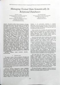
3. Modeling Object Behavior In this section, we discuss the mapping of state diagrams, expressing the life-cycle of objects of a given class, into database mechanisms, as found in the Entity-Relationship model [Chen76]. We briefly describe state diagrams, using a simple Flying Object state diagram example (see Figure 1). Then, based on this example, we describe the static and dynamic relational views of state diagrams. Next, we show how state diagrams are implemented using database mechanisms. Finally, we describe the integration of application classes with database objects.
3.1 State Diagrams A state diagram represents the life history of objects in a class and shows the sequence of operations that takes objects into several different states. It is a graph whose nodes are states of an object and whose arcs are
2
transitions between states caused by events applicable to that object. The graphical notation used for a state diagram is the Harel statecharts [Hare88]. Figure 1 shows a state diagram describing the life-cycle of Flying Objects. A Flying Object can be in the following states: AtRest, Taxiing, Taking Off, Flying and Landing. State diagrams can express, in relation to events objects can receive: • Transitions: represent state changes due to actions executed when objects of the class receive events. • Guards: describe the situations under which an object may accept an event. • Pre-conditions: describe what must be true after an event is accepted, but before its corresponding transition actions take place. • Actions: describe what must be executed when an event is accepted and its pre-conditions are true. • Post-conditions: describe what must be true after the actions corresponding to an accepted event are executed.
Time to TakeOff
ReachCruiseAltitude [NoTurbulence] / Activate Automatic Pilot
TakingOff
AtRest AbortTakingoff
Flying
EnginesOff
Landing
Taxiing
ApproachDestination (distance)
GroundTouch
Figure 1: Flying Object State Diagram As an example from Figure 1, when the event ReachCruiseAltitude produces a transition of flying objects from the TakingOff state to the Flying state, provided the pre-condition NoTurbulence is true. The corresponding actions include the activation of the automatic pilot.
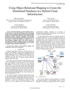
3.2 A Static View of State Diagrams In this paper, we represent the states of an object as first class objects. That is, states are treated as normal classes in the system and are represented as special subclasses of the object’s application class. This model allows the expression of behavior along several object attributes, each having its own state diagram; to each state diagram there corresponds a state-class hierarchy. This model also allows the nesting of states; nested states become subclasses of the nesting state-class. Figure 2 depicts a state-class hierarchy representing the life-cycle of flying objects. We basically use OMT notation [Rumbaugh+91], and show a few attributes in each class. State subclasses are indicated with a diagonal line across its upper left corner, as in Syntropy [Cook+94].
3
Flying Object id_FO Name Total Flying Hours automatic pilot
At Rest id_FO arrival date Next Flight
Taxiing
Taking Off id_FO Take off velocity landing strip turbulence
id_FO permission gate
Landing id_FO landing strip landing velocity
Flying Forward id_FO Crusing Height
Figure 2: Flying Object State-Class Hierarchy The static aspects of state-class hierarchies can be modeled using the mapping techniques proposed in [Keller97], where classes become tables and static relationships become attributes validated by database integrity constraints. The table corresponding to the root class of the hierarchy has as fields the attributes of the application class. Accordingly, each state-subclass becomes a table having as fields the specific attributes the object acquires when in that state. An identification attribute, created in each table (id_FO, in the example above), implements the association between state-subclass and application class instances.
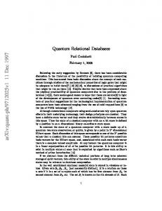
3.3 A Dynamic View of State Diagrams The tables mentioned above can be used to map object-oriented structure, in particular state attributes, to the relational world. To complete the paradigm shift, the dynamic aspects included in state diagrams must also be considered. Such aspects represent rules of behavior, which essentially drive state changes. We use a dynamic meta-model, shown in Figure 3 with E-R notation, to map object behavior in active relational databases. The different roles that a class may play in the system are represented as view type entities; The dynamic aspects governing state changes, such as events, transitions, pre- and post-conditions, are represented as entities in the E-R model; Pre- and post-conditions are implemented as conditions and actions in database triggers.
Simple Inheritance
V iew Type
Class Dynamic View Dynamic Characteristics
Event Initial State
Final
stimulus
State
source
State
destiny
V alid Transaction
Figure 3: Dynamic Meta-Model of State Diagrams
3.4 Implementing State Diagrams
4
In this section, we describe the implementation of state dependent behavior, as described above, as a threestep procedure: the creation of exclusion and inclusion triggers1, and the creation of stored procedures. Triggers correspond to state pre- and post-conditions, and stored procedures to transition actions. Step 1: Create triggers for transition pre-conditions. For each state-subclass representing a state originating a transition associated to a pre-condition, create an exclusion trigger. This trigger contains, in its body, statements verifying the pre-condition. To exemplify, consider the transition ReachCruiseAltitute from state TakingOff to Flying, in Figure 1 above. Its pre-condition is the absence of turbulence. The exclusion trigger below verifies this condition, and cancels the operation accordingly.
Create trigger Flying_I for insert on flying as update FlyingObject FO, set automaticPilot = “y” from FlyingObject FO, inserted I where FO.idfo = I.idfo; Step 2: Create triggers for transition post-conditions. For each state-subclass representing a destination state for a transition associated to a post-condition, create an inclusion trigger. This trigger contains, in its body, actions and statements verifying the post-condition. Again using the transition above, the action ActivateAutomaticPilot is verified by the inclusion trigger’s body:
Create trigger TakingOff_D for delete on TakingOff as begin Declare @var char(1); Select @var = (select turbulence State from deleted) If (@var = ‘y’) then begin raiserror ( “ Unable to transition to Flying “ ) rollback end for each event. Step 3: Create a stored procedure end For each event in the application domain, create a stored procedure, consisting essentially of the following code: 1. select all objects modeled by state-classes which originate transitions corresponding to the event received; 2. for each such object: • eliminate the object from the current state; • insert the object in a destination state.
1
We use the SYBASE SYSTEM XI T-SQL language trigger mechanism.
5
Note that the initial creation of an object with state dependent behavior results from two insertions: the first in its application-class table and the second in the state-class table corresponding to the initial state. Thus, when an object changes state, only the properties exclusive to the old state are lost.
3.5 Integrating Application Classes with Database Objects From the steps presented in sub-section 3.4, together with the dynamic meta-model expressed in Figure 3, one can envision the use of an active relational database as a tool for implementing object behavior . A positive aspect of this approach is that we reduce the complexity of object oriented applications, by reducing the amount of code necessary to enforce object dynamic behavior. In addition, the use of a database in the implementation of state transition diagrams, promotes low cost of application’s maintenance considering the facility of data updates in active relational databases. The integration between OO applications and the dynamic meta-model implemented over active relational database is presented in Figure 4, where the transition from the source state Takingoff to Flying is represented. The diagram comprehends the communication between the OO application and support classes and database management system objects, like tables, stored procedures and triggers. At the application side, we use the proposal in [Reese97, Silva97] where the Peer Pattern is used to separate the persistent behavior of an application domain class into a correspondent (i.e. peer) class. On the database side, the stored procedure execution engine, generalized here as DBMS, receives a request to execute the stored procedure which implements the actual transition. Its execution operates on the state subclasses related with the transition, implemented as tables in the database. In Figure 4, we show how the correspondent FlyingObject tuple is deleted from table TakingOff and inserted into table Flying. Both operations stimulate the correspondent triggers, which performs the necessary validation plus actions. OO Application
ReachCruise Altitude
Flying Object
Side
Persistent Flying Object
ReachCruiseAltitude
sp_reachcruise altitude
Active Relational Database Side
DBMS
TakingOff Delete
Insert
Flying
Check pre_cond Action
Check post_cond
Figure 4: Integrating of OO Application Classes with Active Relational Database Tables It is important to note that all the dynamic behavior is encapsulated into the active mechanisms of the database. Once an event is detected by the application its sole responsibility is to inform the database of such. It is of the latter the responsibility to proceed with pre- and post- conditions verification and actions execution, according to the dynamic behavior. The following Java classes exemplify the application code needed for the application domain side of the integration. The FlyingObject is a problem domain class with dynamic behavior as depicted in Figure 1. It’s response to events are expressed as the execution of the correspondent method, as is the case with the ReachCruiseAltitude method/event. The peer class PersistentFlyingObject is responsible for implementing the persistent behavior associated with the FlyingObject class. As seen in its body, the special treatments needed to execute the stored-procedure sp_reachCruiseAltitude link the OO application side with the database side. Public class FlyingObject { String name;
Int totalFlyingHours; Boolean automaticPilot; Boolean turbulenceState; Boolean ReachCruiseAltitude ( boolean turbulenceState) {
6
One can conceive that the whole dynamic behavior is being held by the active relational database. The transition validations, i.e. pre- and post- conditions, implemented over triggers, free the application programmers from enforcing them. The actions executed as part of the insert trigger, solves the indirection problem associated with the update of persistent data by the OO application, by reproducing cascading updates on the data in the database. By the end of the execution of the database side of the application, the transition has been executed, and validated, and the actions, if any, have updated persistent data. Now the situation points to the application objects which may need to be synchronized with the database. We are currently working to attend such a need.
4. Handling Object State Inheritance With the state model adopted in our approach, an application-class may have subclasses of two natures: application-subclasses, reflecting type relationships in the domain, and state-subclasses, reflecting dynamic behavior. We need to define precisely how an execution-time specialization of an application object, along its type hierarchy, affects its dynamic behavior, and also how this is understood in the active relational database where the object persists. Figure 5 depicts this situation, showing type and state inheritance for the FlyingObject example.
7
Fly ing O bject
H elicopter
Stoppe d on
Flying
Flying
Fly
B ack w a rds
Forw ard
Figure 5: Type Specialization from FlyingObject In this example, an Helicopter is a FlyingObject, inheriting via type specialization all attributes and behavior of a FlyingObject. Since a FlyingObject has state dependent behavior, as shown in Figure 2, this behavior is inherited by Helicopter. This means that objects of this class: • Respond to FlyingObject events, executing transition actions as defined in the FlyingObject class; • May refine FlyingObjects states producing subclasses states and consequently more detailed transitions; • May accept events specific to the Helicopter class, executing actions defined in this class; Figure 6 illustrates type and state hierarchies for FlyingObject and Helicopter. Flying Object Id_FO Name Object type Total Flying hours Automatic pilot FO state
At Rest Taxiing Taking off Landing
Flying
Helicopter Id_FO Number of blades Type of propeller Flying state
Stopped on Fly
Flying Backwards
Flying Forward
Figure 6: Combined Type and State Hierarchies A database view Helicopter_H corresponding to a join between the FlyingObject and Helicopter tables implements attribute inheritance. Helicopter_H objects are created according to both FlyingObject and Helicopter, and are retrieved as exemplified in the SQL2 section shown below.
8
CREATE VIEW Helicopter_H AS SELECT FO.Name,FO.Object_type,FO.Total_flying_hours,H.number_of_blades, H.Type of propeller FROM Flying Object FO, Helicopter H WHERE FO.id_FO = H.id_FO State-subclasses corresponding to the application-subclass (Helicopter, in the running example) can be either specialization of corresponding application-superclass states or new states, specific to the applicationsubclass. In the first case, by adopting nested states as in [Cook+94], we need to define the initial state for each view created in each class. A state transition may be represented in several levels in the application class type hierarchy. These transitions automatically occur from the execution of insertion triggers corresponding to destination states and exclusion triggers corresponding to origin states. Both types of triggers can be generated from the dynamic meta-model described in sub-section 3.3. The insertion triggers execute the following steps: 1. Verify the existence of subclasses of the application-class 2. For each sub-class specializing a view suffering a transition in the super-class, create a tuple in the table corresponding to the subclass’ initial state. For instance, let us assume that the initial state of the Helicopter view is FlyingForwards, as the transition according to this view is taken in FlyingObject, from the state TakingOff to the state Flying, actions corresponding to the same transition are taken in the Helicopter class. Exclusion triggers, as described above, execute similarly, eliminating tuples accordingly. For those states with sub-class specialization, transitions occur only in their most specialized level. The example below, where a FlyingObject specializes into a Helicopter, illustrates this situation. Consider the event PullBackStick in the example below, which causes Helicopter with id 10 to change states, from FlyingForwards to FlyingBackwards. The referred instance would accept the event by changing over the Helicopter sub-classes, while the instance corresponding to the super-class would remain untouched. obj1 : Flying Object id_FO: 10 name: esquilo-p13 object Type : Helicopter total Flying Hours: 10.000 automaticPilot : ‘N’ FO_state: flying Helicopter id_FO: 10 number of blades: 2 type of propeller: j2 When considering state sub-classes that are refined through more specific state sub-classes, one can benefit from the previous outline procedure by following the subsequent steps: 1. Represent sub-classes as specialization entities in the ER diagram; 2. Implement the sub-classes hierarchies as tables in the active relational database; 3. Represent the hierarchy structure as instances of the class self-relationship in the dynamic meta-model of
9
Figure 3; 4. For each accepted event over an object with dynamic behavior, consult the dynamic meta-model verifying the existence of more specific sub-classes and generate insert and delete triggers. It is important to note that, when executing a state transition, the delete operation over the source transition table stimulates a delete trigger which verifies the existence of the same object below in the state sub-class hierarchy, promoting its exclusion. The insert operation on the table representing the destination state of the transition, proceeds analogously.
5 Conclusion In this article, we presented a technique for integrating and implementing object behavior to active relational databases. In addition to using integrity constrains to check object static relationships between objects, our approach implements database dynamic constraints using triggers and stored procedures, to validate dynamic object behavior. We use state diagrams to represent dynamic object behavior and store them in the database. From the state diagram, we describe several steps to generate triggers and stored procedures. By using a peer pattern, we access the database executing a stored procedure any time an event causes an object to change states. When the stored procedure executes, insertion and deletion triggers simulates the object transition, validating pre and post conditions and executing actions that are specified in the state diagram. State inheritance has also been addressed, allowing the database to handle hierarchies of object behavior. The advantages of this approach are that both static and dynamic aspects of objects are integrated and mapped to the database. In addition, the amount of code to be written inside object methods is reduced, since any dynamic constraint validation for persistent objects is now done by the database. Moreover, maintenance is increased, considering the facility of data updates in active relational databases. Therefore, we believe our approach is well suited for the integration of object behavior with active relational databases, because of its simplicity and the ability to deal with the complexity of hierarchies of states. We are currently developing a CASE tool that will not only automate the generation of stored procedures and triggers that implement object behavior, but also maintain the object model synchronized with the database.
References [Chen76]
Chen, P., “The Entity-Relationship Model- Toward a unified model of data”, ACM. Transaction Database Systems, 1, March 1976;
[Chakravarthy +89] Chakravarthy, S., Blaustein,B., Buchman,A.P., Carey, M.J., Dayal, U., et all, “HIPAC: A research project in active, time constrined database management”, technical report XAIT-89-02, XEROX Advanced Information Technology, Cambridge. Massachusetts, july 1989; [Cook+94]
S. Cook, J. Daniels, Designing Object Systems: Object-Oriented Modelling with Syntropy, Prentice Hall, 1994.
[Gamma+95]
E. Gamma, R. Helm, R. Johnson, J. Vlissides, Design Patterns, Addison-Wesley, 1995
[Gargouri+94]
F. Gargouri, F. Biufarès, C. Ducateau, “Relational Implementation of Object Oriented Information Systems Design Using a Generic Model”, Proceedings of Object Oriented Information Systems, London, 1994, pgs 115-129
[Harel88]
D. Harel, “Statecharts: A Visual Formalism for Complex Systems”, Science Comput. Prog. 8, 1988, pgs 231-274
10
[Harel+96]
D. Harel, E. Gery, “Executable Object modeling with Statecharts”, Proceedings 18th International Conference on Software Engineering, 1996
[Kell96+]
W. Keller, and J. Coldewey, “Relational Database Access Layer,” In Pattern Languages of Programs (PloP), Monticello, Illinois, 1996.
[Keller97]
W. Keller, “Mapping Objects to Tables, A Pattern Language”, Proceedings of the 1997 European Pattern Languages of Programming Conference, Siemens Technical Report 120/SW1/FB, pp 59-84, Irsee, Germany, July 1997
[Reese97]
Reese,G., “Database Programming with JDBC and Java”, O’Relly, 1997
[Rumbaugh+91]
J. Rumbaugh, M. Blaha, W. Premerlani, F. Eddy, and W. Lorensen, Object Oriented Modeling and Design, Prentice-Hall, Englewood Cliffs, 1991.
[Schlaer+90]
S. Schlaer, S. Mellor. Object Life Cycles: Modeling the World in States. Yourdon Press, 1990
[Silva+97]
M. J. Vianna e Silva, S. Carvalho, J. Kapson, “Patterns for Layered Object-Oriented Applications”, Proceedings of the 1997 European Pattern Languages of Programming Conference, Siemens Technical Report 120/SW1/FB, pp 85-94, Irsee, Germany, July 1997.
[Teisseire+94]
M. Teisseire, P. Poncelet, R. Cicchetti, “Towards Event-Driven Modeling for Database Design”, VLDB Conference Santiago, Chile, 1994 ,pg. 285-296
[Widom+96]
J. Widom , S. Ceri, “Active Database Systems: Triggers and Rules for Advanced Database Processing”, Morgan Kaufman, 1996
11