1
Object-Oriented and Cooperative Process Modelling in EPOS Reidar Conradi1 , Marianne Hagaseth, Jens-Otto Larsen, Minh Ngoc Nguyên, Bjørn P. Munch, Per H. Westby, Weicheng Zhu, Norwegian Institute of Technology (NTH), Trondheim, Norway M. Letizia Jaccheri, Politecnico di Torino, Italy Chunnian Liu, Beijing Polytechnic University, Beijing, P.R. China Submitted for PROMOTER Book 1994 (ed. Bashar A. Nuseibeh, Imperial College) Abstract EPOS2 is a kernel Software Engineering Environment. It has emphasis on Process Modelling, based on object-oriented principles and on cooperating transactions against a uniformly versioned EPOSDB. EPOS-PM relies on the SPELL process modelling language. This extends the underlying EPOSDB data model with full object-orientation, type-level properties, tasking, and meta-types to allow reflection. SPELL can be used to model, plan, execute, and evolve software activities; and associated products, tools, human roles, and projects. The SPELL types in a Process Schema can be customised through subtyping and evolved in project-specific, versioned sub-databases.
1. Detailed address: Dept. of Computer Systems and Telematics, NTH, N-7034 Trondheim, Norway. Phone: +47 73 593444, Fax: +47 73 594466, Email:
[email protected]. 2. EPOS, Expert System for Program and (“Og” in Norwegian) System Development, was supported by the Royal Norwegian Council for Scientific and Industrial Research (NTNF) through grant ED0224.18457. Do not confuse with the German real-time environment EPOS [Lem86], or with Extended Prolog for Order-Sorted resolution etc.
2 EPOS-PM is implemented by a Schema Manager, a SPELL Interpreter, an Execution Manager, a Planner to incrementally (re-)construct activity networks, and various Project-related tools to plan and implement project breakdown and cooperation. All these process tools are instrumented by SPELL types. The EPOSDB features a version part with ChangeOriented Versioning and a product part through a data model with structural object-orientation. EPOSDB also offers long, cooperating and nested transactions through a client-server architecture, with a version-transparent interface. Inter-transaction negotiation and propagation is regulated by communication protocols defined and managed by EPOS-PM, using EPOSDB mechanisms. A Broadcast Message Server is used to connect EPOSPM to external tools. The paper also summarises the experience so far, and discusses future work.
Keywords: Software Process Modeling, Software Engineering Environment, Object-Orientation, Versioned Database, Model Evolution.
1 Introduction The importance of the software process to ensure software quality and productivity has been given wide-spread attention recently [PCC91] [BL79]. To give effective support for software production processes, the relevant work patterns of a company or project should be explicitly modelled, guided (sometimes enforced), reasoned about – and allowed to change. Process modelling (PM) assumes suitable modelling language(s), methods and tools. Since PM is applied to domains with a high degree of human-human and human-machine interaction, there is a need for highly customisable and evolving process models. This often implies a reflective modelling language and tool architecture. No PM support system can be used for real-world, software projects without connection to a versioned DBMS, and its associated Configuration Management (CM) support system [Tic88]. Similarly, an effective CM system assumes suitable PM
3 support to manage the versioned software production activities. Both the PM and CM support should be open-ended to accommodate domain-specific products, tools, and work patterns – all represented as process models. However, several integrated CASE tools and many CM systems have implicit and hardwired process models to express design and change activities. Recent tool architectures try to acknowledge “process” as an independent integration axis, in addition to database (DB), user and control integration [ECM90]. Although the emphasis in this paper is on software PM and partly on CM, the results should be applicable to office automation, CAD/CAM (with concurrent engineering), VLSI etc. The ensuing sections of this paper are as follows: First, some PM concepts are commented in the remainder of this section. Section 2 gives an overview of the rationale behind EPOS-PM, the EPOS architecture, and the EPOS meta-process. Section 3 elaborates the details of EPOS-PM, with emphasis on the SPELL Process Modelling Language and the tools to support it, and on the facilities for type evolution. The EPOSDB versioning and transaction model, cooperative transactions, and project planning support are presented in Section 4.3. Section 5 discusses an example. Section 6 describes implementation status and preliminary experience, The final Section 7 contains a conclusion with suggestions for further work.
A Remark on Terminology We will use process model to denote the internal computer representation of an external process (or application), be it software production or banking. However, several researchers use “process model” only for what we will call a Process Schema (types, templates, rules), see also [CFFS92] [FH93] [Lon93]. A software process is the set of software engineering activities and associated information needed to transform a user’s requirements into functioning software. The process elements1 include activities and their associated products and dependencies, application tools, human roles and users, organisations and (sub)projects. All this is guided by rules and policies (static or dynamic), standards, and development methods. The process model contains process model fragments to represent such elements. Some of these fragments are organised in a Process Schema, often being a typed description of a class of such elements. The underlying Process Modelling Language (PML) and process tools are implemented by a Process Support Environment (PSE). Process tools that structurally change (e.g. contructs) the process model are called meta-tools.
1. These include most of the information normally stored in a Software Engineering Environment.
4
2 EPOS Summary 2.1 EPOS-PM: Rationale and Overview As mentioned, a PSE is intended to operate in a human-oriented system [CFFS92]. Its overall control and planning facilities should therefore serve as an intelligent and cooperative assistant (proscription), not as a strait-jacketing controller (prescription). A perpetual argument has been human creativity vs. automation [Leh87], or support versus control. Thus, evolution (refinement, customisation, and revision) of the Process Schema and its instances is crucial during the process life-cycle.
Powerful process modelling Our goal has been a generic, flexible, system-interpretable PML to describe common process elements. The actual PML should adequately describe the main categories of process elements. Specially the activities must be modelled with sufficient ease and precision. There are five ways (previously called “PM paradigms” [LC91]) to express these: rules (i.e. production rules) like in MARVEL [BK92], MERLIN [PSW92], OIKOS [ACM90], or ALF [B+89]; database triggers (Event-Condition-Action rules) like in ADELE [BEM93]; activity networks like in MELMAC/MSP [DG90] and SPADE [BF93] both using generalised PetriNets; process programs like in ARCADIA [TBC+88] and IPSE 2.5 [War89]; or hybrids like EPOS. The EPOS PML, SPELL [COWL91] [C+92], has chosen the hybrid paradigm, like most PMLs. The internal process model local to a transaction is basically a typed network of chained and decomposed activity descriptions (tasks). These are linked to descriptions of other activities, products, tools, and roles. The activities interact with each other, and with tools and humans. A task type in SPELL expresses knowledge about a development step/ tool, and constitutes an activation rule with a program (script) to be executed. It defines static and dynamic PRE- and POST-conditions around a CODE part, and serves as a tool signature or envelope. Static PRE- and POST-conditions are exploited for forward or backward reasoning without executing the CODE. Dynamic PRE- and POST-conditions are convenient for dynamic triggering of tasks, see below. A task instance (in short: a task) is potentially active, and stands in a task network1 or plan. The network uses product nodes to “connect” neighbor task nodes, and it can partially be automatically generated. FORMALS and DECOMPOSITION type constructors (static constraints expressing a graph grammar) and static PRE/POSTconditions regulate the structure and control flow of the task network. Task execution can take place at any task node, not only at the leaves. Network 1. Being intra-transaction ones, see below for inter-transaction networks.
5 control-flow can be busy (triggered), periodic, opportunistic, or lazy (goal-oriented like Unix make). Task execution can be automatic (derivative) or manual (human actor), with arbitrary review or negotiation procedures. A task’s sequential CODE part is responsible for causing its dynamic POST-condition to become True. This may cause dynamic PRE-conditions in other tasks to become True etc.. The CODE of a task may re-execute, repeating the pattern above. It will typically execute procedures defined by the types of its input and output “parameters” (preceding and succeeding product nodes). It is not easy to determine the boundary between a production rule in an active task and a database trigger/ procedure associated to a passive product object. We can say that the latter represent more fine-grained and short-lived operations, while certain tasks may be decomposed and run for weeks.
Simple and well-structured modelling We have chosen a fully object-oriented approach, covering all categories of process elements. A Process Schema in EPOS then contains a set of types. Further, we have the following kinds of rules: •
Meta-rules (in meta-types) expressing general information/constraints and policies for the domain in question, as well as heuristics for planning.
•
Static rules describing tool signatures, and static consistency constraints in general.
•
Dynamic rule expressing non-temporal (dynamic consistency) conditions.
•
Dynamic rules expressing temporal conditions such as policy for when to recompile (lazy, busy, ...), and reasoning about time stamps for recompilation. The rule-structuring formalism and its binding mechanisms will strongly influence our ability to evolve and customise rules, or any meta-level information. Due to subtyping and (versioned) subprojects, the EPOS rule base is basically hierarchically organised. We are investigating how to better structure the EPOS rule/task base, e.g. by using sub-schemas or other encapsulation mechanisms. However, there is tool support for navigating in the library of available types.
Persistency and versioning The process model must be persistently stored, and at least the product part must offer versioning. The EPOS process model fragments are meta-types, types, and instances of entity or relation types. The underlying EPOSDB offers uniform versioning of all this in a transaction context. Each database (sub)transaction is connected to a (sub)project task, standing in a global task hierarchy. Between such decomposed projects/transactions there is a “horizontal” inter-transaction task network, where information exchange is regulated by communication protocols. In addition comes the above-mentioned intra-
6 transaction task networks to express local and possibly decomposed development steps like develop, edit, compile etc. – and control flow between these. EPOS-CM (versioning, data modelling) and EPOS-PM go hand in hand: EPOSCM exploits EPOS-PM to control and perform changes to evolving products. Inversely, the process model is itself a structured and evolving “product”, under EPOS-CM control.
Support for customisation and evolution For a summary on how some of the previously mentioned PSEs manage evolution and customisation of their PM support, see [JC93]. Evolution of process models in EPOS occurs along two axes. Vertical evolution is done by object-oriented subtyping (by t_create meta-procedure in Section 3.2.4), and subproject refinement (in subtransactions). Horizontal evolution is done by customisation and versioning between projects (e.g. by t_change meta-procedure in Section 3.2.4), and by incremental (re)construction of task networks by a Planner.
Reflective architecture Since evolution of all process fragments is pervasive, a reflective PML is required. SPELL uses meta-types to achieve this, where meta-procedures control the evolution of the Process Schema. There is also automatic support for local task network (re)construction (see the Planner [Liu93]) and for setting up global subproject networks (see Project Manager). SPADE has a similar local network builder, based on reflective PetriNets [BFG93].
Cooperation Many published PSEs are single-version or even single-user. and the support for cooperation is slight. Processes include many human actors, and they need to cooperate and exchange data in a structured framework. EPOS offers support for this through overlapping, cooperating transactions with mutual cooperation protocols.
Methodology support The meta-process of making and evolving a process model can be explicitly modelled, although there is little high-level support for this.
Standard architecture and implementation EPOS offers a client-server architecture through its EPOSDB, and is kept separate from production tools through a Broadcast Message Server (BMS). EPOS is implemented by standard technologies such as Unix, the X Window System, C, and Prolog.
7
2.2 The EPOS meta-process We can very coarsely identify six life-cycle phases or meta-activities for process models in EPOS, taken from [CFF93] but differing from [FH93]. These meta-activities constitute the meta-process, and must be supported by appropriate methods, formalisms and tools. The process tools will be briefly described in this subsection and the next on EPOS architecture (2.3), and more thorough in Section 3 on EPOSPM and in Section 4 on EPOSDB. The six EPOS meta-activities are [JC93]: (1)
PM0. Provide a PSE containing: a PM methodology, a Process Modelling Language (PML), libraries of reusable process models expressed in the PML, and process tools for acquisition, modelling, analysis, evolution, execution, monitoring etc. of process models. PM0 consists of SPELL, EPOSDB, and EPOS process tools mentioned below.
(2)
PM1. Elicit requirements for an informal process model. This is done with input from the application domain(s). PM1 has no tool support in EPOS.
(3)
PM2. Analyse/design1 a template model, i.e. a formal Process Schema (“symbolic program”). The Process Schema can be generic, which can be adapted and transformed into a more specific for the actual project. This meta-activity includes browsing, editing, and analysing a library of reusable model fragments (often types). PM2 is supported by the Schema Manager meta-tool.
(4)
PM3. Implement/instantiate an enactable model (“load image”). E.g. enactable activity (sub)networks are made according to the actual products, schedules, tools, and human resources. PM3 is supported by the folowing meta-tools: Planner, Project Manager, Cooperation Manager, Workspace Manager, and some extractor and editor tools to handle product models.
(5)
PM4. Execute2 an enacting model (“running image”). Execution mainly consists of guided or enforced use of application tools. PM4 will interpret information set up in PM3, and also “run” the PM3 metatools. This meta-activity is supported by the EPOS Process Engine, being the 1. In [CFF93] these meta-activities were split. 2. Enact has often been used to cover both automatic and manual interpretation and execution.
8 SPELL Interpreter and the Execution Manager for task networks. The latter is connected to a BMS. (6)
PM5. Monitor and assess external process performance, with feedbacks to PM0–PM4. This goes in parallel with PM4 on execution.
EPOS has no other tool support here than the above PM2–PM4 tools. In addition comes human observation and intervention. We might have added Evolution as a PM6, but change is an underlying and pervasive assumption in all the above meta-activities. Further, there is no assumption that PM1–PM5 should be done in a strict “waterfall” sequence for all parts of the model. Further, not every PSE allows the distinction or formalisation of all these meta-activities. Since EPOS has dynamic/late binding of process “parameters” and incremental instantiation of enactable process models, the distinction between template, enactable (instantiated) and enacting models is blurred. That is, definition and evolution of process models is an incremental and never-ending meta-process. We may add, that proper access control of course is needed.
2.3 The Layered EPOS Architecture PSEs that rely on an object-oriented database, e.g. PMDB [PS91] and ADELE, often have a PML as a layer around the underlying database. EPOS extends this by having three layers around the database. The EPOS layers are: 1. EPOSDB: a client-server DBMS offering uniform, change-oriented versioning (4.1) and a structurally object-oriented data model ( 3.1 ). It has a simple DDL and a free-standing DML, both in Prolog. Long, nested and cooperating transaction (4.3 ), defines a uni-version context for database access. A transaction is connected to a file-based workspace, through check-out/in. 2. A reflective and fully object-oriented PML, called SPELL, that unifies and extends the underlying DDL/DML. This EPOS layer supports meta-activities Analysis/Design (meta-activity PM2) through the Schema Manager process tool ( 3.2.4 ), and Execution (PM4) through the SPELL Interpreter ( 3.2.1 ). 3. A Tasking Framework for definition and concurrent execution of task networks, with associated tools and humans. Execution (meta-activity PM4) is done by one Execution Manager ( 3.2.2 ) per transaction, with communication to external tools through a BMS. The Execution Manager interprets information defined in a predefined TaskEntity type (Figure 3). The Tasking Framework also partially supports meta-activity PM3 through a
9
EPOSDB, with subtransactions
PROCESS TOOLS:
Parent project/transaction
Meta−types PRE... CODE... POST...
Types
Internal process model in EPOSDB:
Instances Task network:
Child−1
Child−2 Coop.
Meta−types ...
Meta−types ...
Types ...
Types ...
Instances ...
Instances ...
S P EE PL OL S DI BN T DE DR L P / R DR ME L T E R
Schema Manager
Execution Manager, Planner, Project Manager
Cooperation Manager
Workspace Manager
Tool calls Filter Check−out/in
Messages
Check−out/in
BMS
Project−2
Project−1 Tools
External process, i.e. an application with file−based workspaces:
Persons
Files−1
Files−2
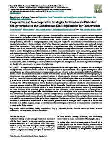
Figure 1 EPOS architecture – EPOSDB, process tools, and internal process model (data structures) to describe the external application. Planner ( 3.2.3 ), that incrementally (re)instantiates task networks. Project management and inter-project communication are supported by more global process tools in meta-activity PM3, see Section 4. 4. Application- or domain-specific process models. They include both Process Schemas, e.g. task types, and their instances, e.g. activations of production tools. Application-specific types is used to instrument process tools like the Schema Manager, Execution Manager, and Planner with domain knowledge. All activities (“PM”-data) and products (“CM”-data) in the application are described through the same SPELL PML, and will be connected by relationships. The product model for EPOS-CM is described in Figure 2. This application layer has special process tools (extractors, editors) to define e.g. product structures (meta-activity PM3), not dealt with further. The overall EPOS architecture is shown in Figure 1. An example of an internal
10 process model, organised in subprojects (subtransactions), is also shown.
3 EPOS-PM support EPOS-PM will be presented in two main parts. The first is about the SPELL persistent object-oriented language used to model software processes and the products they change. The second part presents the EPOS (meta-)process tools which cover meta-activities PM2–PM4 of the software process lifecycle.
3.1 The SPELL Language SPELL supports several levels of abstraction and composition to model the external process elements [C+92].
Types and Model Structuring Figure 2 displays some system-defined and predefined types, showing the same layering as in Section 2.3. The underlying EPOSDB has a data model close to the object-relation model suggested by [Rum87]. Entities (objects) have unique and immutable identity. There is a system-defined Entity root type, with a TypeDescriptor metatype. There is also a Longfield type for storing arbitrary files, not shown. SPELL in addition supports definition of types with both an instance-level and a type-level part. That is, it offers type-level attributes and instance/type-level procedures and triggers. Meta-types are used reflectively as in Smalltalk [GR83] to store type-level information, although the meta-types are manually created and used. Type-level relations are explicitly modeled and can be used to model subtyping, or some internal relations that encode e.g. the FORMALS and DECOMPOSITION type constructors. There is a spesialised PM_Entity subtype, with TaskEntity and DataEntity subtypes (see later for both). The meta-types of the latter two are TaskDescriptor and DataDescriptor, respectively.
Inheritance and Protection Single inheritance with dynamic binding is provided for all type properties (attributes, procedures, triggers). A subtype may redefine type-level attributes and instance/type-level procedures. Three kinds of inheritance are available for typelevel properties and for procedures: redefine (overwriting – the default), append (logical conjunction), and concatenate (the Simula inner mechanism [DMN70]). Redefined procedures in a subtype may be inherited by either redefine or concatenate. Attributes and procedures can be declared private or public (not shown).
11 Entity
EPOSDB types
TypeDescriptor
SPELL OO extensions
PM_Entity
TaskDescriptor
GenInputs
DataDescriptor TaskEntity
Project
Develop
DataEntity
Compile
GenOutputs SubTasks
Part
DependsOn
Design ImplementedBy
Component
Family
Tasking Framework
Application− specific types
InterfaceOf
Composition DesignDoc
Executable
ObjectCode
SourceCode
Interface
FamilyOf
Body
Figure 2 The EPOS Types.
The TaskEntity type A simplified definition of this basic task type is presented in Figure 3. The attributes have domains like String and Pred(icate). As mentioned in Section 2.1, a task has many type-level attributes to control its static and dynamic behaviour – e.g. PRE, CODE, POST, FORMALS, and DECOMPOSITION. These will be elaborated in the next subsection 3.2 on process tools. Task subtypes (e.g. Design and Compile) with empty DECOMPOSITION encode low-level or atomic tools. Task subtypes (e.g. Project and Develop) with non-empty DECOMPOSITION encode more high-level activities, whose main work is delegated to their generated subtasks. Relevant relation types are SubTasks to express task instance decomposition, and GenInputs and GenOutputs to link a task instance to its actual input/output parameters being product descriptions.
Predefined Product Model types (simplified) The DataEntity subtypes and corresponding relation types in Figure 2 express our Product Model Schema. It is inspired by the corresponding schema in Adele [BEM91], and is not oriented towards any specific development method or pro-
12 ENTITY_TYPE TaskEntity:Entity { INSTANCE_LEVEL ATTRIBUTES Exec-state: ... := ...; Taskstate: String := ’Created’; PROCEDURES
% For task implementation. % Similarly. % See under Schema Manager, Sec. 3.2.4.
i_convert(SelfO:OID, NewT:TID) = ...; i_delete(SelfO:OID) = ...; start(SelfO:OID) = ...; restart(SelfO:OID) = ...; stop(SelfO:OID) = ...; TRIGGERS ON-PROC = ... WHEN = AFTER COND = ... ACTION = ... TYPE_LEVEL ATTRIBUTES PRE_STATIC (Inher=append) Pred = true PRE_DYNAMIC(Inher=append) Pred = true CODE (Inher=concatenate) Prog = ... INNER ... POST_STATIC (Inher=append) Pred = true POST_DYNAMIC(Inher=append) Pred = true FORMALS (Inher=redef) String = ’in:$DataEntity(read) ⇒ out:$DataEntity(read/write)’ DECOMPOSITION(Inher=redef) String = ’REPERTOIRE(TaskEntity)’ EXECUTOR (Inher=redef) String = ’’ ROLE (Inher=redef) String = ’’ PROCEDURES t_create(SelfT:TID, ChildT:TID, )= ...; % Called by Schema Manager. t_delete(SelfT:TID)= ...; % See Schema Manager. t_change(...)= ...; % Same parameters as t_create. i_create(SelfT:TID)= ...; % Normal NEW generator.
subgoals(...)= ...;
% Subtyped, used by Planner in Sec. 3.2.3.
} % TaskEntity-type Figure 3 The TaskEntity type gramming language, cf. MILs [NS87]. The type Part is used to describe any software part. A Family subtype describes a general collection of subsystems (a directory, a library), as well as a single module. A FamilyOf relation type, being a subtype of Composition, links together Familys. Another Component subtype of Part represents atomic parts of software products. It has subtypes to denote different contents, file formats etc.. Instances of these types are related to LongField instances, that store the real contents of the software parts.
13 Interface and Body are indirect Component subtypes, connected by an ImplementedBy relation type. The DependsOn relation type connects two arbitrary Component subtypes.
3.2 The Process Tools The following four EPOS process tools are described in this subsection: SPELL Interpreter, Execution Manager, Planner, and Schema Manager. As mentioned, the two former constitute the EPOS Process Engine. The two latter are meta-tools, i.e. changing the process model. The remaining three process meta-tools are the Project Manager ( 4.7) with its Transaction Planning Assistant ( 4.8), the Cooperation Manager ( 4.6 ), and the Workspace Manager ( 4.5 ). They will be described in Section 4 on cooperating transactions. No sophisticated or well-coordinated User Interface is attempted among these tools.
3.2.1
The SPELL Interpreter: call_proc
The access and dynamic binding of procedures and attributes, both instance- and type-level, is implemented by the SPELL Interpreter. This consists of one Prolog predicate1 (PM4): call_proc(?Caller,+Called,+Procedure_Name, +Input_Parameters,-Output_Parameters).
The predefined DML procedures read, write, read_relation, and write_relation are used as procedure parameters for accessing both instance- and type-level attributes, e.g.: call_proc (?Caller, +Called, read, % For entities. +Attribute_Name, -Attribute_Value). call_proc (?Caller, -Called, read_relation, % For rel.entities. +Relation_Name, -Relation_Item).
3.2.2
The Execution Manager
Tasking is realised by the Execution Manager (PM4) that utilises three type-level attributes: •
PRE_DYNAMIC, specifying the condition on when to execute an instance of the given task type. It may have side-effects, e.g. to read a mailbox. The condition is combined with local task information about task state, and goal-directed (on 1. In the specification of Prolog procedures, parameters prefixed by ? are optionals, by + are mandatory input parameters, and by - are output parameters.
14 demand) vs. opportunistic execution (eagerly). •
CODE, being a sequential program to perform the intended job of the given task type. Thus, execution of a task means interpretation of its CODE. For an atomic task type like Compile, the CODE contains all the relevant actions. For a composite or high-level task type like Develop, the middle part of CODE is empty, causing the Planner to be invoked to instantiate subtasks.
• POST_DYNAMIC, e.g. to treat errors. The Execution Manager also maintains the instance-level attribute TaskState (Figure 3), whose value domain is: Created during Planner instantiation, Waiting on its PRE_DYNAMIC condition, Active during CODE execution, or Terminated. The type-level attribute EXECUTOR refers to the logical name of the tool that should execute the task, while ROLE refers to a generic human actor, e.g. a software developer. As mentioned, the communication with external tools go via a BMS. A special filter tool against EPOS converts message formats and identify senders/receivers. EPOS is not aware of how such external tools are activated, and neither are the external tools about their activators. However, such tools must consistently be described both as BMS table entries and as EPOS types.
3.2.3
The Planner
The Planner [Liu91] meta-tool is technically a procedure in meta-activity PM3. It is implicitly and incrementally invoked by the Execution Manager (PM4) to detail composite tasks, as indicated above. That is, the Planner will automatically generate a new subtask network for such tasks – and so on in due time. In practise, the Planner is mostly used to generate the subtasks of Project, Develop, and CooperationManager tasks. See examples later, using the task and product types explained above. The Planner starts with a composable Task and its desired Output – the goal. It applies backward chaining and hierarchical decomposition, combined with domain-specific knowledge, to build a proper subtask network (a plan in AI terms). The planning is based on the Process Schema as a Knowledge Base (KB), and a representation/model of the Product Structure (PS) as a World State Description (WSD) [Liu91]. There are two layers in the Planner. The inner layer or core of the Planner is a domain-independent, AI non-linear planning algorithm, resembling that in TWEAK [Cha87] and IPEM [AIS88]. The integration of planning, execution and monitoring is at a coarse level through hierarchical planning. The generated plan (a task network) satisfies the basic requirement: Every pre-condition of every node (task) in the plan is matched by a post-condition of another node. Otherwise, the
15 plan is not completed, and the planning process continues. The outer layer of the Planner is domain-specific to PM. It transforms certain type-level attributes of task types (PRE/POST_STATIC and FORMALS) into AI pre/post-conditions of nodes, so the core layer can work. This transformation also considers the PS, cf. the subgoals procedure in TaskEntity and further subtyping of this. The Planner utilises four additional type-level attributes: •
PRE_STATIC and POST_STATIC express necessary conditions that must hold, respectively, before and after execution of a task of the given task type. They are assumed not have side-effects to guarantee “clean” reasoning.
•
FORMALS, divided in FORMALS_IN and FORMALS_OUT by the ‘=>’ delimiter, specifies the legal “product” types of actual parameters (Inputs/Outputs) of the given task type. “$” means a list of parameters and read/write refers to allowed data access.
•
DECOMPOSITION specifies an unordered pool of candidate task types for subtasks of the given composite task. Note: An empty middle part in CODE assumes a non-empty DECOMP. None of the above attributes are supposed to have any side-effects upon (re)evaluation, thus facilitating goal-oriented reasoning. Clearly, changes to these schema attributes and to the product structure imply replanning. An incremental algorithm for replanning is presented in [Liu93].
3.2.4
Schema Manager
The Schema Manager [JLC92] meta-tool is responsible to browse, edit, translate, and generally manage the set of types. It was originally developed in a student project called BEATE, and offers a graphical user interface. The type-level procedures t_create, t_change, and t_delete are used to manipulate the Process Schema. This happens during the PM2-Design while customising the Schema, and later during PM4-Execution for corrections and supplements. These procedures are often subtyped, and initially defined in the Entity type. Type changes can have a profound effect on its instances, and on instances of related types. The feasibility of a requested type change must be evaluated against its possible impact on the whole Process Schema and its instances. A set of consistency constraints in the local Project type will be consulted [JC93]. If the impact is too big, a new subtype might be defined, so that only a subset of the instances of the old type will be affected. Type changes are termed hard (but simple), if they involve changes in definitions of instance-level attributes or “type surgery” on the type hierarchy. Hard type changes are allowed to some degree in EPOS, using the i_convert procedure to convert some of the old instances. This usually involves delicate human interven-
16 tion, see [JLC92] on aspects of this. Type changes can also be soft or behavioural (and complex). These involve changing procedures/triggers or type-level attributes. Although such type changes easily can be implemented in SPELL, they may have big consequences for the Execution Manager and Planner, and there are delicate synchronisation issues here. E.g. the Execution Manager should not allow changing the CODE script of active tasks.
Procedure t_create Procedure t_create implements parts of meta-activity PM2 concerning the Schema. The Schema Manager invokes the t_create of the given supertype, with its meta- and type properties as parameters. The definition of a new subtype cannot, of course, affect the definitions of existing types.
Procedure t_change Procedure t_change attempts to update procedures or type-level attributes of a type, and has the same parameters as t_create. All the instances of the old type are implicitly converted to be instances of the modified type. As mentioned, the Planner and the Execution Manager rely on type-level attributes, whose changes may lead to inconsistent situations. The procedure t_change is in charge of evaluating the impact of the proposed change and to find the necessary actions to put the system back to a consistent state. However, as the proposed actions may have a deep impact, a dialog is started with the user who may choose not to carry out all the proposed actions, or even to cancel the change-request.
4 EPOSDB: Uniform Versioning and Cooperating Transactions This section discusses the versioning model of EPOSDB, transactions and workspaces, overlapping transactions, workspace control, low-level propagation protocols, the project context, and more high-level support for “planning” of subtransactions. An initial observation is that EPOSDB has an internal architecture where the data model ( 3.1 ), versioning model ( 4.1 ), and transaction model ( 4.3 ) are separated into three distinct layers. This promotes a clean and orthogonal structure for both modelling, design, and implementation of the EPOSDB.
4.1 Change-Oriented Versioning EPOSDB [Mun93] implements Change-Oriented Versioning (COV) [Hol88,L+89,-
17 MLG+93]. COV considers a set of physical changes to a set of database fragments as one logical (or functional) change. COV is largely independent of the data model, and enables uniform versioning of entities and relationships, including schema-level information. In COV, a version is not an explicit object, but can be evaluated as a combination of the selected changes (deltas). It applies to any granularity: atomic objects, subsystems, configurations, or entire databases. Traditional versioning models use a version tree/graph for each versioned object, thus creating a version group of “similar” objects. However, making version selections that combine (merge) changes done at different “parts” (branches) in the version tree is not automatic. In COV, the changes have no “history”, and can in principle be freely combined. A logical change is described by a boolean option. Logical changes can be freely combined, possibly constrained by stored version-rules (predicates). Options are global: an option may be used by different users, and an option may involve changes to more than one component. However, it is not necessary that all components be affected by every option. In a version selection in COV, we must first specify an option binding of true/false values for the relevant options. This binding is called a version-choice, and will select the visible version of the entire database. Then a selection in the product space can be done. This is the inverse binding sequence of that in most other CM systems, although ADELE has an intermixed product/version binding sequence. Changes are carried out in a long transaction. A transaction is characterised by an ambition which may have unbound value-settings for options, thus specifying a set of potential versions to be affected. The ambition defines the intended scope of the changes: if an option is left unspecified, the changes will be visible independently of which value this option is given in later version-choices. Thus, we can say that the version-choice regulates the reading from the DB, and the ambition the writing back to the DB. The version-choice must include all true or false option bindings of the corresponding ambition. If ongoing transactions have overlapping ambitions and sub-products, we should encourage such sibling transactions to cooperate, to avoid merges afterwards or even loss of information by over-write or rollback. In spite of many similarities between COV and traditional versioning, there are important differences. COV offers: •
Intentional and flexible version selection based on logical changes,
•
Explicit representation of the version space (e.g. for locking), and
• Versioning being orthogonal to the stored data and its granularity. A version-rule can be a constraint, a preference, or a default, all used for guiding or restricting setting of ambitions and version-choices. Status properties can be asso-
18 ciated with versions, ranging from “untested” to “released-and-frozen”.
4.2 Configuration Description and Evaluation in EPOSDB A configuration is described by a database query or intentional config-description, CD = [VD, PD]. The VD or version-description consists of a partially bound version binding. The PD or product-description contains a read-set intentionally expressed as a query like [Root objects, ent/rel-types], and an extensional write-set expressed as [objects]. A bound configuration, a Config, can then be expressed as Config := Evaluate-config(CD, DB). The evaluation goes in three mapping steps, plus a step to prepare the workspace: •
C1) (A,VC) := Bind-version(VD, version-rules). That is, the more high-level and partially bound VD is evaluated to a low-level ambition A and a completely bound version-choice VC. The mapping may change as the version-rules evolve [GKY91].
•
C2) Sub-DB := Version-select(VC, DB). This mapping creates a single-version view of the database, implicitly doing a raw merge of several previous changes where appropriate. The ambition A is used when committing the Sub-DB.
•
C3) Config := Product-select(PD, Sub-DB). This mapping selects a Product Structure or configuration, by constraining the bound sub-DB through a transitive closure (Section 4.8 ). The mapping may change, due to structural changes in the product (really a C2 change).
•
C4) Workspace = Check-out(Config, DB-WS map). This fourth step will generate a workspace, mostly file-based.
4.3 Transactions and Workspaces Transactions EPOSDB offers long (non-serialisable) and nested transactions with checked-out workspaces. However, some form of traditional “ACID” transactions can be added, and may be needed to “atomise” internal EPOSDB operations. Transactions may survive several application sessions. They may be connected to Project tasks, but can also exist independently. The transactions may be started, committed or aborted interactively. All database operations must be performed in a
19 given transaction context, where they operate on a chosen database version “slice”, i.e. the visible sub-database. The transaction also specifies the scope (called ambition, see Section 4.1) of the local changes. A nested, child transaction overlaps and possibly constrains that of its parent, and possibly overlaps that of its siblings. This implies write locks of version subspaces (sub-DBs) and access to only to product subspaces (sub-products) within these versions. However, we are not constraining access to whole instances, only to versions of these instances. After child commit, changes are propagated to the parent, which must handle possible update conflicts. We should therefore prepare later merging by pre-commit negotiation and propagation between parent and children. These are the classic PM issues.
Workspaces A subset of a bound sub-DB, a configuration, can be checked-out into and checkedin from “DB-external” and possibly distributed workspaces with special data representations. This allows easy access by conventional tools, and corresponds to the classic copy-modify-merge paradigm. A single-version workspace in EPOS typically has three parts: •
The Project Knowledge Base, as Prolog facts. This comprises the relevant task types, and project infrastructure like communication protocols, Roles, Persons etc..
•
Task and product structures, also as Prolog facts.
•
File system structures (e.g. obtained from long fields), representing a selected version of a particular subsystem in the real database. Note, that start and commit of a transaction embeds check-in and check-out of workspaces.
4.4 Cooperating Transactions with Partial Overlap As mentioned, a transaction has a scope, an ambition. This may leave some options unbound1, and may thus identify a potentially large set of versions or configurations, where changes from the current transaction will be visible after commit. Transactions with overlapping ambitions and product structures to the current one are candidates for reevaluation after commit of the latter. These configurations may be ongoing, i.e. we need cooperating transactions. They may also be finished (“released”), i.e. we should notify their responsibles for possible reevaluation. 1. In fact, it may bind only one or a few options.
20 There are two kinds of overlap, cf. previous C1- and C3-mappings ( 4.1 ): •
Version-overlap: mutual version visibility. Two ambitions are overlapping, if no option is False in one ambition and True in the other. No ambition-overlap corresponds to classical variants.
•
Product-overlap: shared subsystems. Product-overlap simply means non-empty intersection of actual product components. By this we also consider the versioning. Thus, real product-overlap also includes version-overlap as defined above. The degree of overlap can be used to assess the potential impact (side-effects) of the intended changes of a new transaction. A consequence can be that the ongoing transaction must be constrained, i.e. its ambition narrowed. Alternatively can the new transaction be constrained, delayed, or delegated to somebody with proper access rights. Policies for handling conflicting updates in overlapping transactions can be: Rollback (prevent any overlapping transaction from committing – intolerable!), Priority (e.g. let the first or last “win”), Access locks (controlling Read/Write, but we must still handle the effects of changes on shared, “read-only” components), Optimistic (“soft locks” being our default in the absence of hard database locks), and Merging/integration (the most general solution and used in EPOS; see below). Change propagation occurs in two steps between configurations: 1. First, we have to decide mutual version visibility or overlap, i.e. whether a local change should propagate into other configurations. This “raw” propagation comes for free with COV, assuming that the corresponding update transaction has an ambition which does not bind all options. Here, we must set up detailed and pairwise inter-transaction protocols for precommit negotiation and propagation (what, how, when etc.), cf. work on groupware. The presented planning work in Section 4.8 aims at giving give more highlevel support for such coordination. 2. Then, there is conventional intra-transaction change propagation regulated by normal task networks, regardless of the source and nature of the change. The existing Planner is used to (re)generate such networks. Such overlap and propagation between configurations, both in the version and product part, can be related to DBMS transactions. Traditional, un-versioned DBMSes have a strict consistency model, coupled to serialisable (short and system-executed) transactions. In contrast, versioned DBMSes may contain partly overlapping, but permanently and mutually inconsistent sub-databases. Non-serialisible (long and user-executed) and loosely coordinated transactions are needed, since the update work can last for weeks. This may lead to update conflicts, that must be reconciled by above version merging, or possibly prevented by advance
21 work planning given declared overlaps. The implementation of versioning and the policies around long transactions can make it difficult to use existing DBMSes. Many CM system therefore offer their own DBMS support, e.g. Adele and EPOS. This raises the issue of flexible DBMS “toolkits” [FBC+87].
4.5 Workspace Manager: Workspace control The Workspace Manager meta-tool checks-out the “file”-part of a DB-internal configuration to an external workspace, and vice versa for check-in. Check-out is batchwise, not demand-driven, and we should reuse workspace data between transactions. The DB-internal configuration must be kept structurally in synch with the workspace files, e.g. by trapping relevant accesses to the file system. This is currently done by encapsulating commands having potential affect to the file system as normal tools, and let these notify EPOS. A more ambitious idea is to simulate the entire file system by making a “virtual” file system on top of EPOSDB, and have all file system calls go through an augmented NFS interface. Only leaf transactions do any real update work, while non-leaf or parent transactions manage shared workspaces for their children. Workspace layout and connectivity are important, since tools must be properly fed, common subproducts effectively shared (e.g. by symbolic file links), and private workspaces dynamically adjusted. The way files will be copied to the workspaces is based on the write-set information and the properties in the propagation protocol (see 4.6 ) of a transaction. A set of mapping rules is applied to determine which workspace, that a particular file of a leaf transaction called A will be copied to: 1. All files in the A’s write-set will be copied to the private workspace of A. 2. A read-only file in A will have a link to the same file in the shared workspace of its parent transaction if: 3. there is no need to cooperate with any other sibling transactions. 4. there is an overlapping leaf transaction B, having Lazy (Section 4.6 ) coupling in the propagation protocol. In this manner, the new changes of B will first be visible to A when the former is committed. 5. A read-only file in A will have a link to the same file in the write-set of an overlapping leaf transaction B, if there is Eager coupling between them. The link will point into the shared workspace, when B is committed. 6. If A has Eager coupling to several sibling transactions, it is sufficient to make a link to one of them. Upon commit of one of these transactions, the link is moved to the private of the next one if any, otherwise to the shared workspace
22 (as in rule 3). Figure 4 illustrates the above rules. Here a parent transaction initiates four leaf transactions: A, B, C, and D. Transactions A, B, and C will cooperate tightly to each other (Eager), while project D doesn’t make its changes visible to the other three projects before commit (Lazy). The number attached to each arrow indicates which rule is applied.
2b
2b 2b
2b
4
4
3
A
B
3
C
D
read−only objects objects belonging to the write−set softlink
Figure 4 Workspace layout, with indicated transactions and mapping rules.
Reorganization upon commit Assume that transaction B commits. The softlinks of transaction A and C must be reorganized in the following manner: •
softlinks with rule number 3 will be replaced by a new softlink pointing to the same object in the shared workspace.
•
softlinks with rule number 4 will be replaced by:
•
a new softlink to the same object in the private workspace of another cooperating project, if any;
• a new softlink to the shared workspace, otherwise. When transaction D commits to its parent, its changes will immediately be visible for sibling transactions with softlinks to the shared workspace (e.g. the arrows attached with number 2b). When a file stands in the write-set of both the committed transaction and other ongoing transactions, its changes will be copied to the shared workspace and must be merged in corresponding private workspaces.
23
4.6 Cooperation Manager: Low-level Propagation Protocols The Cooperation Manager meta-tool sets up and maintains rather low-level communication protocols between each pair of cooperating transactions. A protocol contains information on the following items: •
Granularity: e.g. simple instances of selected types vs. entire subproducts.
•
Coupling1, or when to receive. This may be: Eager where all changes are propagated immediately; Lazy – recommended) to propagate or promote changes after manual confirmation from the causing transaction; or Delay-other to delay propagation till after other’s check-in/commit, or delay them to just before own commit (Delay-own).
•
Acceptance Rule, being either AUTO or MANUAL. AUTO requires that a notification always is sent, but no answer expected. This is followed by AUTOCOPY, if there are no conflicting textual updates (otherwise a merging must be performed). MANUAL requires explicit acknowledge after notification, followed either by: •
REJECT: either DELAY as we are not-yet-ready, VETO with proposed changes returned, or CONSTRAIN to limit mutual version visibility.
•
ACCEPT, with request to AUTO- or MANUAL-COPY, see below.
•
How To Receive, or workspace connectivity: AUTO-COPY implies a shared file, an indirect file link, or a manipulated search path. MANUAL-COPY means explicit copying and possibly merging. The protocol can be dynamically supplemented, and even re-negotiated in simple cases. Changes in version- or product-overlap may change the network of cooperating transactions, but we will initially assume stability here.
4.7 EPOS Project Context Project is the EPOS term for execution environment, from a full scale project to a simple task performed by a single user in his own work environment. Its job is to update versioned (sub)product (model fragments and their external files), run as a database transaction. Its input is a workorder possibly originating from a change-request. Its output is a new or updated (sub)product and a history log. It also has resources like humans and tools, and it can be decomposed into subprojects. The meta-activities to control a project and its transaction are as follows:
1. Adapted after Adele’s proposed design for workspace coordination.
24 1. Start Project: The parent project/transaction, through its ProjectManager subtask, generates a new subproject and its subtransaction to carry out a delegated job. 2. Generate Subtasks: Under the local Project task, the Planner will generate an infrastructure of subtasks, all being executed within the given subtransaction. The most important ones are (see below also): InitProject, a CooperationManager1, a SchemaManager, a WorkspaceManager, and TermProject. Depending on whether the Project is atomic or composite, respectively either a Develop subtask or a ProjectManager subtask with possibly further Project subtasks/subtransactions (PM4) will also be generated – see below. 3. InitProject: The new subproject has a config-description, CD, that represents its sub-database. The product part of this CD must be bound/evaluated, as it contains the internal process model in question. Some other preparations are also performed. 4. Customise the Cooperation protocols: negotiation and propagation rules and patterns against possible overlapping sibling projects/transactions must be established by the CooperationManager (PM3). 5. Customise the Process Schema: The SchemaManager (PM2) is used to refine and adapt the Process Schema, that has been inherited from the parent project, into a more specific one. This results in appropriate type descriptions of local activities, products, production tools, and roles. Such schema evolution can also be done incrementally later. 6. Check-out: Relevant files are checked-out from the database by the WorkspaceManager (PM3). 7. Real Project execution: •
An AtomicProject will in its Develop subtask, (re)plan and (re)execute further subtasks – respectively in meta-activities PM3 and PM4. This depends on the actual production activities, e.g. product structure changes, and meta-activities, e.g. type changes.
•
A CompositeProject will in its ProjectManager subtask, apply a Transaction Planning Assistant in the ProjectManager to suggest appropriate structuring, scheduling, and coordination of new subtransactions (Section 4).
1. CooperationManager (in one word) refers to the internal SPELL task type, while the Cooperation Manager (in two words) is the process tool it represents – and similar for the other process tools.
25 The communication protocols installed by the CooperationManager will be used throughout project execution. Note, that any process model fragment can be exchanged, including types. 8. Check-in: The Workspace Manager will ultimately check-in the modified workspace files to the database. 9. TermProject: It will commit the current database transaction. The ProjectManager of this subproject will notify and negotiate with the corresponding ProjectManager in the parent project about this.
4.8 Project Manager: High-level Transaction Planning Good planning can reduce the need for manual cooperation between the developers. The Project Manager meta-tool uses its local Transaction Planning Assistant (TRAPLAS) to advice the human project manager on this. TRAPLAS tries to minimize dependencies between proposed subprojects, or to minimize the cost of such dependencies, by attempting to: (1)
partition an update job into “natural” subprojects,
(2)
schedule such subprojects, and
(3)
suggest communication patterns, that can be expanded into cooperation protocols. However, optimal scheduling of serial or cooperative transactions, based on more detailed read/write-patterns, is a NP-complete problem [God93]. The planning depends on the read-sets and write-sets associated with each project. An impact-set is computed for each pair of transactions to describe their inter-connection. That is, if a component is in the write-set of one transaction and directly or transitively in the read-set of another, it belongs to the impact-set of the former. The closure may traverse the ImplementedBy and DependsOn relations mentioned before. Each component and relationship has an associated weight and each relationship also a direction. The goal is to have powerful, low-level DB mechanisms (e.g. versioning, locking, propagation rules), being instrumentable by more high-level policies (communication protocols), and a rich way of expressing and injecting domain knowledge into the above (e.g. based on consistency constraints and intentional project goals). All this will be incorporated by an enlarged EPOS transaction model [Hag93]. The domain knowledge used by TRAPLAS consists of global and local consistency constraints stored in types and meta-types, intentional project goals (e.g. ambitions, write-sets), added semantics specially on relations, existing product/task structures, product ownerships, and possibly personnel allocation. This knowledge can be manipulated and versioned on a project basis.
26
4.8.1
Steps in Managing a Composite Project
The Project type has two subtypes, CompositeProject and AtomicProject. Management of a composite project named PROJ with subprojects PROJi can be supported by the following meta-process steps, using TRAPLAS: 1. Project Partitioning: Partition the read-set and write-set (RS and WS) of PROJ into [[RS1,WS1], [RS2,WS2], ..., [RSn,WSn]], according to some criteria: 2. Initial clustering, according to: •
Ownership: Here, subprojects are formed by including all “write-access” components belonging to member (developer). If there are N members in the project group, the project will be divided into N subprojects. If there is only shared “group” access to components, we must continue with the below criteria.
•
Subsystem structure: Another project partitioning is according to subsystem structure (very common in engineering). If the read-set of the composite project contains N roots, each RSi can be the root of the readset of a subtransaction.
Both these clusterings can be expressed by the weighted relationships mentioned above. After the initial partitioning, there may be various product overlaps: •
Read-Read overlap: no problems.
•
Read-Write overlap: implying changes made by other subprojects.
•
Write-Write overlap: meaning changes made by two subprojects on the same component, i.e. belonging to intersecting write-sets.
•
Transitive overlaps of above: handled by impact analysis.
3. Impact Analysis to refine partitioning. That is, for each WSi (i=1,2,...,N): calculate (weighted) transitive closures of WSi, by tracing in the reverse direction the product structure stored in EPOSDB1. The result of Impact Analysis is shown in Figure 5 , where the names are: TCi – Transitive closure of WSi (full impact of WSi). IMii = TCi ∩ RSi – Impact of WSi on RSi. IMij = TCi ∩ RSj – Impact of WSi on RSj. IMi = ∪j=1n IMij (⊆ TCi) – Total impact of WSi for all running transactions.
1. Since such closures are based on the write-set and inverse traversal, they may be different from the read-set of the transaction.
27 The big circles represent the read-sets of the two transactions, with the enclosed write-sets being shaded circles. The area within the fat lines is the TCi, which here extends outside the two transactions displayed. Its subsets IMij and IMii are indicated by dotted lines, and are clearly overlapping here. Thus, changes to components within WSi implies potential changes to components within IMij, even though these components may not belong to WSj. Weighted relationships are used to compute WTij, the weighted IMij. Thus, if WTij is too big, the manager of PROJ may be advised to move some components from RSj to RSi, if this does not conflict with other constraints on the project. This could lead to less inter-project dependency, and hence improved efficiency and quality of the work of PROJ. Even in the case where it is impossible to change the initial partitioning, the result of Impact Analysis can still be used for planning the Scheduling and Cooperation below. Such Impact Analysis can also be used to improve software modularity, cf. Reverse Engineering. 4. Final work-order preparation: N sub-workorders will be generated (and accepted by the PROJ owner), based on the final partitioning of [RS,WS]. A network of subprojects (plus their subtasks etc.) of PROJ is automatically generated – the plan for PROJ. 5. Scheduling: The PROJ owner does further scheduling of the subprojects, using advice from Impact Analysis. For instance, we can commit small and more important changes first (serialization!). We can also run “well-balanced” and mutually dependent transactions in parallel with proper coordination. Alternatively, we can run “tricky” updates in a strict sequence (if both WTij and WTji are big), or apply temporary separation (as variants) followed by later merge jobs. 6. Cooperation Protocol: Negotiate protocols among each pair of overlapping subprojects, being the job of the CooperationManager subtask. When transaction PROJi makes a change, it should eventually propagate or notify the update to all overlapping transactions PROJj. For instance, changes to shared libraries may be propagated rather unconditionally (Eager), changes to project libraries may be propagated when the receiver is ready (Delay-own), while changes to mutually dependent modules may require much negotiation as indicated above (MANUAL, Lazy etc.). 7. Repeat steps 1–3 during execution of composite projects, until we reach atomic
28 ones doing the real update work. When an AtomicProject is executed, the normal Planner is called to decompose it into a task network consisting of SchemaManager, WorkspaceManager, CooperationManager, and Develop subtasks. The Planner will gradually refine the latter subtask to more fine-grained subtasks, carrying out the intended work on increasingly more detailed product structures. a.c
Transaction j
Transactioni b.h
m.c
b.c
RSi
WSi
m.h
WSj
RS j
IM ij IM ii
TC i(Transitive Closure of WSi )
m.c m.c "DependsOn" "impacts" m.h
m.h m.h m.c
Figure 5 The Result of Impact Analysis
5 An Example from Software Development During the explanation of this example we will use the SPELL product types from Section 3.1. Some additional task types will be introduced on-the-fly. Let us consider the development of a software product, modelled by a system g of type Family with a g.exe of type Executable as the (main) tested result; see Figure 6. In this example, we start off developing a Unix version of the product.
First update We assume that such development is performed within a database transaction with ambition and version-choice , i.e. option Unix set to True. The software development phase can be described task type Develop. This has an empty CODE property, and its DECOMPOSITION = ( Design, Review, Imple-
29
g Family
g.h
gb
Legend for Relationships FamilyOf Composition InterfaceOf ImplementedBy DependsOn
g.tex g.data DesignDoc
TestData
Family
ga Family
g.c b.h a.h
fb.tex
a.a
fa.tex
Library
DesignDoc
DesignDoc
b.c
a1.c
a2.c
Figure 6 An Example Product Structure, before Build. ment, Test ). Here, the additional task types Review, Implement, and Test are needed. The first coarse “plan” consists of one task instance of Develop. The Execution Manager tries to execute this Develop task instance. Since Develop is a highlevel task, it calls the Planner to decompose it. The resulting sub-plan is a sequence of Design, Review, Implement, and Test. Suppose that Design and Review are carried out by the user (a human actor). As the result of the execution of these two tasks, a design document g.tex is produced as shown in Figure 6. When the Execution Manager tries to execute the instance of the high-level task Implement, it calls the Planner again to build a sequence of SystemCoding and Build task instances (hereby introducing these two task types). Based also on the product structure (in g.tex), decided during the design phase, SystemCoding is again decomposed into parallel SourceCoding tasks (introducing the latter task type). Build will expand to two toolcc tasks (introduced as a subtype of Compiler), and one toolld task (hereby introduced). Skipping the detailed steps, we assume that we now have produced and tested an executable g.exe. Then the product structure (including the real files) and the reusable sub-plan under Develop are checked-in and committed to EPOSDB.
Second update If some enhancements for g.exe are requested later, the EPOS user should start a new transaction. A new option Enhanc1 must be introduced and set to represent the additional functionality. Then we start a transaction with ambition
30 , i.e. all objects belonging to the previous transaction are visible by this new transaction. Again, the first coarse plan consists of a highlevel task Develop. If there is no structural change in the product structure, then the old sub-plan for Develop can be reused; otherwise we need replanning for Develop. Finally, the new version of the product g is checked-in for future evolution. Figure 7 shows an EPOS-PM session implementing family g, ignoring dependencies on subfamilies ga and gb.
Figure 7 Simplied snapshot of running EPOS-PM to produce g.exe.
Third update Now, suppose that we want to start two parallel change jobs, each of them producing a different enhancement of the product g.exe. The ROOT-PROJECT task describes the never-ending, most global transaction, and its subprojects are instances of type Project. Let us name the two project instances proj_mary and proj_john, denoting that they are respectively coordinated by a user Mary and John. As mentioned, each project instance is characterised by a config-description, i.e. a version-description and a product-description. Let us suppose that proj_mary and proj_john both have overlapping ambitions and products as defined in Section 4.4, e.g.1 proj_mary has ambition
31 and proj_john has ambition . Unix and Enhanc1 are the two options defined above, while Enhanc_mary and Enhanc_john are two new options. Suppose that type Project has been defined as a high-level task having DECOMPOSITION = ( InitProject, CooperationManager, SchemaManager, WorkspaceManager, Develop / ProjectManager, TermProject ). For each task instance being executed, the Planner gradually builds a task network as the one sketched in Figure 7. Suppose that project proj_john starts after project proj_mary, e.g. that project proj_john during running the CooperationManager finds out that an ongoing transaction proj_mary is overlapping. Then proj_john “requests” that proj_mary should obey a Delay-own protocol. Suppose that proj_john first commits its transaction to the parent via EPOSDB. Then proj_mary at commit time, is requested to manually merge all its overlapping files with the ones modified by proj_john, before itself is allowed to commit.
6 EPOS Implementation and Experience 6.1 Implementation EPOS runs on Unix-based workstations, p.t. Sun-4, and using the X Window System. EPOSDB [Mun93] is based on C-ISAM, an index-sequential file system, with client-server protocols using Sun RPC. It is implemented by 30,000 lines in C, and offers a Prolog based DDL/DML interface. A C++ interface has also been planned. The EPOS-PM tools – Execution Manager, Planner and Schema Manager, and basic project and transaction management tools – are all implemented by 10,000 Prolog lines, using the XPCE graphics package. TRAPLAS, the Product Editor and Extractor are only on an experimental stage, but all the other tools have been implemented.
6.2 Experience: Actual and Planned Implementation has taken longer time than planned, since most tools in our system have been redesigned and re-implemented 2–3 times, as the underlying techniques and theories have matured. Thus experimental and theoretical validation has suffered. However, the entire EPOS PSE is now being used for medium-scale experiments on top of the multi-user EPOSDB.
1. Unspecified options may be assumed to have a value Unset,
32 The actual experience is: 1. A canonical demo example, that exists on a single and multi-user version, with about 20 activities covering design and coding. 2. The ISPW7 example: This was done in a few days, and caused no serious problems. 3. A complete programming toolkit model, using the BMS. 4. Experiments with using COV as replacement for conditional compilation and RCS-like revisions (source code for gcc). We will now proceed along the following axes to get more experience: 1. Model and use toolkits from nearby ESPRIT projects (REBOOT, PROTEUS), and for an external CASE tool vendor (Sysdeco). 2. Acquire more complex process models from industry, and experiment with them internally. The first one is a SDL-case from a local telecommunication company, Stentofon. 3. Acquire development histories and/or versioned data from industry, for continued experimentation with, and validation of, COV as an alternative. Here we will have to look more on acquisition and monitoring aspects. There is some work on multi-media and groupware locally, and we will also pursue such diversification.
7 Conclusion and Future Work EPOS combines features found in most PSEs, e.g. flexible modelling of software production tasks, the “definition–instantiation–execution” life-cycle of process models, hybrid modelling of activities (subtyping, rules, triggers, networks), general database support including versioning, and an open architecture to interface external tools (via a BMS). The strong points are: a fully object-oriented PML with meta-type reflection, flexible type evolution by the Schema Manager, incremental (re)building of task networks by the Planner, use of a uniformly versioned database for the entire process model, and a framework for project work by cooperating transactions. However, there are at least the following issues to be pursued in the short/medium term. They include: •
Improved typing support in SPELL: Better modularisation, and perhaps more refined inheritance rules. Using more general templates than FORMALS and DECOMPOSITION to improve planning and learning of task networks, see below.
33 •
A more high-level PML, to support understanding, simulation and reasoning. Most PMLs including SPELL is only covering the implementation part of process models, not analysis or design.
•
Improved Planning and Execution: Our Planner could be improved with heuristics for case-based planning. Error handling and iteration have to be revised for truly parallel PM (multi-actor monitoring and planning). A learning mechanism could be added by putting generalised task types back into the Project Knowledge Base.
•
Transaction modelling: We need a more formal and unifying transaction model, e.g. to express domainknowledge wrt. consistency and user roles. We also need to formalise workspace environments and manage incremental evaluation of configurations.
•
Methodologies: how to cope with design, structuring and evolution of real-world PM models?
•
A more open architecture towards non-software domains, e.g. with their own databases. We plan to let EPOSDB be available as a CORBA server, and CASE tool integration will be investigated (with Sysdeco).
•
General integration and applications: Industrial scenarios and trial use. Acknowledgements
Thanks to Vincenzo Ambriola from University of Pisa, Cristina Mazzi at Copenhagen university, and to the entire EPOS team.
References [ACM90]V. Ambriola, P. Ciancarini, and C. Montangero. Software Process Enactment in Oikos. In Proc. 4th ACM SIGSOFT Symposium on Software Development Environments, Irvine, California, pages 183–192, 1990. [AIS88] José A. Ambros-Ingerson and Sam Steel. Integrating planning, execution and monitoring. In Proc. of AAAI’88, pages 83–88, 1988. [B+89] K. Benali et al. Presentation of the ALF project. In [MSW90], 23 p., May 1989.
34 [BEM91]N. Belkhatir, J. Estublier, and W. L. Melo. ADELE2 - An Approach to Software Development Coordination. In [FCA91], pages 89–100, 1991. [BEM93]N. Belkhatir, Jacky Estublier, and Walcelio Melo. Software Process Model and Work Space Control in the Adele System. In [Ost93], pages 2–11, 1993. [BF93] Sergio Bandinelli and Alfonso Fuggetta. Computational Reflection in Software Process Modeling: the SLANG Approach. In Proc. 15th Int’l IEEE-CS Conference on Software Engineering, Baltimore, MA, pages 144–154. IEEE-CS Press, May 1993. [BFG93]Sergio Bandinelli, Alfonso Fuggetta, and Carlo Ghezzi. Software Process Model Evolution in the SPADE Environment. IEEE TSE (special forthcoming issue on Process Model Evolution), December 1993. 37 p. [BK92] Naser S. Barghouti and Gail E. Kaiser. Scaling up rule-based development environments. International Journal on Software Engineering and Knowledge Engineering, World Scientific, 2(1):59–78, March 1992. [BL79] L. A. Belady and M. M. Lehman. Characteristics of Large Systems. In Peter Wegner, editor, Research directions in Software Technology. MIT Press, 1979. [C+92] Reidar Conradi et al. Design, use, and implementation of SPELL, a language for software process modeling and evolution. In [Der92], pages 167–177, 1992. [CFF93] Reidar Conradi, Christer Fernström, and Alfonso Fuggetta. A Conceptual Framework for Evolving Software Processes. ACM SIGSOFT Software Engineering Notes, 18(4):26–34, October 1993. Also as EPOS TR 187, NTH, 9 Nov. 1992, 26 p., Trondheim. [CFFS92]Reidar Conradi, Christer Fernström, Alfonso Fuggetta, and Robert Snowdon. Towards a Reference Framework for Process Concepts. In [Der92], pages 3–17, 1992. [Cha87] David Chapman. Planning for conjunctive goals.
35 Artificial Intelligence, 32:333–377, 1987. [COWL91]Reidar Conradi, Espen Osjord, Per H. Westby, and Chunnian Liu. Initial Software Process Management in EPOS. Software Engineering Journal (Special Issue on Software process and its support), 6(5):275–284, September 1991. [Der92] Jean-Claude Derniame, editor. Proc. Second European Workshop on Software Process Technology (EWSPT’92), Sept. 7–8 1992, Trondheim, Norway. Springer Verlag LNCS 635, September 1992. [DG90] Wolfgang Deiters and Volker Gruhn. Managing Software Processes in the Environment MELMAC. In Proc. 4th ACM SIGSOFT Symposium on Software Development Environments, Irvine, California. In ACM SIGPLAN Notices, Dec. 1990, pages 193–205, December 1990. [DMN70]Ole-Johan Dahl, Bjørn Myhrhaug, and Kristen Nygaard. SIMULA Information — Common Base Language. Technical Report 145 p., S-22, Norwegian Computing Center, Oslo, 1970. [ECM90]ECMA. A Reference Model for Frameworks of Computer Assisted Software Engineering Environments. Technical report, European Computer Manufactoring Association, December 1990. ECMA Techncical Report 55. [FBC+87]D. H. Fishman, D. Beech, H. P. Cate, E. C. Chow, T. Conners, J. W. Davis, N. Derrett, C. G. Hoch, W. Kent, P. Lyngbaek, B. Mahbod, M. A. Neimat, T. A. Ryan, and M. C. Shan. Iris: An Object-oriented Database Management System. ACM Trans. on Office Information Systems, 5(1):48–69, January 1987. [FCA91]Alfonso Fuggetta, Reidar Conradi, and Vincenzo Ambriola, editors. Proceedings of the First European Workshop on Process Modeling (EWPM’91), CEFRIEL, Milano, Italy, 30–31 May 1991, 1991. Italian Society of Computer Science (AICA) Press. [Fel93] Stuart Feldman, editor. Proceedings of the Fourth International Workshop on Software Configuration Management (SCM-4), Baltimore, Maryland, May 21–22, 1993. [FH93] Peter H. Feiler and Watts S. Humphrey. Software Process Development and Enactment: Concepts and Definitions. In [Ost93], pages 28–40, 1993.
36 [GKY91]Bjørn Gulla, Even-André Karlsson, and Dashing Yeh. Change-Oriented Version Descriptions in EPOS. Software Engineering Journal, 6(6):378–386, November 1991. [God93] Claude Godart. COO: A transaction model to support COOperating software developers COOrdination. In [Som93], pages 361–379, 1993. [GR83] Adele Goldberg and Dave Robson. Smalltalk-80: The Language and its Implementation. Addison Wesley, 1983. 714 pp. [Hag93] Marianne Hagaseth. Conflicting Access in Cooperating Transactions. In Proc. International Symposium on Next Generation Database Systems and Their Applications, Fukoka, Japan, pages 301–308, September 1993. [Hen88] Peter B. Henderson, editor. Proc. 3rd ACM SIGSOFT/SIGPLAN Software Engineering Symposium on Practical Software Development Environments (Boston), 257 p., November 1988. In ACM SIGPLAN Notices 24(2), Feb. 1989. [Hol88] Per Holager. Elements of the Design of a Change Oriented Configuration Management Tool. Technical Report STF44-A88023, 95 p., ELAB, SINTEF, Trondheim, Norway, February 1988. [JC93] M. Letizia Jaccheri and Reidar Conradi. Techniques for Process Model Evolution in EPOS. IEEE TSE (special forthcoming issue on Process Model Evolution), December 1993. 18 p. [JLC92] M. Letizia Jaccheri, Jens-Otto Larsen, and Reidar Conradi. Software Process Modeling and Evolution in EPOS. In Proc. IEEE 4th International Conference on Software Engineering and Knowledge Engineering, Capri, Italy, June 1992. 13 p. [L+89] Anund Lie et al. Change Oriented Versioning in a Software Engineering Database. In Walter F. Tichy (Ed.): Proc. 2nd International Workshop on Software
37 Configuration Management, Princeton, USA, 25-27 Oct. 1989, 178 p. In ACM SIGSOFT Software Engineering Notes, 14 (7), pages 56–65, November 1989. [LC91] Chunnian Liu and Reidar Conradi. Process Modeling Paradigms: an Evaluation. In [FCA91], pages 39–52, 1991. [Liu93] Chunnian Liu and Reidar Conradi. Automatic Replanning of Task Networks for Process Model Evolution in EPOS. In [Som93], pages 434–450, 1993. [Leh87] M. M. Lehman. Process Models, Process Programming, Programming Support. In Proc. 9th Int’l Conference on Software Engineering, Monterey, CA, pages 14–16, March 1987. (Response to an ICSE’9 Keynote Address by Leon Osterweil). [Lem86] P. Lempp. Integrated computer support in the software engineering environment EPOS — possibilities of support in system development projects. In Proc. 12th Symposium on Microprocessing and Microprogramming, Venice, pages 223–232. North-Holland, Amsterdam, September 1986. [Liu91] Chunnian Liu. An Expert System for Program and System Development. In Proc. AVIGNON’91, Avignon, France, May 27–31, 1991, Volume 3, pages 97–110, 1991. [Lon93] Jacques Lonchamp. A Structured Conceptual and Terminological Framework for Software Process Engineering. In [Ost93], pages 41–53, 1993. [MLG+93]Bjø rn P. Munch, Jens-Otto Larsen, Bjø rn Gulla, Reidar Conradi, and Even-André Karlsson. Uniform versioning: The change-oriented model. In [Fel93], pages 188–196, 1993. [MSW90]N. Madhavji, W. Schaefer, and H. Weber, editors. Proc. First International Conference on System Development Environments and Factories — SDEF’89, 9-11 May 1989, Berlin, London, March 1990. Pitman Publishing, 241 p. [Mun93]Bjø rn P. Munch. Versioning in a Software Engineering Database — the Change Oriented
38 Way. PhD thesis, DCST, NTH, Trondheim, Norway, August 1993. 265 p. (PhD thesis NTH 1993:78). [NS87] K. Narayanaswamy and Walter Scacchi. Maintaining Configurations of Evolving Software Systems. IEEE Trans. on Software Engineering, SE-13(3):324–334, March 1987. [Ost93] Leon Osterweil, editor. Proc. 2nd Int’l Conference on Software Process (ICSP’2), Berlin. IEEECS Press, March 1993. [PCC91]Mark C. Paulk, Bill Curtiss, and Mary Beth Chrissis. Capability Maturity Model for Software. Technical report, Software Engineering Institute, Pittsburgh, 1991. CMU/SEI-91-TR-24. [PS91] Maria H. Penedo and Christine Shu. Acquiring Experiences with the modelling and implementation of the project life-cycle process: the PMDB work. Software Engineering Journal (Special Issue on Software process and its support), 6(5):259–274, September 1991. [PSW92]B. Peuschel, W. Schaefer, and S. Wolf. A Knowledge-Based Software Development Environment (on MERLIN). International Journal of Software Engineering and Knowledge Engineering, 2(1):79–106, March 1992. [Rum87]James Rumbaugh. Relations as semantics constructs in an object-oriented language. In Proc. ACM SIGPLAN Conference on Object-Oriented Programming Systems, Languages and Applications (OOPSLA’87), pages 466–481, Kissimmee, Florida, October 1987. In ACM SIGPLAN Notices 22(12), Dec. 1987. [Som93]Ian Sommerville, editor. Proc. 4th European Software Engineering Conference (Garmisch-Partenkirchen, FRG), Springer Verlag LNCS 717., September 1993. [TBC+88]Richard N. Taylor, Frank C. Belz, Lori A. Clarke, Leon Osterweil, Richard W. Selby, Jack C. Wileden, Alexander L. Wolf, and Michael Young. Foundations for the Arcadia Environment Architecture. In [Hen88], pages 1–13, November 1988. [Tic88] Walter F. Tichy. Tools for Software Configuration Management. In [Win88], pages 1–20, 1988.
39 [War89] Brian Warboys. The IPSE 2.5 Project: Process Modelling as the basis for a Support Environment. In [MSW90], 26 p., May 1989. [Win88] Jürgen F. H. Winkler, editor. Proc. ACM Workshop on Software Version and Configuration Control, Grassau, FRG, Berichte des German Chapter of the ACM, Band 30, 466 p., Stuttgart, January 1988. B. G. Teubner Verlag.