architectures derived from OO Testbed for Global Illumination. A new architecture ... Display architecture exploits camera based projection methods and hid-.
}
w A| y < 5 4 23 1 0 / -. , )+ ( %&' $ # !" � � �� � � � � ��
��� � �
� �� � � ��
FI MU Faculty of Informatics Masaryk University
Object-oriented Graphics Architectures for Global Illumination by Jiˇrí Sochor Radek Oslejšek
FI MU Report Series
FIMU-RS-98-08
c 1998, FI MU Copyright
December 1998
Object{oriented Graphics Architectures for Global Illumination Jiøí Sochor∗, Radek Oslej¹ek Masaryk University, Faculty of Informatics Botanická 68a, 628 00 Brno, Czech Republic December 1998 Abstract
The paper presents several examples of object-oriented graphics architectures derived from OO Testbed for Global Illumination. A new architecture based on explorer{with{map paradigm is described and projected on serial HW architecture of Cohen&Demetrecsu.
1 Introduction Special graphics architectures developed mostly in eighties and in the rst half of nineties are distinctively functionaly oriented. New methods of global illumination emphasize the broadening gap between HW and SW evolution. To compute realistic image we use the entire computing power of universal processor. Time consuming algorithms solve light equation numerically for every picture element (pixel or subpixel) and resulting image is then composed with the minimum assistance of graphics accelerator. Special HW is utilized only to write new pixel values to image memory and to return individual pixel values for subsequent processing. A good example is OpenGL architecture - recall how much of its power is in fact used for raytraced scenes. ∗
Supported by Grant No. 201/98/0352, Grant Agency of Czech Republic
1
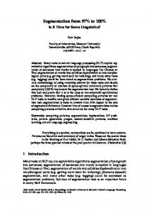
When examining di�erent OO implementations of graphics systems and libraries we nd that objects and abstract classes are used mainly for modelling part. Such system usually provides abstract solids, materials and lights, from which the specialized classes are derived and instantiated to objects forming the scene. Objects generate drawing primitives using some kind of RenderSelf method. Rendered points are stored directly to frame&depth bu�er, multipixel primitives pass through the standard 3D graphics pipeline. Pipeline solves smooth interpolated rendering of simple drawing primitives, whose geometry and color can be processed e�ciently with fast interpolators. The idea originates in seventies and the resulting architecture is thus partitioned to serialy connected function blocks. Data stores attached to processes (functional blocks) save optional parameters for relevant functional transformation. This arrangement obviously cannot solve global illumination as the every single step in pipeline uses only local relations between primitives and lights. Simpli ed result of analysis reveals typical arrangement of functional block depicted as data ow diagram ([Your89]) in Figure 1a. Naive conversion from DFD to OO yields pseudo object with triad of methods SetState, GetState, Transform and weakly 1 encapsulated attributes Figure 1b.
Figure 1: a) Processes and data store b) "Pseudo object" in pipelined processing Transforming traditional program structures to objects this way is straightforward, but it violates rules and recomendations that make OO technology 1 SetState,
GetState
methods serve for direct access to the parameters.
2
powerfull. Such conversion preserves original function oriented structure and it brings nothing new. The importance of OO architectures has been recognized long time ago. The growing number of OO aplications and the vision of reused SW objects to be sold on demand from catalog calls for the uni ed architecture concept applied at all system levels. This work wants to emphasize the above mentioned discrepancies and to reveal uniform view of OO HW and SW architectures.
2 Previous work Graphical entities may be often found in OO literature as examples of multilayered class hierarchies. These hierarchies tend to organize graphical objects to the classes that share either the same type of model (implicit surfaces, parametric surfaces, B-rep primitives) or the same type of access methods (constructors, manipulators) or both ([Egbe92],[Slus96]). Several authors designed object-based renders suitable for implementation of broad classes of geometry and lighting methods. As an example see [Fell95, Fell96], that describes Minimum Rendering Tool {MRT. Architecture uses part-of hierarchy Scene-Object-Surface where Surface is a base class for all illumination models. Object Image is an agent using Camera that controls the main loop over all pixels. It communicates with IllumScene containing several Light s. Other approaches exploit some kind of physically based rendering architecture. Slusallek and Seidel [Slus95] use abstract class GeoObject specialized to Surface and Volume classes, LightSourceShader, Shader, VolumeLighting and Lighting. The resulting Vision architecture replaces explicit knowledge neccesary for global illumination with local propagation methods that use only direct communication between the entities. Classes View, Camera and Film take care of image description that is strictly separated from scene description. The work presented in this paper was inspired primarily by SW architecture described in [Chen95]. We will shortly review the features of architecture in the next section.
3
3 Testbed for Global Illumination Any rendering system contains three fundamental parts: geometry, display architecture and shading methods. This the starting point of the "Testbed for global illumination" described in [Chen95]. For the short review of this architecture, following examples and derived architectures we employ notation of FUSION method [Cole94] - object models (OM) and object interaction graphs (OIG). Display architecture exploits camera based projection methods and hidden surface ellimination in image space. Shading methods are closely related to surface properties and can have both local and global scope. A basic object of testbed is Scene. It encapsulates 3D and 2D world objects organized in part-of hierarchy: Frame, Camera, collection of RenderableObject s and collection of Light s. Each RenderableObject contains instances of two objects: Geometry and Shader. Geometry describes the shape of geometrical entities the system is able to render. Shader takes over the most of functionality that resided originaly in render. It is bidirectional in the sence that shader not only can evaluate intensity at a surface point but also can deposit energy. The communication between Shader and Geometry is accomplished through dynamic object Neighborhood, an abstraction of the di�erential geometry at a point on the surface of geometrical entity. The Scene also de nes display architecture, i.e. local or global illumination algorithms, viewing and lightning. The authors applied uni ed approach to renderables and lights - any Light contains instance of RenderableObject and so it has Geometry that de nes the shape of light and can be rendered with Shader. The class Light has virtual method GiveIntensity, that returns the intensity of light at given point in space. The part-of arrangement of classes is show in Figure 2. Scene is specialised according di�erent illumination methods. Virtual method Render explores all renderables and projects visible surface points to the plane of frame. For every visible RenderableObject it calls its "partof" object Shader and using either Collect or Deposit it takes or hands over light energy. This is the core of experimental architecture that enables to implement various rendering methods. Some examples are described in following sections. To show the behaviour of rendering architectures we use object interaction graphs. OIG illustrates the cooperation among individual objects and collections of objects. Hier4
Figure 2: Object model - part{of class hierarchy archical message numbering demonstrates sequential and possible parrallel message passing.
3.1 Example I - Scene with local lighting
OIG in Figure 3 shows simple solution of specialised object RTScene that is designed to render a scene with local illumination of visible objects. Visibility and lighting are calculated for primary rays. Method Render rst initiates the states of relevant objects (frame, camera). (1)WhatCamera is used to set the viewing transformation and ideal picture quality with respect to optics parameters of "real" camera. RTScene implements standard ray-casting algorithm. It adresses the collection of renderable objects with messages (2)Intersect. When the intersections exist RTScene receives the "names" of new Neighborhood objects representing intersection points and it selects the appropriate surface point i.e. the closest one. (3)Collect message activates internal Shader of selected object. The Shader calculates local lighting model for the neighborhood with precalculated attributes - message (3.1)Inspect. It may use "standard" shadow rays (3.2, 3.3) that nd all visible lights and their contribution to neighborhood intensity. Finally the overall intensity is stored to frame bu�er with (4)Modify message.
5
Figure 3: OIG for local illumination - ray casting method
3.2 Example II - Ray tracing with secondary rays
RTScene can be easily adapted for recursive ray tracing method. OIG in Figure 4 shows the principle: Object Shader activated with message (3)Collect casts secondary rays with respect to BRDF and Neigborhood of RenderableObject. The collection of secondary rays forms the (unorganized) queue and recursion is thus replaced with iteration. RTScene takes over secondary rays with (3.3)InspectRay and ray tracing continues with the subsequent messages (3)Collect. Every step of ray traycing adds some light energy to original pixel or subpixel with (4)Modify(ImagePart). Secondary rays have no special intelligency, they only store the state of running computation. This version enables to control computation in several ways: to limit the number and depth of secondary rays, to test the rays importance and to use various adaptive antialiasing methods. The lights included in collection of renderables are processed in the same way as other objects and they pass their light energy also with Collect message.
6
Figure 4: OIG - ray tracing with secondary rays
3.3 Example III - Ray tracing with Ray objects
Di�erent solution uses dynamically created Ray objects. As shown in Figure 5 RTScene responds to message Render by casting primary rays. Every object in Ray collection addresses renderable objects with (3)Intersect message and it is responsible to select the appropriate intersection and neighborhood. Shader s of renderable objects also cast the new Ray s. Criteria terminating computation are distributed both in rays and shaders and can be applied locally. Ray is responsible to collect light intensity and to (5)Modify pixels in frame. Compared with example II in previous section here Ray objects have more sophisticated logic. They can be also specialised and use some ray-coherent approaches, e.g. beam tracing.
3.4 Example IV - Radiosity
The Shader method (3)Deposit supports the computation of global illumination model with radiosity. It allows the object to store incoming energy to Neighborhood and in accordance with the optical properties to emit the part of this energy. Various combinations are possible but the architecture o�ers cheap and easy solution especially for progressive radiosity. OIG for the Scene with radiosity is in Figure 6. Con guration factors are computed using projection to frame&depth bu�er. 7
Figure 5: Ray tracing with Ray objects Intermediate results are stored into a renderable object e.g. in the form of a radiosity map. Progressive radiosity is computed as following: Repeat Find RenderableObject with the greatest deposited energy. For all other objects: Place camera to surface, that will receive the energy. Project all objects with camera to ReceivingObject , store projection in Frame . // Frame&depth buffer is used for HSE// Visible part of emitter determines config.factor. Store the portion of energy with Deposit in receiving object. until (valid terminating condition).
Deposited energy may be used in further processing, e.g. when ray traycing.
3.5 Objects in 3D scene with sorting
Useful abstraction for 3D sorting used in graphical applications is explorermap analogy. More or less intelligent object Explorer is to ful ll commands 8
Figure 6: Progressive radiosity - basic arrangement (virtual methods) GoOn and GoBack. The method GoOn serves for walking around the 3D scene in such a way that activating site (some controller or agent) would get progressively all neccessary information (e.g. the names of visible objects). In a trivial case (no map or when a new map of yet unexplored area is completely blank) Explorer sends messages to all registered objects one by one without any sorting. The method GoBack returns Explorer to some prede ned or remembered starting point. Sophisticated sorting methods based on computational geometry results provide the sorting structures, which signi cantly reduce the number of tested and reported objects. These methods are based either on global space subdivision done in preprocessing phase, or on dynamicaly maintained local sorting structures. Object Explorer is designed at high abstraction level and it serves as prototype - base class, that can be further specialized, i.e. trained for more sophisticated behaviour. Scenario for sorted scene with explorer is shown in Figure 7. The dashed line in Figure 7 shows the traditional border that separates HW and SW part of rendering system. 9
Figure 7: OIG - Architecture of scene with sorting
4 Architecture Cohen&Demetrescu The foregoing examples indicate the interesting possibilites of OO SW architectures. It is clear that such architectures o�er many possibilities for experiments with rendering methods and that they can be used as a tool to explore new and optimal OO architectures. In the next section we will try to setup the analogous model for (parallel) HW architecture. As essencial architecture we selected the generalised Cohen&Demetrescu architecture. Architecture Cohen&Demetrescu belongs to the class of parallel architectures of procesor/object type. The description and features may be found in [Deme80]. Figure 8 shows this architecture in general form that allows MIMD parallelism. Every processor gets object data and computes its contribution to scene image. Data stream passing through serialy connected processors is used to compose nal image. The original design described one-pass generation of complete image, but we allow the more exible feedback loop closed via frame bu�er. Compositing architecture can work in many di�erent ways. The examples of possible HW/SW architectures are listed below: •
Processors are specialized for certain object classes. Serially passing data, pixels with color and depth are modi ed by individual processors. 10
Figure 8: Generalized architecture Cohen&Demetrescu
•
•
One-pass antialising can be also applied. The rst processor expands incoming pixel data to the group of subpixels. This subpixel collection is processed step by step in chained processors that may be optimized for di�erent types of primitives. Last processor computes convolution ltering and antialiased pixel data are stored in frame bu�er. Processors use intermediate frame bu�ers to store some part of image. Special composition blocks synchronously assemble nal image and store it to frame bu�er. Composition blocks solve visibility (using pixel depth) and transparency (e.g. α-blending). Architecture distributes input primitives to slected processors according their specialisation and workload (Figure 9).
Figure 9: Composition architecture 11
•
Drawing primitives are de ned as halfspaces F (x, y, z ) ≤ 0 [Fuch85, Fuch89]. Special pixel processors evaluate in constant time multipixel regions covered by primitives. Result is again composed serialy [Moln92].
Object interaction in generalized Cohen&Demetrescu architecture is depicted in Figure 10. It is similar to architecture in Figure 7, object ExplorerwithMap is not shown here.
Figure 10: OIG - Rendering in generalized Cohen&Demetrescu architecture
5 SW and HW OO architecture overlay We attempt to nd convenient architecture, that would combine both the principles of object oriented system design for realistic rendering and the principles of parallel solution of graphic tasks in specialized architectures. To demonstrate unifying approach with an example we chose architecture with dynamic objects of class Ray, that uses the similar work breakdown structure as the architecture RTScene (Figure 5). When we combine explorer/map architecture with raytracing architecture, we get the structure 12
with behaviour scetched in Figure 11. Object Scene is replaced by object Painter, RenderableObject s contain Geometry and Shader as before. Shader remains the part of renderable object, but it is accesable for UniversalShader with the method (6)GetShader. Shading is derived from environment of point in 3D space and renderable objects may undergo more shading methods.
Figure 11: OO architecture - scene with realistic rendering Architecture o�ers at least two apparent places suitable for parallel solution with a special HW architecture. Objects of type Ray and Geometry form the (unorganized) queue of planned geometric tasks that are to nd intersection of some ray with the nearest surface ((3)Intersect ). Here it is possible to employ generalized Cohen&Demetrescu architecture composed of ray processors and geometry processors. Object ExplorerwithMap that is responsible for space sorting and searching (maintaining and using map) activates relevant, but not neccessary visible renderable objects. Activated objects choose (are placed into) suitable geometry processor and provide part of their geometry in GeomDescription data. Temporary PartialGeometry objects are mapped to geometry processors that solve ray-geometry intersections. During serial processing the geometry processors compute and select the nearest intersection with di�erencial neigborhoods. The result is stored as ValidNeighborhood. This new object 13
stores also the description of original ray. ValidNeighborhood objects form the second processing stream for specialized shading architecture. UniversalShader takes over ValidNeighborhood with (5)Inspect message, then asks for object shader ((6)GetShader ) and activates one or more shader processors. Architecture may contain either several identical shaders or a combination of special shaders e.g. for procedural or mapped textures. Shaders store calculated pixel or region information to frame bu�er, but they also generate new secondary rays with (7)CastRay. Assuming that ray besides geometry information contains also the data used for light energy integration this architecture supports various global illumination techniques. Reorganized architecture that uni es OO description of all partial rendering methods is in Figure 12.
Figure 12: OO architecture projected on parallel architecture Model in Figure 12 shows one particular solution - OO design of RT architecture. As we want in the future to follow the same philosofy for more 14
complex architectures we generalize the previous architecture to the form shown in Figure 13.
Figure 13: Conceptual architecture for realistic rendering The properties of the derived architecture are brie y listed below: 1. Architecture consist of 3 main parts: ExplorerWithMap, GeometryArchitecture, ShadingArchitecture. All parts are independent subsystems with de ned responsibilities, interface and behaviour. Objects can be exchanged or modi ed easily because they are loosely coupled. 2. The behaviour of each object and of complete architecture can be described with short speci cation. 3. All active objects can exploit parallel solution realized with general or a special architecture. 4. Dynamic objects ValidNeighborhood facilitate asynchronous communication amid geometry tasks (intersections etc.) and integration tasks (computation and composition of light contributions at surface and/or image points). 5. Objects can be used in di�erent assemblage not only for derivates of classical rendering methods but also for the systems with haptic feedback.
6 Conclusion and Further Work We have presented an experimental OO architecture for the scenes with global illumination. Design de nes the fundamental classes that form the 15
base for detailed decomposition and can be easily augmented. Our goal is to develop uniform architecture both for visualisation and haptics, i.e use di�erential environments for force feedback computation.
References [Chen95]
Chen S.E., Turkowski K., Turner D.: An Object{Oriented Testbed for Global Illumination. In: La�ra et al. (Eds.) Object{ Oriented Programming for Graphics. Springer{Verlag, 1995, pp.155{166 [Cole94] Coleman,D. et al.: Object{Oriented Development. The FUSION Method. Prentice{Hall,Inc., 1994 [Deme80] Demetrescu,S.: A VLSI Based Real Time Hidden Surface Elimination Display System. Master's Thesis, Department of Computer Science, CALTECH, Pasadena, CA, May 1980 [Egbe92] Egbert,P.K., Kubitz,W.J.: Application Graphics Modeling Support Through Object Orientation. In: COMPUTER, October 1992, pp.84-91 [Fell95] Fellner,D.W.: MRT - An Extensible Platform for 3D Image Synthesis. Computer Graphics Lab., Dept. of Computer Science, University of Bonn, Germany, Dec. 1995 [Fell96] Fellner,D.W.: Extensible Image Synthesis. In: Object-Oriented and Mixed Programming Paradigms, Wisskirchen P., (Ed.), Focus on Computer Graphics, Springer, Feb. 1996 [Fuch85] Fuchs,H. et al.: Fast spheres, shadows, textures, transparencies, and image enhancements in Pixel-Planes. Computer Graphics,19,3,July 1985. [Fuch89] Fuchs, H. et al.: Pixel-planes 5: A heterogeneous multiprocessor graphics system using processor-enhanced memories. Computer Graphics 23,3 (July), pp.79-88 16
[Gold86] [Kede84] [Kris94] [Moln92] [Port84] [Poul92] [Riel96] [Schn91] [Slus96]
[Slus95] [Your89]
Goldfeather,J.-Fuchs,H.: Quadratic surface rendering on a logic-enhanced frame-bu�er memory. Computer Graphics&Aplications,1,January 1986. Kedem,G.-Ellis,J.: Computer structures for curve-solid classi cation in geometric modelling. Technical report TR137, Department of Computer Science, University of Rochester, May 1984. Kristen,G.: Object{Orientation. The KISS Method. Addison{ Wesley, 1994 Molnar,S.,1992: Pixel ow: High-speed rendering using image composition. Computer Graphics 26, 2 (July), pp.231-240 Porter,T.,Du�,T.: Compositing Digital Images. Computer Graphics, 187(3): 253{259, July 1984. Poulton,J.,Eyles,J.,Molnar,S.,Fuchs,H.: Breaking the FrameBu�er Bottleneck with Logic-Enhanced Memories. IEEE Computer Graphics&Applications, November 1992 Riel, A.J.: Object{Oriented Design Heuristics. Addison{Wesley, 1996 Schneider,B.: Towards a Taxonomy for Display Processors. In: Strasser W.,Grimsdale R.L.(Eds.) Advances in Computer Graphics Hardware IV., Springer{Verlag, 1991 Slusallek,P.,Klein,R.,Kolb,A.,Greiner,G.: An Object Oriented Approach to Curves and Surfaces. In: Wisskirchen,P.(Ed.) Object-Oriented and Mixed Programming Paradigms, Springer Verlag, 1996 Slussalek,P., Seidel,H.P.: Vision - An Architecture for Global Illumination Calculations. In: IEEE Trans. Visualization & Computer Graphics 1(1), 1995 Yourdon,E.: Modern Structured Analysis Yourdon Press, Prentice{Hall, New York 1989. 17
c 1998, Faculty of Informatics, Masaryk University. Copyright All rights reserved. Reproduction of all or part of this work is permitted for educational or research use on condition that this copyright notice is included in any copy.
Publications in the FI MU Report Series are in general accessible via WWW and anonymous FTP: http://www.fi.muni.cz/informatics/reports/ ftp ftp.fi.muni.cz (cd pub/reports) Copies may be also obtained by contacting: Faculty of Informatics Masaryk University Botanická 68a 602 00 Brno Czech Republic