tive, light water reactor with a modular, integral pri- mary system configuration. The reactor pressure ves- sel houses the nuclear fuel, control rods and con-.
Proceedings of the 4th International Modelica Conference, Hamburg, March 7-8, 2005, Gerhard Schmitz (editor)
A. Cammi, F. Casella, M. Ricotti, F. Schiavo Politecnico di Milano, Italy Object-Oriented Modeling, Simulation and Control of the IRIS Nuclear Power Plant with Modelica pp. 423-432
Paper presented at the 4th International Modelica Conference, March 7-8, 2005, Hamburg University of Technology, Hamburg-Harburg, Germany, organized by The Modelica Association and the Department of Thermodynamics, Hamburg University of Technology All papers of this conference can be downloaded from http://www.Modelica.org/events/Conference2005/ Program Committee • Prof. Gerhard Schmitz, Hamburg University of Technology, Germany (Program chair). • Prof. Bernhard Bachmann, University of Applied Sciences Bielefeld, Germany. • Dr. Francesco Casella, Politecnico di Milano, Italy. • Dr. Hilding Elmqvist, Dynasim AB, Sweden. • Prof. Peter Fritzson, University of Linkping, Sweden • Prof. Martin Otter, DLR, Germany • Dr. Michael Tiller, Ford Motor Company, USA • Dr. Hubertus Tummescheit, Scynamics HB, Sweden Local Organization: Gerhard Schmitz, Katrin Pr¨olß, Wilson Casas, Henning Knigge, Jens Vasel, Stefan Wischhusen, TuTech Innovation GmbH
Object-Oriented Modeling, Simulation and Control of the IRIS Nuclear Power Plant with Modelica
Object-Oriented Modeling, Simulation and Control of the IRIS Nuclear Power Plant with Modelica Antonio Cammi∗, Francesco Casella†, Marco E. Ricotti∗, Francesco Schiavo†‡ Politecnico di Milano, Piazza Leonardo da Vinci 32 20133 Milano Italy
Abstract The paper presents the application of the Modelica language to the modeling, simulation, and control of the new IRIS nuclear power plant, under development by an international consortium. The plant model, developed by using components from the ThermoPower library, as well as custom-built nuclear components, is described, as well as the digital control system model, which will eventually become very realistic. Special emphasis is put on the use of inheritance and replaceable objects for the management of a family of model variants over the project life-time. Selected simulation results are included.
1
Introduction
The IRIS project [3] involves 21 organizations from 10 countries and refers to the design of an innovative, light water reactor with a modular, integral primary system configuration. The reactor pressure vesFigure 1: The IRIS Reactor sel houses the nuclear fuel, control rods and control rods drive mechanisms, but also all the major reactor coolant system components, including the Compared to conventional PWR plants, however, IRIS coolant pumps, the steam generators and the pressur- has a set of distinctive features, which directly affect the control system design: izer (Fig.1). • the integral configuration requires a large water IRIS is basically a PWR (Pressurised Water Reactor): inventory in the primary loop, whose residence in the primary loop, liquid water is heated by the nutime is much greater than usual; clear fuel rods in the core, and is then sent by the pumps to the primary side of heat exchanger; the sec• a helicoidal once-through steam generator is emondary loop actually generates steam which is sent to ployed on the secondary side, which has a very turbines to produce power. short residence time, compared to the more widespread U-tube recirculating steam genera∗ Dipartimento di Ingegneria Nucleare “E. Fermi”CESNEF, tors; {antonio.cammi,marco.ricotti}@polimi.it † Dipartimento di Elettronica e {casella,schiavo}@elet.polimi.it ‡ Corresponding author
The Modelica Association
Informazione,
423
• sprayers are not available to reduce the pressure in the primary loop during fast transients. Modelica 2005, March 7-8, 2005
A. Cammi, F. Casella, M. Ricotti, F. Schiavo
The control strategy must take these facts into account, and a dynamic simulation tool is essential to ensure that the control objectives can be achieved. Highly detailed dynamic simulators have been developed for the IRIS reactor [6]. Such simulators, based on the complex computational fluid-dynamics code named RELAP [10], are perfectly suited for accident analysis and safety-oriented evaluations of the reactor design features. On the other side, due to the amount of the details involved, they cannot be proficiently used for control-oriented dynamic simulation. Within this framework, the use of the Modelica language offers a viable solution, allowing the development of dynamic simulators that are detailed enough for control-oriented analysis and yet with limited computational requirements. To provide the required capabilities for the analysis, specific models for nuclear reactor components have been developed, to be applied for the dynamic simulation of the IRIS integral reactor, albeit keeping general validity for PWR plants. In addition to that, specific digital control blocks have been developed, so that a complete model of the plant and of its digital control system is available. The paper is organized as follows. An overview of the plant model is presented in Section 2, while in Section 3 the models specifically developed for nuclear components are analyzed in detail. Section 4 contains an overview of the plant digital control system and, in Section 5, the problem of managing a library of plant models with different detail levels is tackled. Section 6 presents some closed-loop simulation results. Finally, Section 7 draws some conclusions and outlines possible future developments.
2
Plant Model
The model of the IRIS plant basically describes the primary circulation loop, i.e. the reactor coolant loop, and the secondary loop, i.e. the once-through evaporators, along with the feedwater and turbine systems. Most of the required models have no specific nuclear features, and were thus borrowed from the generalpurpose ThermoPower library, designed for the modelling of generic thermo-hydraulic power plants; the library is an open-source project, described with more detail in [4]. The only notable exceptions are the reactor core and the pressurizer, which are described in the next section. The Modelica Association
Figure 2: Plant flow diagram
2.1
Primary loop
The primary loop (see Fig. 2) starts with the pressurizer (top of the diagram); the pressurizer is connected by a pressure-loss component to the upper mixing volume, taking into account the mass and energy balances. Starting from the top of the diagram, counterclockwise, the centrifugal pump model can be found, followed by another plenum model. The primary side of the heat exchanger between the primary and secondary loop is then encountered, modelled by three cascaded, finite-volume pipe models; the middle one describes the section where the coolant is actually in contact with the secondary side tube bundle. Proceeding onwards, other two plenum models followed by a pressure loss can be found, leading to the inlet of the core model (see next Section). This in turn is followed by another pressure loss, another plenum, and the two riser sections, modelled by two pipes having different diameter. The loop is closed by a simple model of the chemical and volume control system (CVCS), basically a mixer and an ideal flow source. The fluid in the whole loop is one-phase water, with the exception of the steam filling the upper pressurizer dome. The heat transfer between the primary and secondary loop is modelled by two heat transfer modules and by the thermal model of the tube metal mass. The primary-side heat transfer coefficient is held constant to its nominal value, since the Reynolds and Prandtl numbers does not vary substantially; on the secondary side, the heat transfer coefficients can be computed ac-
424
Modelica 2005, March 7-8, 2005
Object-Oriented Modeling, Simulation and Control of the IRIS Nuclear Power Plant with Modelica
cording to different laws, e.g. Chen’s correlation, or much simpler, empirically tuned curves.
2.2 Secondary loop The secondary loop is composed of the feedwater system, the helical coil once-through steam generator and the turbine system. The once-through generator is represented by a finite-volume, 10-node model of the twophase fluid flow, assuming homogeneous flow, i.e. the same velocity for the liquid and vapor phases. Currently, the feedwater system is represented by an ideal flow source, whose flow rate is determined by the control system, and whose enthalpy is a function of the plant load level, determined from balance-of-plant calculations. The turbine system includes a simplified, linear model of the high- and low-pressure turbines, plus simplified models of the connection to the grid, including an idealized synchronous generator, local loads, and a grid model. The latter ones are included to provide suitable boundary conditions for the (much slower) plant dynamics; therefore, they only model active power flows, neglect the electro-mechanical dynamics, and assume perfect synchronism between the generator and/or the grid. In the near future, it is planned to replace the feedwater and turbine system models with more realistic counterparts, including steam bleedings and condensate train, to better represent the actual steam generator dynamics under large load variations. On the other hand, the finite-volume fluid evaporator model could be replaced by a simpler version, with moving boundaries between the liquid, 2-phase, and vapor sections, and an averaged description of each section.
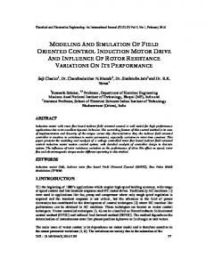
3 Nuclear Components The Modelica models for “nuclear” components have been developed to provide solutions which are suitable both for “general” use and specifically for the IRIS nuclear plant modelling. The main components are the core, (with separate models for the point kinetic neutronic generation, the fuel thermal dynamics and the moderator, as depicted in Fig. 3) and the pressurizer; the main modelling principles are summarized here, for more details see [1, 2].
3.1
Figure 3: The Core Model Internal Structure dynamic balance equations, describing the evolution of the neutronic population and of the precursor concentration. Reactivity feedback from coolant density, fuel Doppler effect, and rod insertion are accounted for. The dynamic terms can be switched off, to obtain a simplified static model, neglecting the fast dynamics. The neutronic power generated into the fuel is proportional to the neutronic population n, which responds to the point reactor kinetics balance equations : 6 dn ρ − β = n + ∑ λi c i dt Λ i=1
dci β = n − λi c i dt Λ
(1)
i = 1, · · · , 6 ,
where c is the precursor concentration leading to a delayed neutron source, ρ is the total reactivity of the core, β is the fraction of delayed neutrons, λ is the decay constant of the precursors and Λ is the characteristic period of the reactor or mean neutron generation time. Reactivity feedbacks are taken into account as well, by considering linear or non linear feedback coefficients, always negative, for the coolant density effect (αc ), the fuel Doppler effect (α f ), the effect of the boron concentration (αB ) into the primary fluid as a neutronic poison and the level of insertion of the control rod banks into the core (αCR ). These relations are
Point Kinetics Neutronic
ρ = ρCR + ρ f + ρc + ρB , � ρ f = α f Te f f − Te f f 0 , ! 1 1 ρc = αc − , vc vc0
(2)
ρB = αB (C −C0 ) ,
The point kinetic neutronic model describes the dynamics of the neutron generation processes in the where Te f f and Te f f 0 are the instantaneous and refercore. The model is based on standard point kinetic ence effective fuel temperature, respectively, obtained The Modelica Association
425
Modelica 2005, March 7-8, 2005
A. Cammi, F. Casella, M. Ricotti, F. Schiavo
from the fuel model, vc and vc0 are the instantaneous equations read: and reference specific volumes of the coolant, C and ! ∂T ∂T ∂ 1 000 p p C0 are the instantaneous and reference boric acid conrk p +q , ρ p c p,p = ∂t r ∂r ∂r centration in the coolant. The boric acid concentration ! in the coolant depends mainly on the control rods in∂ ∂Tg sertion. kg =0 , ∂r ∂r The reference values are those corresponding to the ! ∂Tc ∂Tc 1 ∂ nominal, full power operation of the reactor. = rkc . ρc c p,c ∂t r ∂r ∂r
3.2
Fuel model
The fuel model describes the dynamics of the thermal power generated within the core by the nuclear chain reactions. The neutronic generation model and the fuel model are linked by a connection between two Modelica standard HeatPort, where the connectors variable are the total power generated and the fuel temperature. A ThermoPower DHT distributed heat transfer connector is used as well, as an interface with the moderator, modelled by a 1-D flow model. The model is based on the application of the time dependent Fourier equation (in monodimensional cylindrical geometry) to the three fuel zones: pellet, gap and cladding (Fig. 4).
(3)
where ρ is the density, c p is the specific heat, T is the temperature, k is the thermal conductivity, q000 is the volumetric source term, r is the radial dimension and t the time, while the subscripts p, g and c stand for the pellet, the gap, and the cladding, respectively. The heat transfer model is represented in Fig. 4, with the pellet discretized into three zones of equal volume. Eqs.(3), together with the conditions of heat flux vanishing at the pellet center and the continuity of the temperatures and heat fluxes at the three boundaries pellet-gap-cladding-coolant allow the determination of Tp (r,t), Tg (r,t) and Tc (r,t). In addition to the above equations, five correlations synthesizing the dependance of c p,p , k p , c p,c and kc as a function of the fuel temperature and of kg as a function of both the reactor power and the burn-up have been adopted. The condition at the cladding-coolant interface is determined by the distributed heat transfer connector variables. Finally, the effective fuel temperature, used to evaluate the Doppler feedback contribution on neutronics, is defined as follows: 4 5 Te f f = T |r=0 + T |r=R . 9 9
3.3
(4)
Moderator
The core moderator is modelled by the ThermoPower library Water.Flow1D, with a small extension to make the fluid density available to the point kinetics model. The coolant model has the same number of Figure 4: Fuel pellet radial scheme for heat transfer mod- volumes as the fuel. The convective heat transfer beelling tween the two components is calculated at each node by The main assumption of the model is to consider only φmod = −φc , (5) the radial heat transfer, thus disregarding both the axφmod = γ (Tc − Tmod ) , ial and the circumferential diffusions. Fourier’s equation is discretized radially in five zones, and longitudi- where φmod and φc are, respectively, the moderator and nally in a user-decidable number of segments (N). For the fuel cladding heat flux, γ is the heat transfer cothe pellet, gap and cladding the corresponding balance efficient, and Tmod and Tc are the moderator and fuel The Modelica Association
426
Modelica 2005, March 7-8, 2005
Object-Oriented Modeling, Simulation and Control of the IRIS Nuclear Power Plant with Modelica
cladding temperatures. Detailed RELAP simulations have shown that the heat transfer coefficient is approximately constant for all the operating conditions the control system is concerned with.
3.4
Pressurizer Model
The pressurizer model is based on a lumped parameter approach, which is appropriate to the IRIS case. Both water properties in the liquid volume and in the steam volumes are assumed as homogeneous, at equal pressure but not at thermodynamic equilibrium. The model is based on two groups of dynamic mass and energy balance equations, the first for the liquid phase and the second for the vapor phase inside the tank. Mass and energy transfer between the two phases is provided by bulk condensation and surface condensation of the vapor phase, and by bulk boiling of the liquid phase. Additional energy transfer can take place at the surface if the steam is superheated. External interfaces are provided for connections to the hydraulic loop by a bottom flange and to a safety circuit by a safety flange; also available are a heating power command input and a level signal probe output. The heating power input is processed by a limiter and a low pass filter block to simulate the delay in heating effect and the limited heaters power. The resulting effective heating power signal drives the production of saturated steam by the heaters at a rate corresponding to the difference between the enthalpy of the liquid holdup and the enthalpy of saturated steam. For simplicity, the corresponding steam flow enters directly the steam holdup, without causing heating of the liquid holdup. The bottom flange’s flow enters directly the liquid volume; its pressure is increased depending on the liquid holdup’s level. The metal wall dynamics is taken into account, assuming uniform temperature. Heat transfer takes place between the metal wall and the two phases and between the wall and the external ambient at fixed temperature.
4
Control
Figure 5: Control system architecture At the top level is located a supervisory control system with the following functions: • Establish the plant electric power reference signal. Such reference signal will be used to derive reference and/or feedforward signals for the other major control loops. • Monitor plant conditions and determine/coordinate the appropriate operating modes for the major control systems. The control sub-systems have different settings and a varying structure (i.e., different inputs and different controller structure) depending on the specific operating mode of the plant. All the operating modes to drive the plant during the non-emergency maneuvers have been designed [8]; nevertheless, only the “full-power” control mode (nuclear flux from 20% to 100%) has been fully implemented, simulated and tested yet, so, from here on, the description will cover only such operating mode.
4.1
The control design of the IRIS nuclear power plant is a complex task, with objectives that, depending on the plant operating conditions, vary from the management of start-up sequences to the recover from turbine or reactor trips and to the grid power/frequency regulation at full nuclear power. The Modelica Association
Classic design concepts, for early nuclear units, relied on separate control systems for each control loop, and limited signal interaction between the loops [9]. This simplified the design of each loop, particularly with analog control systems where each interconnection added hardware expense. On the other side, the current trend is for more integrated systems that can take advantage of coordinating the different control loops [7]. This allows for more effective plant control, but complicates the control system failure analysis. A viable solution for IRIS is the choice of a hierarchical control system, as depicted in Fig. 5.
Supervisory Control
The supervisory control system uses the normalized desired power as an input signal to derive the reference and feedforward signals for the lower-level control systems. On the base of the desired power the temperature and nuclear flux reference for the reactor control are derived, along with a pressure reference for the
427
Modelica 2005, March 7-8, 2005
A. Cammi, F. Casella, M. Ricotti, F. Schiavo
The control is based on a PID, its input being the reference pressure signal coming from the supervisory control system and the actual steam pressure measured at the turbine inlet, with suitably low-pass filtering action. The PID output is then summed to the amplified frequency mismatch (i.e., the difference between the actual generator frequency and the desired frequency), with the gain depending on the grid droop setting. The 4.2 Reactor Control resulting signal is fed to the TAV drive system after beThe aim of the reactor control is to control the coolant ing filtered by a non-linear algebraic function, which temperature, and thus the reactor nuclear power, by is an approximate inverse of the TAV characteristic. driving the control rods stepping system. As a matter of fact, the reference is a temperature signal coming 4.4 Steam Dump Control from the upper level, while the measurements include the core coolant average temperature (obtained as the The steam dump control system must control steam mean between the temperature at the core inlet and the pressure when the turbine admission valve control is one at the core outlet) and the nuclear neutron flux (ob- not doing so, and must provide a backup in all other tained through special sensors enclosed within the core cases. Experience shows that a simple PID control pershielding). forms well, particularly if the system uses hydraulic The temperature error, with suitable dynamic compen- steam dump valves, as it will be in the IRIS case. sation, is used to generate an error signal for determin- The controlled variable is the steam dump valve opening the speed request for the control rods, along with ing, while the controller inputs are the pressure refera power mismatch signal which is used to improve the ence (from the upper level) and the turbine inlet steam stability and the velocity of the reactor control system pressure (low-pass filtered). Additional steam-dump response. The power mismatch signal (i.e. the dif- action is available in case of need: the power referference between the reference and the measured neu- ence, filtered through a rate compensator and a suittronic flux) is fed into a rate compensation filter, to able gain, is added to the steam dump valve control eliminate steady-state influence, and then into a non- signal, to provide a faster response in case of sudden linear, power-dependant gain, to improve low-power changes in the requested power (e.g., when a reactor or response while avoiding high frequency excitation of a turbine trip occur and the supervisory control system the rod stepping system. instantaneously lowers the power reference). The combined error signal enters a rod speed program that features a small dead band to avoid high frequency rod stepping. The speed request thus gen- 4.5 Feedwater Control erated is then serviced by a servo control system em- The feedwater control system directly controls the bedded within the control rods drive mechanism. This feedwater flow in the secondary side by acting on a servo is currently described by a high-level behav- valve located at the feedwater pumps. The structure is ioral model, which could be eventually replaced by a based on two PID controllers in cascade configuration. physical-based model. The inner loop acts to control feedwater flow to the refturbine and steam dump control systems and with the flow rate reference for the feedwater control. The signals to be fed to the lower systems are derived from the desired power reference with linear filtering and through look-up tables based on steady-state plant balances.
4.3 Turbine Admission Valve Control The turbine system for the IRIS power plant has not been completely designed yet and it is reasonable to assume that the turbine supplier will provide most of the requirements for the turbine control system; however, the design must be compatible with the overall IRIS plant control strategy. The most important constraint is that the IRIS turbine control will have the responsibility for controlling steam pressure by acting on the turbine admission valve (TAV). The Modelica Association
erence value obtained from the supervisory control. In the ideal case with perfect settings in the supervisory controller, this would result in the plant operating at the desired power, at least in steady state. Of course, such an open loop control on power would be sensitive to parameter variations, so the outer loop provides a trim signal to adjust feedwater flow to achieve the desired power by the action of a PID controller with the reference and the actual power as inputs. The feedwater valve control signal is then filtered by a non-linear algebraic function, which is an approximate inverse of the valve characteristic.
428
Modelica 2005, March 7-8, 2005
Object-Oriented Modeling, Simulation and Control of the IRIS Nuclear Power Plant with Modelica
4.6 Digital PI controller
CS = CSmin; CSport.signal[1] = CSmin;
Models for digital PI and PID controllers, in ISA form, else CS = CSwind; have been implemented. Here, for the sake of brevity, CSport.signal[1] = CS; only the PI development is briefly showed: the PID end; model development is quite similar. else The model is based on the standard industrial ISA for... mulation, with the output calculation formula obtained where the parameters CSmax and CSmin, are the upwith a Tustin discretization: per and lower saturation limits for the control action. ! With this implementation structure, the controller inte1 CS(s) =K p (bSP(s) − PV (s)) + (SP(s) − PV (s)) gral state is automatically updated at every execution TI s cycle so to be coherent with the last output sample. ! ⇓
Tustin: s =
CS(z) =SP(z)
2 z−1 Ts z + 1
(6)
5
a0 + a1 z−1 b0 + b1 z−1 + PV (z) 1 − z−1 1 − z−1
Model Management through the project life-cycle
with
Object-oriented features such as inheritance and replaceable components are often described as key factors in the development of reusable model libraries. . In fact, they can also be extremely useful for the proper management of families of application models The complete controller model includes also advanced throughout an engineering project’s lifetime, as it will features like manual and tracking working mode, out- be explained in this section with reference to the IRIS project. put saturation, and anti wind-up mechanism. The resulting block has two boolean inputs (automatic and tracking switch signals), four discrete real inputs 5.1 Requirements (set-point, process value, manual and tracking signals) During the IRIS project lifetime, a considerable numand a discrete real output (control signal). The Modelica implementation exploits the language ber of model variants will have to be built and anafeatures for digital blocks, using discrete variables and lyzed; some of them will become obsolete and will with the instructions enclosed within a sampling loop: have to be discarded, while others should be kept consistently up-to-date. The motivations of the model when {initial(),sampleTrigger} then variants are now briefly discussed. ... [PI computations] Depending on the specific simulation to be performed, ... different accuracy vs. computational load trade-offs end when; are required. Reference simulations should be perThe anti wind-up mechanism is implemented via an formed with the maximum level of accuracy and deauxiliary variable: tail, and cross-checked with the results of the reference simulations performed with the certified RELAP CSwind=pre(CS)+a0*SP+a1*pre(SP)+b0*PV+ code. When performing simulations around a certain b1*pre(PV); operating point, some approximations could then be where Cswind is the auxiliary variable, CS the con- introduced, which are only valid for that operating retrol variable, SP the set-point and PV the process gion; it should be possible to easily check simplified value. versions against their more accurate counterparts. The actual control value is chosen depending on the Some of the plant parameters (e.g. the pump charactercontroller logic state (automatic, manual or tracking) istics, or some plenum volumes) are not yet definitive, and on the saturation values, e.g. : and could change in the future; when one of such paif AUTO then rameters is changed, it is essential that all the current if CSwind >= CSmax then model variants are updated consistently. CS = CSmax; Once the initial phase of the control system design has CSport.signal[1] = CSmax; been carried out, a systematic simulation campaign elseif CSwind